

Page 1
CM 201G
Valid as of G21ME0404 up to
G21ME0601
Gas unit
X CM 201G
Voltage 1 NAC 120V 60Hz
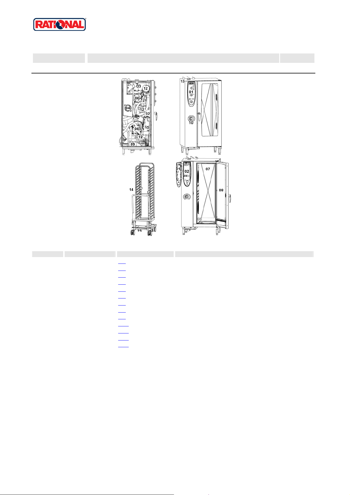
Item no. Part no Reference Description
1 X1 Control panel
2 X2
3 X3 Clima Plus
4 X4
5 X5
6 X6 Motor and fan wheel
7 X7
8 X8 Door
9 X9
10 X10 Hand shower
12 X12
13 X13
14 X14
Electrical installation
Steam generator, Bypass
Hot air heating
Interior cabinet
Water supply, quenching box
Gas parts
Exterior cabinet
Miscellaneous
Version 2006 1
Page 2

CM 201G
Gas unit
X Table of contents
Voltage: 1 NAC 120V 60Hz
1 Control panel ..................................................................................................................3
1.A Control panel..........................................................................................................................................................4
1.A Control panel..........................................................................................................................................................5
2 Electrical installation .......................................................................................................6
2.A Contactor assembly ...............................................................................................................................................7
3 Clima Plus.......................................................................................................................9
4 Steam generator, Bypass .............................................................................................10
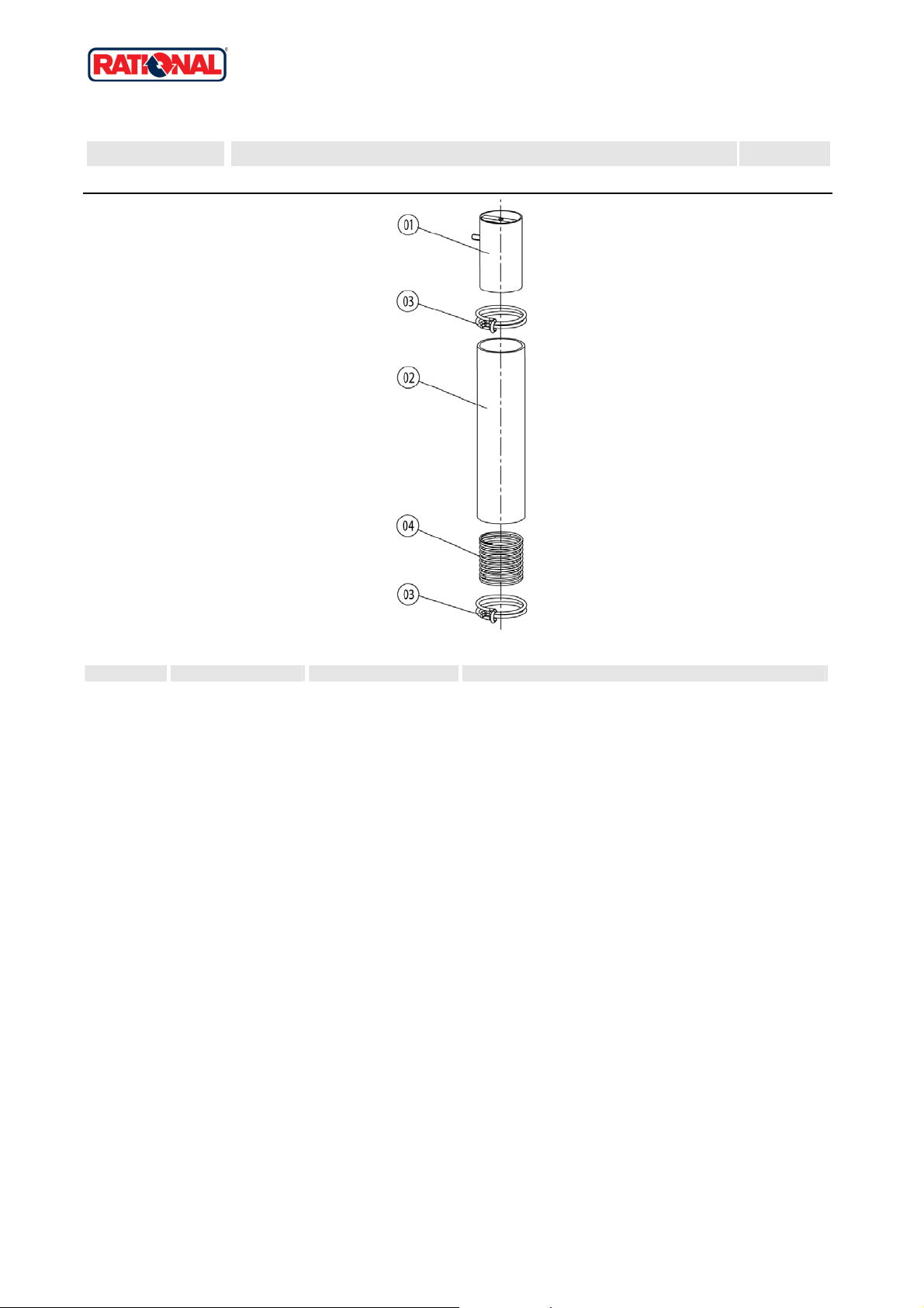
4.A Pump connection spout cpl..................................................................................................................................12
4.B Venting valve for steam generator .......................................................................................................................13
5 Hot air heating ..............................................................................................................14
5.A Burner hot air .......................................................................................................................................................15
6 Motor and fan wheel.....................................................................................................16
7 Interior cabinet..............................................................................................................17
7.A Interior cabinet welded.........................................................................................................................................18
7.B Gasket frame w. glass a. gaskets ........................................................................................................................19
7.C Air baffle...............................................................................................................................................................20
7.C Air baffle...............................................................................................................................................................21
8 Door..............................................................................................................................22
8.A Door .....................................................................................................................................................................24
8.C Door catch............................................................................................................................................................25
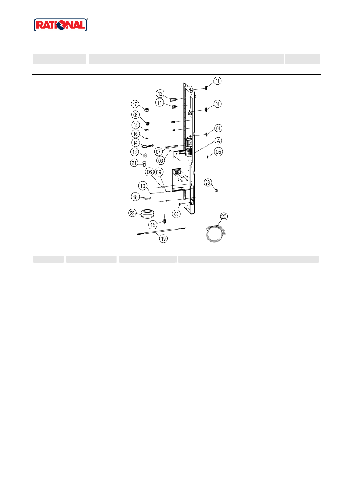
9 Water supply, quenching box........................................................................................26
10 Hand shower...............................................................................................................27
12 Gas parts....................................................................................................................28
12.A Gas valve cpl. ND 055 RG148...........................................................................................................................30
12.B Gas valve cpl. WND 055 RG130........................................................................................................................31
13 Exterior cabinet...........................................................................................................32
13.A Exterior cabinet..................................................................................................................................................33
14 Miscellaneous.............................................................................................................34
2
Page 3
CM 201G
Valid as of G21ME0404 up to
G21ME0601
Gas unit
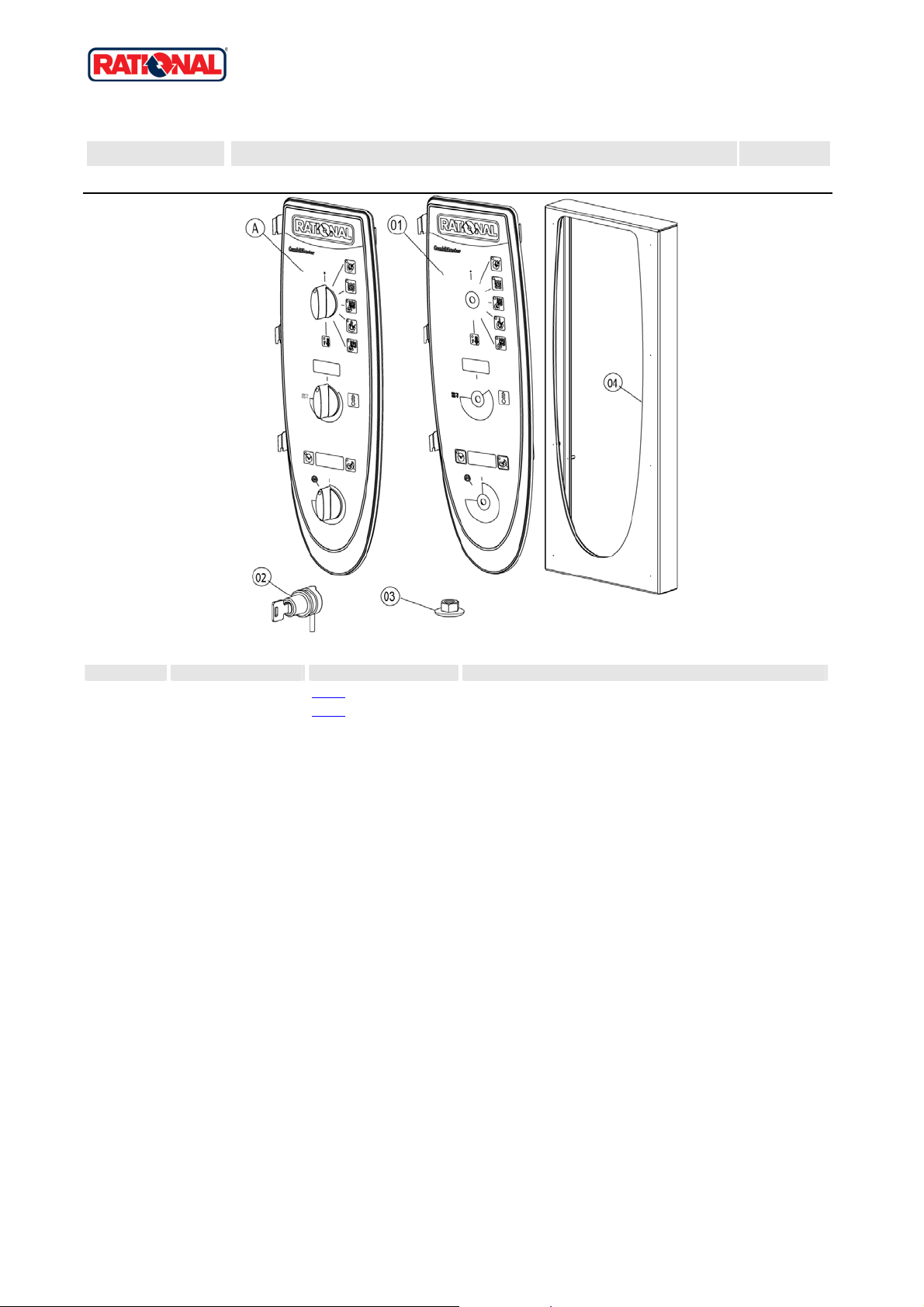
1 Control panel
1 Control panel
X 1 Control panel 1
Voltage 1 NAC 120V 60Hz
Item no. Part no Reference Description
A X1.A Control panel
A X1.A
1 87.00.003 Control panel insert with overla y
Control panel
Attention! Individual parts shown might not be used in this component group!
Version 2006 3
Page 4
CM 201G
Valid as of G21ME0404 up to
G21ME0601
Gas unit
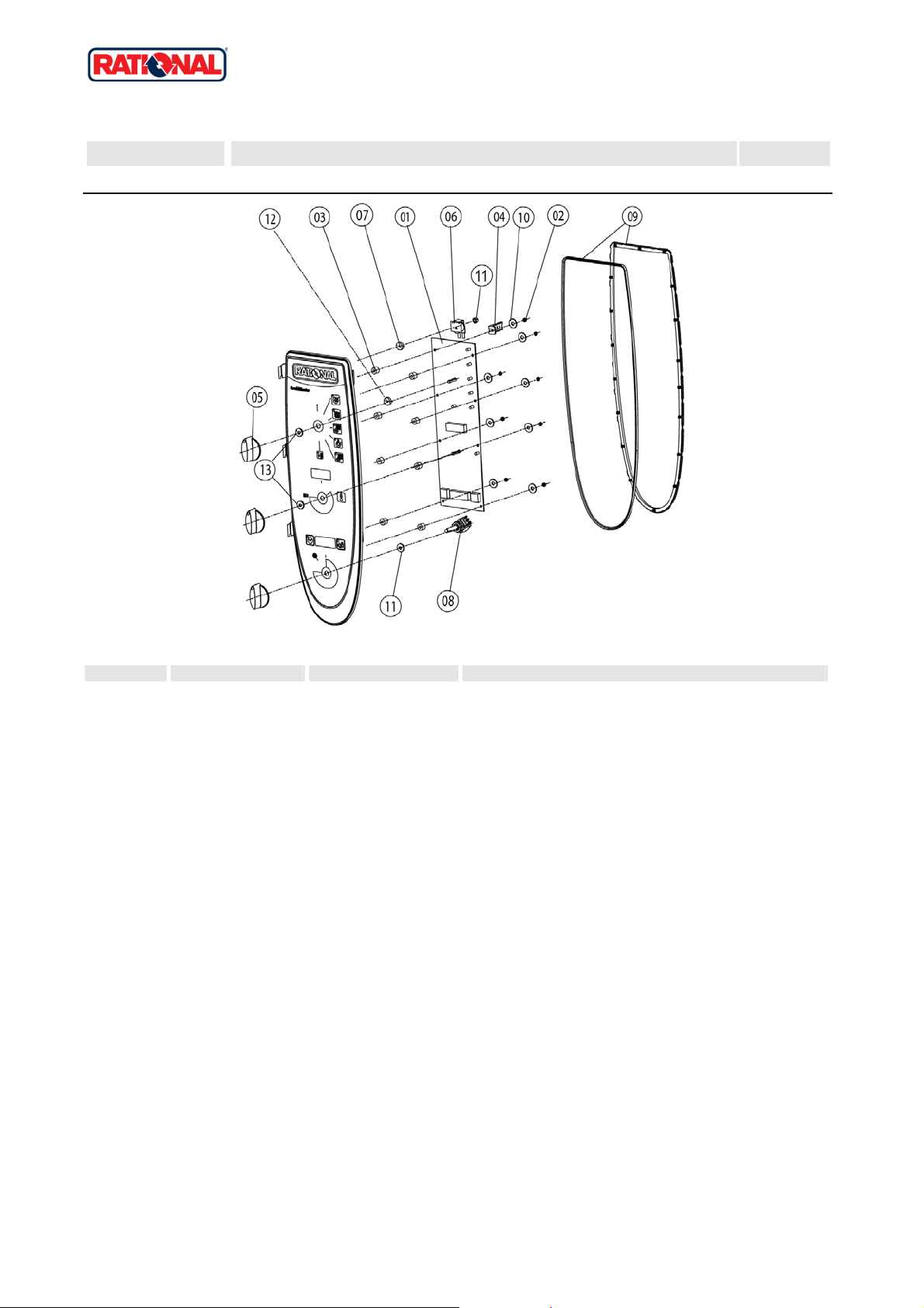
1 Control panel
1.A Control panel
X 1.A Control panel 1
Voltage 1 NAC 120V 60Hz
Item no. Part no Reference Description
1 42.00.004 Control pcb Index "ME"
2 1104.0121 He x nut M4 self locking
3 10.00.355 Spacer black
4 2020.0400 F ixing device for cable harness
5 16.00.282 Dial
6 40.02.087 Buzzer
6 3006.0107 Buzzer
7 5110.1028 Gasket poti hot air, core temperature
8 40.00.464 Potentiometer CT
9 16.00.387 Mounting device f.sealing + sealin g lip
10 1306.0218 Washer A4,3
11 1103.0122 He x nut M3 self-locking
12 5110.1029 Gasket mode switch
13 5110.1027 Distance plate for front panel
Attention! Individual parts shown might not be used in this component group!
Version 2006 4
Page 5
CM 201G
Valid as of G21ME0404 up to
G21ME0601
Gas unit
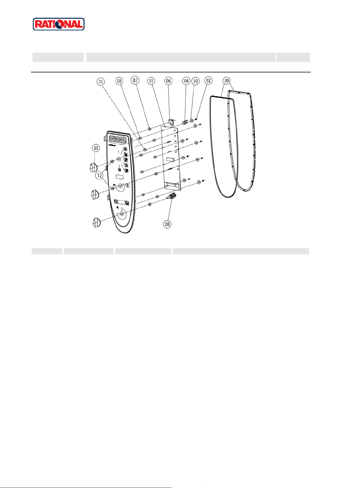
1 Control panel
1.A Control panel
X 1.A Control panel 1
Voltage 1 NAC 120V 60Hz
Item no. Part no Reference Description
1 42.00.004 Control pcb Index "ME"
2 1104.0121 He x nut M4 self locking
3 10.00.355 Spacer black
4 2020.0400 F ixing device for cable harness
5 16.00.282 Dial
6 3006.0107 Buzzer
7 5110.1028 Gasket poti hot air, core temperature
8 40.00.464 Potentiometer CT
9 16.00.387 Mounting device f.sealing + sealin g lip
10 1306.0218 Washer A4,3
11 5110.1029 Gasket mode s witc h
12 5110.1027 Distance plate for front panel
Attention! Individual parts shown might not be used in this component group!
Version 2006 5
Page 6
CM 201G
Valid as of G21ME0404 up to
G21ME0601
Gas unit
2 Electrical installation
2 Electrical installation
X 2 Electrical installation 2
Voltage 1 NAC 120V 60Hz
Item no. Part no Reference Description
A X2.A Contactor assembly
1 4007.0620 Membra ne DGC 29
2 10.00.510 Grommet 10/12/16-2
3 1106.0224 He x nut M6 self locking
5 42.00.007 External memory
6 40.01.579 Fixing clip f. pcb
7 40.01.132 Center fixation f. contactor assembly
8 1104.0801 Cage nut M4
9 10.00.243 Spacer M4x8
10 1104.0120 He x nut M4
11 10.00.112 Cable clip short
12 10.00.111 Cable clip long
14 10.00.471 Cable clip d10-12mm
15 40.00.320 Cable connection M20x1.5
16 1206.0120 Tooth lock washer A6,4
17 1106.0160 He x nut M6
18 4002.0110 Cabl e connector, junction
19 40.01.597 Power supply cable 3xAWG14
20 40.01.091 Bus cable 0.4m
20 40.00.471 Bus cable 0.8m
21 10.00.445 Hex screw M8x80
22 40.00.281 Power transformer
23 40.01.600 Insulating screw joint 2pol.
Attention! Individual parts shown might not be used in this component group!
Version 2006 6
Page 7
CM 201G
Valid as of G21ME0404 up to
G21ME0601
Gas unit
2 Electrical installation
2.A Contactor assembly
X 2.A Contactor assembly 2
Voltage 1 NAC 120V 60Hz
Item no. Part no Reference Description
1 3014.0328 Dry up protector 275°F/135°C
2 3014.0302 Hex nut M10 for dry-up protector
3 40.01.482 Safety temperature limiter 365°C
4 3014.0327 He x nut M10x1,0
5 40.00.451 Contactor MC1A 310 AH6
7 40.00.474 Cooling fan D.C.
8 10.00.238 Screw Torx 4x50
9 40.00.333 Halogen transformer
10 40.01.483 Electronic noise filter
11 40.00.592 Transformer f. cooling fan
12 1105.0120 He x nut M5
13 1305.0160 Washer A5,3x10mm
14 4001.1203 End pl ate for mounting rail
15 2620.370233 Installati on rail for Contactor 100mm
15 2620.380129 Installati on rail for Contactor 130mm
15 2816.1307 Installation rail for Contactor 140mm
16 10.00.061 Pan head screw Torx T20 M4x12
17 10.00.111 Cable clip long
18 40.01.588 Fuse SC-8A 10x38
19 40.01.487 Fuse holder 2pol
20 10.00.364 Pan head screw Torx M3x12
21 40.00.221 Cable burner blo wer
21 40.01.485 Cable burner blo wer
21 40.00.212 Cable buzzer
21 40.00.218 Cable control harness
21 40.00.230 Cable gas valve
21 40.00.249 Cable harness isolating transformer
21 40.01.542 Cable level electrode
21 40.00.219 Cable SC pump
Attention! Individual parts shown might not be used in this component group!
Version 2006 7
Page 8

CM 201G
Valid as of G21ME0404 up to
G21ME0601
Gas unit
2 Electrical installation
Item no. Part no Reference Description
21 40.00.220 Cable solenoid valve
21 40.00.237 Ground wire
X 2.A Contactor assembly 2
Voltage 1 NAC 120V 60Hz
Attention! Individual parts shown might not be used in this component group!
Version 2006 8
Page 9
CM 201G
Valid as of G21ME0404 up to
G21ME0601
Gas unit
3 Clima Plus
3 Clima Plus
X 3 Clima Plus 3
Voltage 1 NAC 120V 60Hz
Item no. Part no Reference Description
1 22.00.324 Safety valve
2 22.00.214 Hose d50x202
3 2066.0531 Hose cl amp ø56
4 2001.0124 Compression spring
Attention! Individual parts shown might not be used in this component group!
Version 2006 9
Page 10
CM 201G
Valid as of G21ME0404 up to
G21ME0601
Gas unit
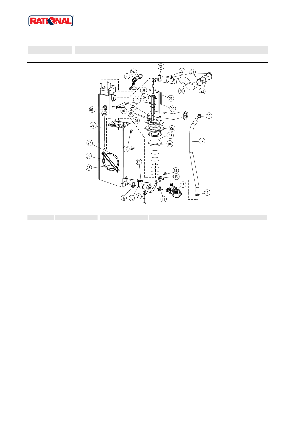
4 Steam generator, Bypass
4 Steam generator, Bypass
X 4 Steam generator, Bypass 4
Voltage 1 NAC 120V 60Hz
Item no. Part no Reference Description
A 8354.1320 X4.A Pump connection spout cpl.
B 8354.1304 X4.B
1 44.00.514 Filling level electrode 175mm
2 44.00.186 Steam generator insolated
3 72.00.010 Burner steam gen.
4 72.00.048 Insulation f. burner steam gen.
5 1104.0122 He x combination nut M4 galv
6 72.00.020 Gasket f. burner carrier
7 1105.0121 He x combination nut M5 galv
8 44.00.249 Ignition electrode steam generator
9 1104.0120 He x nut M4
10 44.00.250 Gasket f. ignition electrode
11 2066.0519 Hose cl amp 35,6mm
12 2066.0526 Hose cl amp ø46mm
13 44.00.207 Emptying pump
14 1006.0762 Hex screw M6x10
15 1306.0222 Washer A6,4x15x1,5
16 44.00.226 Fixing device f. pump steam generator
17 1106.0803 He x combination nut M6 galv
18 44.00.231 Drain hose steam generator
18 44.00.238 Drain hose steam generator
19 2066.0518 Hose cl amp 30mm
20 40.00.291 Thermocouple steam generat or
20 40.00.292 Thermocouple steam generat or
21 44.00.518 Fixing plate steam generator thermostat
22 2112.1006 Steam hose 50x7mm
23 2066.0504 Hose cl amp 40-60mm
24 2066.0506 Hose cl amp 20-32mm
25 1105.0120 He x nut M5
Venting valve for steam generator
Attention! Individual parts shown might not be used in this component group!
Version 2006 10
Page 11

CM 201G
Valid as of G21ME0404 up to
G21ME0601
Gas unit
4 Steam generator, Bypass
Item no. Part no Reference Description
26 1205.0120 Tooth lock washer A5,3
27 5012.0566 Gasket que nching chamber 0-ring
28 44.00.263 Panel for revision hole steam generator
29 44.00.264 Clamping bar for panel revision hole
30 44.00.351 Steam pipe
31 2066.0300 Hose cl amp 50-70 mm
X 4 Steam generator, Bypass 4
Voltage 1 NAC 120V 60Hz
Attention! Individual parts shown might not be used in this component group!
Version 2006 11
Page 12

CM 201G
Valid as of G21ME0404 up to
G21ME0601
Gas unit
4 Steam generator, Bypass
4.A Pump connection spout cpl.
X 4.A Pump connection spout cpl. 4
Voltage 1 NAC 120V 60Hz
Item no. Part no Reference Description
1 2118.1000 Pump connection spout
2 2120.1259 Stop plu g 10mm
3 2066.0527 Hose cl amp ø14mm
4 2066.0530 Hose cl amp ø 16.4mm
5 2062.0331 Junction pressure hose GS 10
6 4005.0101 Tie rap 145 mm
Attention! Individual parts shown might not be used in this component group!
Version 2006 12
Page 13

CM 201G
Valid as of G21ME0404 up to
G21ME0601
Gas unit
4 Steam generator, Bypass
4.B Venting valve for steam generator
X 4.B Venting valve for steam generator 4
Voltage 1 NAC 120V 60Hz
Item no. Part no Reference Description
1 2062.0332 Rece ptacle for ventilation valve SG
2 2069.0108 Ventilation valve
3 2112.1310 Form hose for ventilation of steam generator
4 2066.0506 Hose cl amp 20-32mm
Attention! Individual parts shown might not be used in this component group!
Version 2006 13
Page 14

CM 201G
Valid as of G21ME0404 up to
G21ME0601
Gas unit
5 Hot air heating
5 Hot air heating
X 5 Hot air heating 5
Voltage 1 NAC 120V 60Hz
Item no. Part no Reference Description
A 74.00.222 X5.A Burner hot air
1 74.00.170 Hot air heat exchanger below
2 74.00.175 Hot air heat exchanger top
3 74.00.234 Gasket hot air heat exchanger/interior cabinet
4 74.00.313 Mating flange heat exchanger
5 74.00.317 Gasket f. heat exchanger top
6 74.00.296 Gasket f. heat exchanger below
7 1105.0122 He x combination nut M5 V2A
Attention! Individual parts shown might not be used in this component group!
Version 2006 14
Page 15

CM 201G
Valid as of G21ME0404 up to
G21ME0601
Gas unit
5 Hot air heating
5.A Burner hot air
X 5.A Burner hot air 5
Voltage 1 NAC 120V 60Hz
Item no. Part no Reference Description
1 74.00.345 Burner welded hot air
2 74.00.230 Ignitionelectrode1 f. hot air
3 74.00.235 Ignitionelectrode2 f. hot air
4 74.00.290 Gasket electrode hot air
5 10.00.696 Allen screw M4x6 w. Precoat 85
5 10.00.060 Pan head screw Torx M4x6
Attention! Individual parts shown might not be used in this component group!
Version 2006 15
Page 16

CM 201G
Valid as of G21ME0404 up to
G21ME0601
Gas unit
6 Motor and fan wheel
6 Motor and fan wheel
X 6 Motor and fan wheel 6
Voltage 1 NAC 120V 60Hz
Item no. Part no Reference Description
1 2120.1306 Spacer SW 19x17
2 22.00.123 Flange f. motor shaft gasket
3 22.00.120 Mounting support f. gasket flange
4 22.00.083 Motor shaft gasket
5 1315.0101 Cop per washer 6x10
6 1106.0220 He x nut M6 flat
7 22.00.188 Fan wheel d340x110
8 10.00.565 Hex screw M8x20
8 1008.0763 He x screw M8x20
11 40.00.274 Fan motor
12 1108.0260 He x nut M8
12 10.00.071 Hex nut M8
12 10.00.710 Hex nut M8 w. locking
13 1208.0260 Sprin g washer B8
14 1008.1005 Square necked mushroom head bolt 8x40
Attention! Individual parts shown might not be used in this component group!
Version 2006 16
Page 17

CM 201G
Valid as of G21ME0404 up to
G21ME0601
Gas unit
7 Interior cabinet
7 Interior cabinet
X 7 Interior cabinet 7
Voltage 1 NAC 120V 60Hz
Item no. Part no Reference Description
A X7.A Interior cabinet welded
B 40.00.091 X7.B
C 22.00.297 X7.C Air baffle
C 22.00.410 X7.C
3 3024.0201 Halo gen bulb for interior cabinet 300°C
4 40.00.229 Wiring interior light
5 20.00.398 Door gasket
6 40.00.298 Meat probe sensor
6 40.02.102 Meat probe sensor
7 1315.0104 Cop per washer 16x20x1,5
8 10.00.422 Hex nut M16
9 3014.0162 Seal ing cone for thermocouple
10 3014.0163 Gasket sleeve wit h nipple
11 22.00.220 Air baffle support
12 40.01.099 Thermocouple interior cabinet (B1)
13 2005.0308 Outlet sieve
Gasket frame w. glass a. gaskets
Air baffle
Attention! Individual parts shown might not be used in this component group!
Version 2006 17
Page 18

CM 201G
Valid as of G21ME0404 up to
G21ME0601
Gas unit
7 Interior cabinet
7.A Interior cabinet welded
X 7.A Interior cabinet welded 7
Voltage 1 NAC 120V 60Hz
Item no. Part no Reference Description
1 40.00.098 Reflector f. interior light
2 4001.1248 Porcel ain connector 2-pin interior light
3 2120.1277 Base for sensor connection
4 1603.0167 Tubular rivet 3,2x0.25x10
5 10.00.041 Rivet nut M5 hexagon closed
Attention! Individual parts shown might not be used in this component group!
Version 2006 18
Page 19

CM 201G
Valid as of G21ME0404 up to
G21ME0601
Gas unit
7 Interior cabinet
7.B Gasket frame w. glass a. gaskets
X 7.B Gasket frame w. glass a. gaskets 7
Voltage 1 NAC 120V 60Hz
Item no. Part no Reference Description
1 40.00.093 Outer gasket f. interior light
2 40.00.094 Inner gasket f. interior light
3 40.00.095 Glass pane f. interior light
4 40.00.096 Gasket frame f. interior light
5 10.00.682 Phillips countersunk-head screw M5x16
Attention! Individual parts shown might not be used in this component group!
Version 2006 19
Page 20

CM 201G
Valid as of G21ME0404 up to
G21ME0601
Gas unit
7 Interior cabinet
7.C Air baffle
X 7.C Air baffle 7
Voltage 1 NAC 120V 60Hz
Item no. Part no Reference Description
1 1304.0160 Washer A4,3
2 1604.0167 Rivet 4x10
3 22.00.332 Air sucking ring f. air baffle
4 2760.1370 Latch hook for air baffle
5 40.01.289 Fixing clip core temp. cable
6 10.00.515 Rivet 3,2x5 A4
6 1603.0168 Rivet 3,2x8 A4
6 1603.0168 Rivet 3,2x8 A4
Attention! Individual parts shown might not be used in this component group!
Version 2006 20
Page 21

CM 201G
Valid as of G21ME0404 up to
G21ME0601
Gas unit
7 Interior cabinet
7.C Air baffle
X 7.C Air baffle 7
Voltage 1 NAC 120V 60Hz
Item no. Part no Reference Description
1 40.01.289 Fixing clip core temp. cable
2 1306.0218 Washer A4,3
2 1304.0160 Washer A4,3
3 1604.0167 Rivet 4x10
4 22.00.332 Air sucking ring f. air baffle
5 2760.1370 Latch hook for air baffle
6 10.00.515 Rivet 3,2x5 A4
6 1603.0168 Rivet 3,2x8 A4
Attention! Individual parts shown might not be used in this component group!
Version 2006 21
Page 22

CM 201G
Valid as of G21ME0404 up to
G21ME0601
Gas unit
8 Door
8 Door
X 8 Door 8
Voltage 1 NAC 120V 60Hz
Item no. Part no Reference Description
A 24.00.121 X8.A Door
C 8514.1307 X8.C
1 2001.0042 Loctite 24 3 10 ml
2 2001.0046 Loctite 27 2
3 24.00.136 Door handle
4 8474.1410 Door l ock
5 1005.1901 Straight pi n ø5,6x16
6 1006.0761 Hex screw M6x12
6 10.00.698 Hex screw M6x12 w. precoat 85
7 1206.0261 Spring washer B6
8 2940.1305 Door bolt
9 1008.1963 Hex socket countersunk head screw M8x16
10 2039.0309 Cover cap for door
11 1004.0665 Alle n screw M4x6
11 10.00.696 Allen screw M4x6 w. Precoat 85
12 24.00.133 Door mounting support top
13 1008.0768 Ornamenta l screw M8x16
14 1308.0160 Washer A8,4
15 24.00.145 Door bolt
16 1008.0766 Hex screw M8x30
17 1308.0162 Washer A8,4
18 24.00.048 Door bolt
19 1008.0769 Ornamenta l screw M8x30
20 2001.0109 Compression spring
21 1008.0761 Hex screw M8x25
22 1208.0260 Spring washer B8
23 24.00.216 Mounting braket f. door lock
24 1008.0752 Hex screw M5x10
24 10.00.697 Hex screw M5x10 w. precoat 85
Door catch
Attention! Individual parts shown might not be used in this component group!
Version 2006 22
Page 23

CM 201G
Valid as of G21ME0404 up to
G21ME0601
Gas unit
8 Door
Item no. Part no Reference Description
25 1305.0160 Washer A5,3 x10mm
26 10.00.099 Hex screw M8x12
27 1005.1903 Straight pi n ø5,6x12
28 1004.0906 He x socket set screw M4x8
X 8 Door 8
Voltage 1 NAC 120V 60Hz
Attention! Individual parts shown might not be used in this component group!
Version 2006 23
Page 24

CM 201G
Valid as of G21ME0404 up to
G21ME0601
Gas unit
8 Door
8.A Door
X 8.A Door 8
Voltage 1 NAC 120V 60Hz
Item no. Part no Reference Description
1 24.00.210 Inner glass pane
2 24.00.147 Sleeve for door bolt top
3 24.00.159 Door setting bolt
4 24.00.503 Fixing device f. magnet with magnet
5 24.00.187 Gasket glass pane/trolly
6 24.00.177 Pre heat mechanism f. door cpl.
7 24.00.507 Fixing device middle f.inter. glass pan e
8 24.00.700 Additional gasket f. trolly
9 24.01.259 Plastic buffer 8,1mm
10 24.01.234 Bracket right f. door floor model
Attention! Individual parts shown might not be used in this component group!
Version 2006 24
Page 25

CM 201G
Valid as of G21ME0404 up to
G21ME0601
Gas unit
8 Door
8.C Door catch
X 8.C Door catch 8
Voltage 1 NAC 120V 60Hz
Item no. Part no Reference Description
1 5012.0711 Silico ne plate for door
2 1006.1000 Stud bolt M6x75
3 1306.0550 Washer A6,6
4 1004.0904 He x socket set screw M6x10
5 1106.0160 He x nut M6
6 2001.0119 Compression spring f. door catch
7 1006.0625 Allen screw M6x70
Attention! Individual parts shown might not be used in this component group!
Version 2006 25
Page 26

Gas unit
9 Water supply, quenching box
CM 201G
Valid as of G21ME0404 up to
G21ME0601
X 9 Water supply, quenching box 9
9 Water supply, quenching
box
Voltage 1 NAC 120V 60Hz
Item no. Part no Reference Description
1 54.00.208 Exhaust pipe
2 2066.0516 Hose cl amp 60-80 mm
3 40.00.398 Thermocouple quenching
4 50.00.316 Single solenoid valve
5 50.00.139 Single solenoid valve
6 50.00.073 Water distribution vert w/o roll guide con.
7 50.00.072 Water distribution vert roll guide con.
8 50.00.275 Mounting device f. water distribution
9 50.00.086 Locking plate f. water distribution
10 50.00.078 Non return valve DW16/DN12
11 1900.0202 Water filter
12 2067.0050 Pressure hose d10mm
13 2066.0205 Hose cl amp 8-16x9 mm SW 7mm
14 8664.1301 T-fitting water connection
15 5110.1024 Gasket for G3/4" threa ded joint
16 50.00.085 Plug-in spring f. hand shower roll guide
17 54.00.237 Inspection lid f. quenching chamber
18 5012.0566 Gasket que nching chamber 0-ring
19 54.00.225 Clamping bar
20 2016.0943 Quench ing nozzle
21 2112.1307 Hose 70x5mm
Attention! Individual parts shown might not be used in this component group!
Version 2006 26
Page 27

CM 201G
Valid as of G21ME0404 up to
G21ME0601
Gas unit
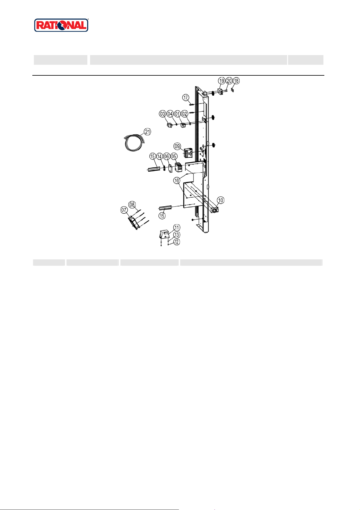
10 Hand shower
10 Hand shower
X 10 Hand shower 10
Voltage 1 NAC 120V 60Hz
Item no. Part no Reference Description
1 50.00.176 Hand shower roll guide
2 50.00.230 Connect. pipe f. hand shower roll guide
3 50.00.130 Hand shower
4 50.00.156 Clamp f. hand shower roll guide
5 1107.0100 Star lock ø4
6 50.00.135 Tulip for handshower
7 50.00.544 Mounting device f. hand sh. roll guide
8 50.00.290 Gasket f. tulip
9 50.00.297 Gasket f. tulip
11 50.00.548 Hose ø10x2x500 f. hand shower
12 50.00.537 Gasket f. connect.pipe hand shower roll guide
13 50.00.538 O-ring f. connect. pipe f. hand shower roll guide
Attention! Individual parts shown might not be used in this component group!
Version 2006 27
Page 28

CM 201G
Valid as of G21ME0404 up to
G21ME0601
Gas unit
12 Gas parts
12 Gas parts
X 12 Gas parts 12
Voltage 1 NAC 120V 60Hz
Item no. Part no Reference Description
A 70.00.068 X12.A Gas valve cpl. ND 055 RG148
B 70.00.029 X12.B
1 70.00.222 Air hose fixing device 50mm
2 70.00.221 Air hose fixing device 40mm
3 70.00.028 Blower for burner RG130
4 70.00.067 Blower for burner RG148
5 1008.0750 Hex screw M5x16
6 1305.0160 Washer A5,3 x10mm
7 74.00.310 Flange f. burner blower RG130
8 1105.0122 He x combination nut M5 V2A
9 70.00.242 Gasket f. steam gen blower RG148
10 74.00.301 Gasket f. blower burner
11 10.00.065 Countersunk screw Torx T20 M4x12
12 70.00.367 Premix chamber gas f. RG148
13 70.00.238 Premix chamber cover gas f. RG148
14 10.00.063 Pan head screw Torx T20 M4x25
15 70.00.246 Pipe gas valve-premix chamber
16 1104.0121 He x nut M4 self locking
17 10.00.064 Pan head screw Torx T20 M4x30
18 70.00.139 Corrugated hose 490mm
19 70.00.201 Corrugated hose 970mm
20 70.00.142 Corrugated hose 1200mm
21 10.00.061 Pan head screw Torx T20 M4x12
22 70.00.301 Combustion air angle pipe hot air
23 74.00.309 Gas connection manifold 3x3/4"
24 1006.0762 Hex screw M6x10
25 1306.0222 Washer A6,4x15x1,5
26 74.00.221 Automatic ignition controller
27 10.00.062 Pan head screw Torx T20 M4x20
Gas valve cpl. WND 055 RG130
Attention! Individual parts shown might not be used in this component group!
Version 2006 28
Page 29

CM 201G
Valid as of G21ME0404 up to
G21ME0601
Gas unit
12 Gas parts
Item no. Part no Reference Description
28 70.00.137 Air hose D40x900mm
29 70.00.135 Air hose D50x1100mm
30 2066.0504 Hose cl amp 40-60mm
31 40.01.581 Jumper
32 1204.0120 Tooth lock washer A4,3
33 70.00.188 Hose fitting 3/4"-3/4"
34 70.00.280 Silicone hose ø4x1,5
X 12 Gas parts 12
Voltage 1 NAC 120V 60Hz
Attention! Individual parts shown might not be used in this component group!
Version 2006 29
Page 30

CM 201G
Valid as of G21ME0404 up to
G21ME0601
Gas unit
12 Gas parts
12.A Gas valve cpl. ND 055 RG148
X 12.A Gas valve cpl. ND 055 RG148 12
Voltage 1 NAC 120V 60Hz
Item no. Part no Reference Description
1 70.00.220 Gas valve GB 055 ND (straight)
2 70.00.106 Premix disc gas
3 70.00.208 Disc premix chamber-blower RG148
4 70.00.108 Disc gas valve-premix chamber
5 70.00.260 Gas nozzle 7mm
6 70.00.261 O-ring 17x1.5
Attention! Individual parts shown might not be used in this component group!
Version 2006 30
Page 31

CM 201G
Valid as of G21ME0404 up to
G21ME0601
Gas unit
12 Gas parts
12.B Gas valve cpl. WND 055 RG130
X 12.B Gas valve cpl. WND 055 RG130 12
Voltage 1 NAC 120V 60Hz
Item no. Part no Reference Description
1 70.00.031 Gas valve GB 055 WND (lateral)
2 70.00.255 Premix chamber cover gas f. RG130
3 70.00.030 Premix chamber gas f. RG130
4 70.00.106 Premix disc gas
5 70.00.256 Disc premix chamber-blower RG130
Attention! Individual parts shown might not be used in this component group!
Version 2006 31
Page 32

CM 201G
Valid as of G21ME0404 up to
G21ME0601
Gas unit
13 Exterior cabinet
13 Exterior cabinet
X 13 Exterior cabinet 13
Voltage 1 NAC 120V 60Hz
Item no. Part no Reference Description
A X13.A Exterior cabinet
1 22.00.354 Spacer ring
1 8450.1310 Spacer ri ng
2 22.00.353 Vent cover
2 8455.1209 Vent cover
3 2022.0101 Grommet 18 mm
4 8700.0317 Floor fixin g for units
5 5006.0213 Glue for floor fi xing brackets
6 5013.0100 Edge protection profile
8 2039.0111 Foot adjustable, metal, 40 x 40
Attention! Individual parts shown might not be used in this component group!
Version 2006 32
Page 33

CM 201G
Valid as of G21ME0404 up to
G21ME0601
Gas unit
13 Exterior cabinet
13.A Exterior cabinet
X 13.A Exterior cabinet 13
Voltage 1 NAC 120V 60Hz
Item no. Part no Reference Description
1 16.00.334 Top cover
2 1003.2265 Countersunk self tapping screw 4,2x16
3 1104.0820 Snap nut 4,2mm
4 1105.0260 Cap n ut M5, high shape
5 1305.0160 Washer A5,3 x10mm
6 16.00.142 Side panel right
7 1603.0166 Rivet 3,2x7,9 CNS closed
8 16.00.143 Side panel left
9 10.00.102 Hex self tapping screw B4,2x32
10 16.00.382 Back panel
11 16.00.296 Front panel
12 2002.0107 Tension spring for front panel
13 16.00.673 Air inlet filter
14 2039.0331 Cap for service door
15 1004.2160 He x self tapping screw 4,2x16
16 16.00.330 Crossbar top
17 10.00.103 EJOT PT-screw KA 3.5x10
18 40.00.454 Door switch 1.65m
19 16.00.360 Cover f. RS232 interface
20 16.00.115 Rosette
21 16.00.338 Edge protection profile
22 16.00.358 Crossbar front panel
24 40.00.476 Exhaust channel
25 5105.1028 Gasket f. breather tube d=74mm
26 16.00.384 Bracket for door contact switch
Attention! Individual parts shown might not be used in this component group!
Version 2006 33
Page 34

CM 201G
Valid as of G21ME0404 up to
G21ME0601
Gas unit
14 Miscellaneous
14 Miscellaneous
X 14 Miscellaneous 14
Voltage 1 NAC 120V 60Hz
Item no. Part no Reference Description
1 60.21.177 Mobile oven rack for type 201,
2 1008.0760 He x screw M8x16
3 10.00.448 Phillips countersunk-head screw M5x16
4 1006.0760 He x screw M6x16
5 10.00.565 Hex screw M8x20
6 1208.0160 Tooth lock washer A8,4
7 10.00.357 Rubber plug black
8 1106.0360 Cap n ut M6, high sha pe
9 1306.0120 Washer A6,4
10 60.60.101 Castor without brake ø125mm
11 60.60.100 Castor with brake ø125mm
12 1603.0162 Rivet 3,2 x9
13 42.00.030 Memory-Stick
14 4019.0008 Sticker Electric /Danger
16 60.60.574 Positioning support f. core sensor
Attention! Individual parts shown might not be used in this component group!
Version 2006 34
 Loading...