

Raritan NOC 100, NOC 2500M, NOC 250, NOC 2500N, NOC 2500S Administrator's Manual
CommandCenter®
NOC
Administrator Guide
Release 5.4
Copyright © 2006 Raritan Computer, Inc.
CCNOC-0D-E
June 2006
255-80-5301-00

This page intentionally left blank.

D
Copyright and Trademark Information
This document contains proprietary information that is protected by copyright. All rights reserved.
No part of this document may be photocopied, reproduced, or translated into another language
without express prior written consent of Raritan Computer, Inc.
© Copyright 2006 Raritan, CommandCenter, RaritanConsole, Dominion, and the Raritan
company logo are trademarks or registered trademarks of Raritan Computer, Inc. All rights
reserved. Java is a registered trademark of Sun Microsystems, Inc. Internet Explorer is a
registered trademark of Microsoft Corporation. Netscape and Netscape Navigator are registered
trademarks of Netscape Communication Corporation. All other marks are the property of their
respective owners.
FCC Information
This equipment has been tested and found to comply with the limits for a Class A digital device,
pursuant to Part 15 of the FCC Rules. These limits are designed to provide reasonable protection
against harmful interference in a commercial installation. This equipment generates, uses, and can
radiate radio frequency energy and if not installed and used in accordance with the instructions,
may cause harmful interference to radio communications. Operation of this equipment in a
residential environment may cause harmful interference.
Japanese Approvals
Raritan is not responsible for damage to this product resulting from accident, disaster, misuse,
abuse, non-Raritan modification of the product, or other events outside of Raritan’s reasonable
control or not arising under normal operating conditions.
U
C
LISTE
For assistance in the North or South America, please contact the Raritan Technical Support Team
by telephone (732) 764-8886, by fax (732) 764-8887, or by e-mail
Ask for Technical Support – Monday through Friday, 8:00am to 8:00pm, Eastern.
1F61
US
L
I.T.E.
tech@raritan.com
For assistance around the world, please see the last page of this guide for
regional Raritan office contact information.

Safety Guidelines
To avoid potentially fatal shock hazard and possible damage to Raritan equipment:
• Do not use a 2-wire power cord in any product configuration.
• Test AC outlets at your computer and monitor for proper polarity and grounding.
• Use only with grounded outlets at both the computer and monitor. When using a backup UPS,
power the computer, monitor and appliance off the supply.
Default Login User ID/Password
The default username for CC-NOC is admin and the password is raritan. It is recommended to
change this immediately.
Rack Mount Safety Guidelines
In Raritan products which require Rack Mounting, please follow these precautions:
• Operation temperature in a closed rack environment may be greater than room temperature.
Do not exceed the rated maximum ambient temperature of the appliances (see Appendix A:
Specifications).
• Ensure sufficient airflow through the rack environment.
• Mount equipment in the rack carefully to avoid uneven mechanical loading.
• Connect equipment to the supply circuit carefully to avoid overloading circuits.
• Ground all equipment properly, especially supply connections, such as power strips (other
than direct connections), to the branch circuit.

FIGURES v
Contents
Chapter 1: Introduction .................................................................. 1
Stand-alone Appliances....................................................................................................................1
Distributed 2500 Series Appliances..................................................................................................1
CommandCenter Secure Gateway (CC-SG) ...................................................................................1
User PC Preparation.................................................................................................................................2
Remote Authentication..............................................................................................................................2
Local Authentication .................................................................................................................................2
Intended Audience............................................................................................................................2
Features Described in this Document ..............................................................................................2
Terminology/Acronyms.....................................................................................................................3
Licensing Explained..........................................................................................................................6
Infrastructure.............................................................................................................................................6
Server.......................................................................................................................................................6
Workstation...............................................................................................................................................7
Promoted Workstation .............................................................................................................................. 7
Chapter 2: General and Advanced Administration ........................ 9
Power Down CC-NOC......................................................................................................................9
Appliance Shutdown/Restart............................................................................................................9
Appliance Network Settings..............................................................................................................9
Configure Date and Time........................................................................................................................10
Configure Network Connection...............................................................................................................11
Change the ISP Gateway Address.........................................................................................................11
Outgoing Email Communication .............................................................................................................12
Change Nameserver Addresses.............................................................................................................13
Network Management Configuration..............................................................................................13
Edit Discovery Ranges............................................................................................................................13
Edit SNMP Ranges.................................................................................................................................15
Configure Scheduled Outages................................................................................................................16
Configure Pollers ....................................................................................................................................18
Manage, Unmanage, Rescan, or Delete Devices...................................................................................19
Configure Performance Thresholds........................................................................................................21
Configure Outage Report........................................................................................................................22
SNMP Reparenting Exclusion List..........................................................................................................23
Associate CommandCenter Secure Gateway (CC-SG).................................................................23
Configure a CC-SG.................................................................................................................................23
Create a CC-SG Peer via a Secure Channel..........................................................................................25
Disconnect a CC-SG...............................................................................................................................26
Delete a CC-SG......................................................................................................................................26
Map CC-SG User Groups to Local User Roles.......................................................................................26
Multi-Site Management...................................................................................................................27
Configure Event Forwarding...................................................................................................................28
Configure Trap Relaying.........................................................................................................................29
Discover a Single Device................................................................................................................30
Edit Performance Thresholds (Per Device)....................................................................................31
Administrator Tools.........................................................................................................................32
Export and Download Configuration Files...............................................................................................32
Download Log Files ................................................................................................................................ 32
Check Disk Utilization on Appliance .......................................................................................................32
Send Incident Report..............................................................................................................................33
Generate Diagnostics File.......................................................................................................................34
Establish Support Connection.................................................................................................................34
Download Data Archives................................................................................................................35
Advanced Administration................................................................................................................35
System Software & Signature Updates...................................................................................................35
Appliance Database Administration........................................................................................................39
Data Backup and Restore.......................................................................................................................39
Manage Routes ......................................................................................................................................40
Prune Unused Performance Data........................................................................................................... 41
Delete Management Settings and Data..................................................................................................42
Delete Traffic Analysis Performance Information....................................................................................42
Install CC-NOC License .................................................................................................................43
Installed Appliances List.................................................................................................................44

vi FIGURES
Chapter 3: Configuring Intrusion Detection................................. 45
Configure a Spanned or Mirrored Port...........................................................................................45
Ethernet TAP..................................................................................................................................45
Benefits ...................................................................................................................................................45
Deployment.............................................................................................................................................46
Configure Appliance Home Networks ............................................................................................46
Configure Port Scan Detection.......................................................................................................47
Enable/Disable Signature Types via Signature Profiler..................................................................49
Select Intrusion Detection Appliance(s)..................................................................................................50
Select Types of Signatures to Monitor....................................................................................................51
Load Default Signatures or Settings from Another Appliance.................................................................52
Delete Intrusion Detection Performance Data................................................................................52
Advanced Intrusion Detection Administration.................................................................................53
Manage Signatures.................................................................................................................................53
Upload Custom Signatures Tool.............................................................................................................54
Chapter 4: Configuring Windows Management............................ 55
Windows Management Instrumentation (WMI)..............................................................................55
Configure an External Windows Proxy...........................................................................................55
External Proxy Host Requirements.........................................................................................................56
Overview.................................................................................................................................................56
Download and Run ProxyInstaller ..................................................................................................56
Open Ports on External Proxy Host........................................................................................................57
Configuring the CC-NOC to communicate with the Proxy.......................................................................57
Configuring a WINS Server or LMHOSTS File .......................................................................................62
Authenticate Windows Computers .................................................................................................64
Manage, Unmanage, or Rescan Devices ...............................................................................................64
Configure Windows Performance Thresholds................................................................................65
Configure WINS Server or LMHOSTS File on 2500M ...................................................................65
Edit WINS Settings .................................................................................................................................65
Edit LMHOSTS File.................................................................................................................................67
Chapter 5: Configuring Vulnerability Scanning............................ 69
Accessing Vulnerability Scanning...................................................................................................69
Vulnerability Scan Levels........................................................................................................................70
Specify IP Addresses and Schedule the Scan........................................................................................71
Chapter 6: Configuring Notifications ........................................... 73
Enable/Disable Notifications...........................................................................................................73
Configure Event Notifications.........................................................................................................74
Add/Edit a Notification.............................................................................................................................74
Configure Notification Groups ........................................................................................................78
Add/Modify a Notification Group .............................................................................................................79
Configure Notification Paths...........................................................................................................81
Add/Edit a Notification Path....................................................................................................................81
Configure TAP Paging....................................................................................................................86
Add a new TAP Service..........................................................................................................................87
Edit Modem Parameters.........................................................................................................................88
Revert to Original Configuration.....................................................................................................88
Chapter 7: Managing Assets ........................................................ 89
Manage Assets...............................................................................................................................89
Import Assets..........................................................................................................................................89
Export Assets..........................................................................................................................................91
Map Unassociated Assets to Nodes.......................................................................................................91
Clear All Asset Records..................................................................................................................92
Chapter 8: Creating Users, Categories, Views ............................ 93
Create, Modify, Delete Users .........................................................................................................93
Add a New User......................................................................................................................................93
Edit a User..............................................................................................................................................94
Adding/Editing a Duty Schedule .............................................................................................................95
Configure Categories......................................................................................................................96
Configure Views..............................................................................................................................99
Add/Modify an Existing View.................................................................................................................100

FIGURES vii
Map Users ............................................................................................................................................101
Appendix A: Specifications ........................................................ 103
V1 Platform...................................................................................................................................103
General Specifications..........................................................................................................................103
Hardware Specifications.......................................................................................................................103
Remote Connection..............................................................................................................................103
Environmental Requirements................................................................................................................103
Electrical Specifications........................................................................................................................104
Appendix B: Troubleshooting..................................................... 105
The Raritan Support Structure......................................................................................................105
The CC-NOC’s Ability to SSH to Raritan ..............................................................................................105
Checking Appliance Database Settings .......................................................................................106
RAID Array Failure .......................................................................................................................106
The CC-NOC Services .................................................................................................................106
Discovery..............................................................................................................................................106
Capability Scanning..............................................................................................................................107
Pollers...................................................................................................................................................107
Notifications..........................................................................................................................................107
SNMP Data Collection..........................................................................................................................108
Vulnerability Scanning ..........................................................................................................................108
Events, Historic Data, and Graphs........................................................................................................108
Windows Management .........................................................................................................................108
Your Network................................................................................................................................109
Raritan Support Structure.............................................................................................................109
Contacting Raritan................................................................................................................................109
Discovery......................................................................................................................................109
Why Don’t I See the Machine Name for my Windows 2000 Systems?.................................................110
Capability Scanning..............................................................................................................................110
Scanning Interfaces..............................................................................................................................110
Re-Parenting.........................................................................................................................................111
Do the NetBIOS Node Names Match?..................................................................................................111
Are Both IP Addresses in the SNMP Interfaces Table?........................................................................111
Why Can’t My CC-NOC Manage X Service?........................................................................................112
Pollers...........................................................................................................................................112
Notifications..................................................................................................................................113
Why am I Not Receiving Notifications?..............................................................................................113
What Conditions Cause a Notification to be Sent?...............................................................................114
SNMP Data Collection..................................................................................................................114
SNMP – What it is and What it Does....................................................................................................114
Troubleshooting SNMP Data Collection................................................................................................115
GetIF.....................................................................................................................................................116
Vulnerability Scanning..................................................................................................................116
Historic Data and Graphs.............................................................................................................117
How is Performance Data Summarized?..............................................................................................117
How are Service Level Availabilities Calculated? .................................................................................117
Why isn’t SNMP Part of my Service Level Availability Calculations?....................................................117
How Do I Interpret the SNMP Graphs/Reports?...................................................................................118
Additional Support........................................................................................................................118
The Tools Discussed in this Chapter ....................................................................................................118
Documentation......................................................................................................................................118
How do I get Help?...............................................................................................................................118
Appendix C: Performance Monitoring ........................................ 121
Overview.......................................................................................................................................121
SNMP Data Collection..................................................................................................................121
SNMP Data Collection Enhancements.........................................................................................124
Windows Performance Metrics.....................................................................................................124
Leveraging Performance Data in Network Management .............................................................125
Thresholding.................................................................................................................................126
How it works .........................................................................................................................................126
SNMP Performance Metric Thresholds........................................................................................127
Windows Performance Metric Thresholds....................................................................................128
Appendix D: Setting up WMI on Target Machines...................... 129

viii FIGURES
Configuring a Windows 98/ME box for Remote WMI Management.............................................129
Configuring a Windows Proxy Details ..........................................................................................130
Registry Changes [configuration]:.........................................................................................................131
Appendix E: Managing and Responding to Intrusion Detection
Events......................................................................................... 133
How the Intrusion Detection works...............................................................................................133
Reducing False Positives with the Signature Profiler............................................................................133
Signature Profiler and the Rules Engine...............................................................................................133
Responding to Events and Notifications ...............................................................................................134
Event Categories..........................................................................................................................134
What do I do when…....................................................................................................................134
What if I have been hacked?........................................................................................................135
Security – An Elusive Goal...........................................................................................................135
Appendix F: Notification Parameters......................................... 137
Notification Parameter Substitution..............................................................................................137
Available values............................................................................................................................137
Notification:...................................................................................................................................137
Events:..........................................................................................................................................137
Assets:..........................................................................................................................................138
Appendix G: Network Traffic Overhead: Network Management’s
Necessary Evil............................................................................ 139
ICMP Pings...................................................................................................................................139
TCP Socket Reachability..............................................................................................................139
HTTP Synthetic Transaction.........................................................................................................140
SNMP Data Collection..................................................................................................................140
Additional Notes............................................................................................................................142

FIGURES ix
Figures
Figure 1 Appliance Shutdown/Restart..........................................................................................................9
Figure 2 Configure Date and Time.............................................................................................................10
Figure 3 Configure Network Connection....................................................................................................11
Figure 4 Configure Network Connection....................................................................................................12
Figure 5 Configure Outgoing Email Communication.................................................................................. 12
Figure 6 Configure Nameserver Addresses...............................................................................................13
Figure 7 Edit Discovery Ranges.................................................................................................................14
Figure 8 Edit SNMP Ranges......................................................................................................................16
Figure 9 Defining SNMP Ranges............................................................................................................... 16
Figure 10 Configuring Scheduled Outages................................................................................................17
Figure 11 Edit Scheduled Outages............................................................................................................17
Figure 12 Configure Pollers ....................................................................................................................... 18
Figure 13 Manage, Unmanage, Rescan, or Delete Devices......................................................................20
Figure 14 Device Totals.............................................................................................................................20
Figure 15 Configure Performance Thresholds...........................................................................................21
Figure 16 Configure Outage Report...........................................................................................................22
Figure 17 Navigating to Outage Report .....................................................................................................22
Figure 18 SNMP Reparenting Exclusion List.............................................................................................23
Figure 19 Associate a CommandCenter Secure Gateway.........................................................................23
Figure 20 Configure a CommandCenter Secure Gateway......................................................................... 24
Figure 21 CommandCenter Secure Gateway in Sidebar...........................................................................24
Figure 22 CommandCenter Secure Gateway in Notification Browser........................................................24
Figure 23 Associate a CommandCenter Secure Gateway.........................................................................25
Figure 24 Create a CC-SG Peer................................................................................................................ 25
Figure 25 Disconnect a CommandCenter Secure Gateway ......................................................................26
Figure 26 Delete a CommandCenter Secure Gateway.............................................................................. 26
Figure 27 Map CC-SG User Groups to Local User Roles..........................................................................27
Figure 28 Configure Event Recipients .......................................................................................................28
Figure 29 Adding Event Recipients............................................................................................................28
Figure 30 Configure Event Severities to Forward ...................................................................................... 29
Figure 31 Configure Trap Relaying............................................................................................................30
Figure 32 Specifying Trap Recipient..........................................................................................................30
Figure 33 Discover a Single Device...........................................................................................................30
Figure 34 Configure Performance Thresholds (Per-Device)......................................................................31
Figure 35 Export & Download Configuration Files ..................................................................................... 32
Figure 36 Download Log Files ................................................................................................................... 32
Figure 37 Check Disk Utilization on Appliance...........................................................................................33
Figure 38 Send Incident Report.................................................................................................................33
Figure 39 Generate Diagnostics File..........................................................................................................34
Figure 40 Establish Support Connection via SSH......................................................................................34
Figure 41 Download Data Archives............................................................................................................35
Figure 42 System Updates.........................................................................................................................36
Figure 43 Download Updates.....................................................................................................................36
Figure 44 Install Updates...........................................................................................................................37
Figure 45 View Installed Updates .............................................................................................................. 37
Figure 46 View All Updates........................................................................................................................37
Figure 47 View All Updates........................................................................................................................38
Figure 48 Appliance Database Administration...........................................................................................39
Figure 49 Download Backup Files .............................................................................................................40
Figure 50 Install Backup Files....................................................................................................................40
Figure 51 Manage Routes..........................................................................................................................41

x FIGURES
Figure 52 Add a New Network Route.........................................................................................................41
Figure 53 Prune Unused Performance Data..............................................................................................41
Figure 54 Delete Management Settings and Data.....................................................................................42
Figure 55 Delete Traffic Analysis Performance Data.................................................................................43
Figure 56 Install a new License File...........................................................................................................43
Figure 57 Installed Appliances List ............................................................................................................44
Figure 58 Ethernet TAP Deployment.........................................................................................................46
Figure 59 Selecting an Intrusion Detection Appliance for Home Network Configuration............................ 46
Figure 60 Configuring Home Network for Intrusion Detection Appliance ................................................... 47
Figure 61 Selecting an Intrusion Detection Appliance for Portscan Detection ........................................... 48
Figure 62 Configuring Portscan Detection for an Intrusion Detection Appliance........................................48
Figure 63 Selecting Intrusion Detection Appliances for Signature Profiler.................................................50
Figure 64 Selecting Signature Types.........................................................................................................51
Figure 65 Load Intrusion Detection Settings..............................................................................................52
Figure 66 Deleting Intrusion Detection Performance Data.........................................................................52
Figure 67 Selecting an Intrusion Detection Appliance for Changing Signature Set.................................... 53
Figure 68 Generating New Signature Set ..................................................................................................53
Figure 69 Selecting an Intrusion Detection Appliance for Changing Signature Set.................................... 54
Figure 70 Selecting an Intrusion Detection Appliance for Changing Signature Set.................................... 54
Figure 71 Configure an External Proxy for Windows Management............................................................58
Figure 72 Specifying proxy host information..............................................................................................58
Figure 73 Specifying proxy host information..............................................................................................59
Figure 74 Specifying proxy authentication credentials...............................................................................60
Figure 75 List of Windows Management Proxies.......................................................................................61
Figure 76Selecting Internet Protocol (TCP/IP) for WINS Settings..............................................................62
Figure 77Selecting WINS Tab....................................................................................................................63
Figure 78 Change Authentication Usernames and Passwords for Discovered Targets............................. 64
Figure 79 Manage Devices........................................................................................................................64
Figure 80 Configuring Windows Performance Thresholds.........................................................................65
Figure 81 Edit WINS Settings ....................................................................................................................66
Figure 82 WINS Server IP Address ...........................................................................................................66
Figure 83 CommandCenter NOC 2500M Options .....................................................................................67
Figure 84 Edit LMHOSTS File....................................................................................................................67
Figure 85 Vulnerability Scanning Warning.................................................................................................69
Figure 86 Type IP Addresses for Vulnerability Scanning...........................................................................71
Figure 87 Create a Vulnerability Scanning Schedule.................................................................................72
Figure 88 Notification Status......................................................................................................................73
Figure 89 Admin Status .............................................................................................................................73
Figure 90 A Configuring Event Notifications...............................................................................................74
Figure 91 Adding a New Event Notification................................................................................................75
Figure 92 Specifying an Interface/Service Rule for Event Notification.......................................................75
Figure 93 Validating an Interface/Service Rule..........................................................................................77
Figure 94 Entering Notification Recipient Information................................................................................ 77
Figure 95 Special Values for Email Subject and Text Message Fields......................................................78
Figure 96 Arranging Event Notifications.....................................................................................................78
Figure 97 Configure Notification Groups....................................................................................................79
Figure 98 Assigning a Name to a Notification Group.................................................................................79
Figure 99 Assigning Users to a Notification Group .................................................................................... 80
Figure 100 Configuring a Notification Path.................................................................................................81
Figure 101 Configuring a Notification Path.................................................................................................82
Figure 102 Configuring a User Target in Notification Path.........................................................................82
Figure 103 Configuring a Group Target in Notification Path.......................................................................83
Figure 104 Configuring an Email Target in Notification Path......................................................................83

FIGURES xi
Figure 105 Modify Notification Paths .........................................................................................................83
Figure 106 Define Escalation in Notification Path......................................................................................84
Figure 107 Configuring a User Target for Escalation in Notification Path ..................................................84
Figure 108 Configuring a Group Target for Escalation in Notification Path................................................85
Figure 109 Configuring an Email Target in Notification Path......................................................................85
Figure 110 Configuring TAP Paging ..........................................................................................................86
Figure 111 Editing TAP Service................................................................................................................. 87
Figure 112 Editing Modem Parameters .....................................................................................................88
Figure 113 Editing Modem Parameters .....................................................................................................88
Figure 114 Importing assets.......................................................................................................................90
Figure 115 Exporting assets ......................................................................................................................91
Figure 116 Mapping unassociated assets to nodes................................................................................... 91
Figure 117 Clear all asset records.............................................................................................................92
Figure 118 Managing users ....................................................................................................................... 93
Figure 119 Adding a New User..................................................................................................................93
Figure 120 Editing a User .......................................................................................................................... 94
Figure 121 Creating/Editing a new user.....................................................................................................94
Figure 122 Create a duty schedule............................................................................................................95
Figure 123 Specifying duty schedule times................................................................................................95
Figure 124 Edit, delete, or reset a duty schedule.......................................................................................96
Figure 125 Configure Categories............................................................................................................... 97
Figure 126 Configure Views....................................................................................................................... 99
Figure 127 Add/Modify Views .................................................................................................................. 100
Figure 128 Map users to views................................................................................................................101

xii FIGURES

CHAPTER 1: INTRODUCTION 1
Chapter 1: Introduction
The primary function of a CommandCenter NOC (CC-NOC) is to manage nodes in your network.
Nodes are discovered automatically if their IP address is within the managed range of addresses.
In addition to network discovery, a CC-NOC also provides service management, a database of
network information, a rules engine, a notification engine, and a web server. A CC-NOC can also
be instructed to collect statistics from your Windows systems, monitor network traffic for
intrusion attempts and bandwidth performance, and scan your systems for vulnerabilities.
Within this document, the term “CC-NOC” refers to the following models:
• CommandCenter NOC 100
• CommandCenter NOC 250
• CommandCenter NOC 2500N
• CommandCenter NOC 2500M
• CommandCenter NOC 2500S
All configuration tasks are performed on a CC-NOC 100, CC-NOC 250, or CC-NOC 2500N.
Note: When information is related to a particular model, it will be explicitly noted.
Stand-alone Appliances
A CC-NOC can operate in a stand-alone environment where the appliance itself provides
complete functionality, for example, network discovery, polling, windows management, traffic
analysis, vulnerability scanning, and intrusion detection on one box.
These CC-NOC appliances can operate in a stand-alone environment and typically are deployed
in smaller networks or satellite offices:
• CC-NOC 100
• CC-NOC 250
For instructions on deploying and configuring a CC-NOC 100 or CC-NOC 250, see Raritan’s
CommandCenter NOC Deployment Guide.
Distributed 2500 Series Appliances
A CC-NOC can also operate in a distributed environment where the functionality, for example,
network discovery, polling, windows management, traffic analysis, vulnerability scanning, and
intrusion detection is dispersed among different appliances. These CC-NOC appliances can
operate in a distributed environment:
• CC-NOC 2500N: Used for configuration of other appliances, network discovery, polling,
vulnerability scanning, and outages.
• CC-NOC 2500M: Used for Windows Management.
• CC-NOC 2500S: Used for Intrusion Detection and Traffic Analysis.
For instructions on deploying and configuring a CC-NOC in a distributed environment, see
Raritan’s CommandCenter NOC Deployment Guide.
Note: A CC-NOC 2500N can be deployed by itself without a CC-NOC 2500M or CC-NOC 2500S
if the functionality offered by those appliances is not needed.
CommandCenter Secure Gateway (CC-SG)
A CC-SG provides single-point access and control for managed Raritan devices, target servers
and infrastructure devices. A CC-NOC can be deployed in conjunction with a CC-SG. Please see
Raritan’s CommandCenter Secure Gateway Administrator Guide for initial instructions on how to
configure the CC-SG to register for CC-NOC events and to enable the exchange of notifications
between the two appliances.

2 COMMANDCENTER NOC ADMINISTRATOR GUIDE
User PC Preparation
To access CC-SG and any targets managed by CC-SG, the browser must have the correct version
of Sun JRE, such as rev 1.4.2.05. See Compatibility Matrix under Firmware Upgrades for CC-
SG on
For CC-SG, pop-up blockers should be disabled as well as any firewall software such as XP SP2
that is enabled by default.
www.raritan.com/support for details.
Remote Authentication
CC-NOC users can be authenticated remotely by CC-SG to provide an enhanced seamless mode
of operation and Single Sign-on (SSO) access to CC-SG targets. With one-click access to CC-SG
and SSO access to targets, a CC-NOC user can move easily between systems.
Mapping of User Groups
With remote authentication, all CC-NOC logins will be securely routed to and resolved by CCSG for remediation. The CC-NOC receives the CC-SG user groups the CC-NOC user is a
member of and maps these groups to any of its local groups, that is, Admin, User, Executive. If a
user belongs to more than one group, the highest privileged group will be used. When a CC-NOC
user accesses a CC-SG target, the access rights, permissions, and policies are based on their user
group membership.
Note: Before mapping the groups on CC-NOC, the user groups must have already been created
on CC-SG or imported from an external authentication server, such as Active Directory.
Local Authentication
By default, CC-NOC users will be locally authenticated if remote authentication is not configured.
Local authentication is also used if remote authentication is configured but the CC-SG is
unavailable or if the password was incorrect.
If “local authentication” is used, then CC-NOC users will have to login to CC-SG to gain access
to targets. They will be prompted for a CC-SG login and password, which will be checked against
the local CC-SG user database.
Note: The admin account on CC-NOC is always authenticated locally, regardless where all other
users are authenticated.
Intended Audience
Three types of users (Administrator, User, Executive User) can access CC-NOC. This document
is intended for users who assume an Administrator role. Administrators perform configuration
tasks on a CC-NOC 100, CC-NOC 250, or CC-NOC 2500N, such as configuring intrusion
detection, windows management, vulnerability scans, etc. Tasks that are available to users with a
User or Executive User role are described in Raritan’s CommandCenter NOC User Guide, which
describes tasks such as viewing intrusion detection events, window management events, etc.
Administrators can also perform all tasks that are available to a User or Executive User.
Features Described in this Document
These features are covered in the following chapters:
• Remote Device Monitoring and Polling (automatic discovery of devices, servers,
workstations)
• Single device Discovery
• Traffic Analysis
• Intrusion Detection
• Windows Management of Servers, Workstations via Windows Management Instrumentation
(WMI)

CHAPTER 1: INTRODUCTION 3
• Vulnerability Scanning
• Event Viewing and Searching
• Performance Monitoring per category or device
• Integration with CC-SG where CC-SG is notified of events within the subscribed discovery
range.
• Scheduled Outages
• User, Views, and Category Configuration
• License Upload
• Event, Outage Notification
• Asset Management
• Reports (Outage, Availability, Inventory, Delta Inventory, Vulnerability, Security, SNMP)
• Tools – Network Tools (ping host, port test, trace route to host, profile route to host)
• Tools – Admin Tools (export & download configuration files, download log files, check disk
utilization, send incident report, generate diagnostics file)
• Advanced Admin - Support Tools (Appliance Health, Restore to Factory Defaults,
Backup/Restore Capabilities)
Terminology/Acronyms
Terms and acronyms found in this document include:
• Assets – capital assets in an organization can be tracked. Tracking your assets is useful for
keeping abreast of equipment repairs as well as network or system related moves, additions,
or changes. Asset inventory tracking facilitates generating on-demand reports of hardware
and software to enable greater productivity, financial accountability, and end-user satisfaction.
Asset records can be created manually, imported from a pre-existing list, and exported to a
CSV file for Excel record keeping. Assets can also be associated with a discovered node in
your network.
• CommandCenter Secure Gateway (CC-SG) – single-point access and control for your
managed Raritan devices, target servers, and other network infrastructure devices connected
to CC-SG.
• CSV – comma-separated value files are simple database files that can be easily imported into
a spreadsheet or database program so that you can generate custom reports. This export
functionality is available from any view of the Event Browser.
• DHCP – (Dynamic Host Configuration Protocol). A TCP/IP protocol that dynamically
assigns an IP address to a computer.
• DNS – (Domain Name System). An Internet service that translates domain names into IP
addresses.
• Duty Schedule – is a schedule that reflects a user’s work hours. When a duty schedule is
defined for a user, notifications will be sent to that user only if it occurs within the time frame
that is specified in the duty schedule.
• Events – events include SNMP traps which can be forwarded to third-party tools (HP
OpenView). Events also are generated by components of the Windows operating system and
are recorded in the Events log, for example, Netlogin service, login failures, Windows
Installer. Events are records of significant occurrences in your network, on your systems, or
within the CC-NOC. An event is either outstanding, that is, not addressed nor acknowledged.
The Events Browser allows you to gain insight as to what is going on in the network, whether
it is network management, intrusion detection, or Windows management. Events have
severities – critical, major, warning, normal, cleared, or indeterminate. Intrusion Detection
Events have categories, for example, successful admin privilege gain, and Denial of Service.
Events can be exported in a CSV format for Excel. When an event is triggered, it can send a
notification to a recipient if configured for that recipient. Events can be queried and the
queries can be saved. A CC-NOC allows you to threshold events as well.

4 COMMANDCENTER NOC ADMINISTRATOR GUIDE
• ICMP – (Internet Control Management Protocol) ICMP is used by the CC-NOC to discover
devices in your network and is documented in
RFC 792.
• In-band – going through the TCP/IP network to control a target by accessing the target
directly. KVM, Serial, and Generic devices can be accessed via these in-band applications:
RemoteDesktop Viewer, SSH Client, VNC Viewer.
• Intrusion Detection – monitors and analyzes system events for attempts to access system
resources in an unauthorized manner.
• Inventory – see Assets.
• NetBIOS – Network Basic Input/Output System is a program that allows applications on
different computers to communicate within a local area network. It was created by IBM for
its early PC Network, later adopted by Novell and Microsoft. NetBIOS is used in Ethernet,
token ring and Windows NT networks. It does not support a routing mechanism, so
applications communicating on a wide area network must use another "transport mechanism"
(such as TCP/IP) rather than, or in addition, to NetBIOS.
• Network Management – proactively monitors, collects, and maintains all devices and
services on a network.
• Notices – see Notifications.
• Notifications – a notice that is sent to one or more recipients via email, pager, etc. and is
based on an event being triggered. A CC-NOC provides default notifications. You can
control the content of a notification message. A CCNOC evaluates each event against the
configured notifications rules and if it matches one or more rules, a notification is sent. To
receive a notification, a user has to be added to a notification group. Notices can be
outstanding or acknowledged.
• NFS – (Network File System) Standard for accessing files on a remote computer appearing as
a local volume.
• Outage – instances where successive attempted polls of a given service have timed out and a
“node lost service” event was created. Each entry is assigned a unique Outage ID, a
sequential numeric identifier to uniquely identify a given outage. That ID, coupled with the
node label for the node experiencing the outage, the address of the impacted interface, the
service name, and the time the outage occurred are all tracked within the Outages Browser.
At the onset of an outage, all calculations for reporting purposes, for example, Availability
calculations in the Web Console and Availability Report reflect the current service as down
until a future poll is successful. When a service experiencing an outage is successfully polled,
a “node regained service” event will terminate the outage and assign an “Up” date and
timestamp, which is used as the end of the outage for service level availability calculations.
• Out-of-band – using applications such as Raritan Remote Console (RRC), Raritan Console
(RC), or Multi-Platform Client (MPC) to correct or troubleshoot a KVM or serial managed
target in your network..
• Pollers – programs that
collect service information from infrastructure devices and servers,
for example, web, NTP, and email and create service down messages.
• Port Scan – is the probing for openings and availabilities in a network. Attackers generally
use port scanning utilities to probe targets and make a list of all open ports on a device. They
will send specific attacks to open ports hoping to exploit a vulnerability on the target. Port
scanning is detectable by monitoring traffic on the target machine. Scan Level 1 Vulnerability
Scanning uses port scanning methods to search target systems for open ports. However,
normal and legitimate activity, such as DNS and NFS, often resembles the activity of an
attacker executing a port scan against a target and may produce false-positive port scan
events. Those servers performing those services should be excluded from port scanning
activity.
• Proxy host – a system that facilitates connectivity between the CC-NOC and your
managed Windows servers and workstations. The proxy forwards WMI data from the servers
and workstations to the CC-NOC.
• Signature – a fingerprint of network traffic that signals an attack.
• SMB – (Server Message Block) The communications protocol used by Windows-based
operating systems to support sharing of resources across a network to discover systems.

CHAPTER 1: INTRODUCTION 5
• SSO – Single Sign-On. With Single Sign-on (SSO) access to CC-SG targets, CC-NOC users
can connect to targets seamlessly, without having to sign onto CC-SG as long as remote
authentication has been configured.
• System Vulnerabilities – unpatched systems, older known vulnerable server daemons on
your system that can be exploited by harmful network traffic.
• TAP – (Telocator Alphanumeric Protocol) A standard protocol enabling modems to send text
messages to pager systems. The CC-NOC can use TAP services to send notifications as text
messages to pagers.
• Users – a CC-NOC has these three types of users:
Administrators who have configuration access to the machine.
Users who have access to everything on a CC-NOC except administrative configuration.
Executive Users who have read-only access to only a few key reports that show the network
health at a high level.
• Views – the combination of categories, for example, Database Servers, Routers, Email
Servers, and Network Interfaces that users will see when logging into a CC-NOC. Views are
customizable and provide a way to map users to the categories that they are most interested in.
• Vulnerability Scan – the CC-NOC can be configured to scan for vulnerabilities, for example,
unpatched systems and older known vulnerable server daemons within a network. Harmful
traffic can be exploited by intruders to gain access to restricted information, can alter the flow
of data through your network, or even disable important services on your network.
Vulnerability scanning provides this type of information about your network
devicesdetection and diagnosis of vulnerabilities, deep detection of all open ports and
services, and logging of all available information that may benefit intruders. Scanning for
vulnerabilities assists administrators in resolving security concerns. For example, an
administrator may decide to apply patches and software updates to fix known security holes,
shut down unwanted or unnecessary services, remove access to sensitive information in your
network, or change security settings and passwords to make them more difficult to crack. For
more information on vulnerabilities, including CVE entries, go to
http://www.cve.mitre.org.
• WMI – (Windows Management Instrumentation) WMI, also known as WBEM, is
Microsoft’s technology for providing a consistent systems management interface to their
platform.

6 COMMANDCENTER NOC ADMINISTRATOR GUIDE
Licensing Explained
As devices are discovered in your network, data is collected from the device and the device is
then assigned a license. License types include Infrastructure, Server, Workstation, and Promoted
Workstation. Administrators can change a license from one type to another. The following
explains each license type.
Infrastructure
In order for a device to be assigned an infrastructure license, it must be discovered as a node and
support one of the following "infrastructure" level services:
FTP SMTP Oracle
DHCP LDAP Sybase
DNS MSExchange Informix
NotesHTTP Citrix SQLServer
HTTP-Management DominoIIOP MySQL
HTTPS Router Server
IMAP Switch-Hub POP3
Postgres
An infrastructure device is eligible for the following functionality:
• Capability scans once every 24 hours for new services and/or inventory information
• Service availability polling
• SNMP performance data collection
• SNMP performance thresholding
You can transition a device with an Infrastructure license to any of the following licensed states:
• Workstation
• Server (if the device is a Windows system which supports WMI)
• Promoted Workstation
• Unmanaged
Server
Only Windows systems which support Windows Management Instrumentation (WMI) are
eligible to be assigned a
server system based on its operating system role retrieved via WMI to be auto-licensed as a server.
A server device is eligible for the following functionality:
• Capability scans once every 24 hours for new services and/or inventory information
• Service availability polling
• SNMP performance data collection
• Windows performance data collection
• SNMP performance thresholding
• Windows performance thresholding
You can transition a device with a Server license to any of the following licensed states:
• Workstation
• Infrastructure (if the device is a node)
• Promoted Workstation
• Unmanaged
Server license. In addition to supporting WMI, the system must be a

CHAPTER 1: INTRODUCTION 7
Workstation
A Workstation license can be assigned to any type of device, be it a Windows or non-Windows
system. For example, a Linux box which is discovered as a node and which does not support any
of the infrastructure services will be assigned a Workstation license. Similarly, a desktop
Windows system will be assigned a Workstation license.
A workstation device is eligible for the following functionality:
• Capability scans once every 24 hours for new services and/or inventory information
You can transition a device with a Workstation license to any of the following licensed states:
• Server (if the device is a Windows system which supports WMI)
• Infrastructure (if the device is a node)
• Promoted Workstation
• Unmanaged
Promoted Workstation
Promoted Workstation licenses provide a mechanism for you to obtain additional polling and
performance data from a troublesome device on a temporary basis without taking up a Server or
Infrastructure license. The only way for a device to be assigned a Promoted Workstation license
is to assign the license through the web user interface. There are a total of five promoted
workstation licenses available with a CC-NOC appliance.
A promoted workstation device is eligible for the following functionality:
• Capability scans once every 24 hours for new services and/or inventory information
• Service availability polling
• SNMP performance data collection
• Windows performance data collection
• SNMP performance thresholding
• Windows performance thresholding
You can transition a device with a Promoted Workstation license to any of the following licensed
states:
• Workstation
• Server (if the device is a Windows system which supports WMI)
• Infrastructure (if the device is a node)
• Unmanaged

8 COMMANDCENTER NOC ADMINISTRATOR GUIDE
CHAPTER 2: GENERAL AND ADVANCED ADMINISTRATION 9
Chapter 2: General and Advanced Administration
Power Down CC-NOC
If running CC-NOC on the V1 platform and if it loses AC power while it is up and running, the
V1 unit remembers its last power state. Once AC power is restored, the V1 unit automatically
reboots. However, if a V1 unit loses AC power when it is turned OFF, the V1 unit will remain
powered off when AC power is restored.
Important: Do not hold the POWER button for four or more seconds to forcibly
power down CC-NOC, particularly when CC-NOC is up and running. The
recommended way to power down CC-NOC is to use the following procedure.
To power down the CC-NOC:
1. Remove the bezel and firmly tap the POWER button.
2. Wait for approximately one minute while CC-NOC gracefully powers down. You can
monitor the progress on the console that is attached to the KVM port.
3. If removing the AC power cord, let the power down process completely finish before
removing the power cord. This is required for CC-NOC to complete all transactions, close the
databases, and place the disk drives into a safe state for power removal.
Appliance Shutdown/Restart
The System Shutdown and System Restart buttons are one way that your CC-NOC can be shut
down or restarted. You can also shutdown and restart a CC-NOC while using a serial connection
– see Raritan’s CommandCenter NOC Deployment Guide. While the CC-NOC is designed to be
an appliance, it must store information about your environment in a local database. Thus, it
should be treated with the same sensitivity as a database server. Loss of power or hard shutdowns
of the device can result in database corruption and data loss.
1. Click on the Admin tab in the top navigation bar.
2. Click either System Shutdown or System Restart.
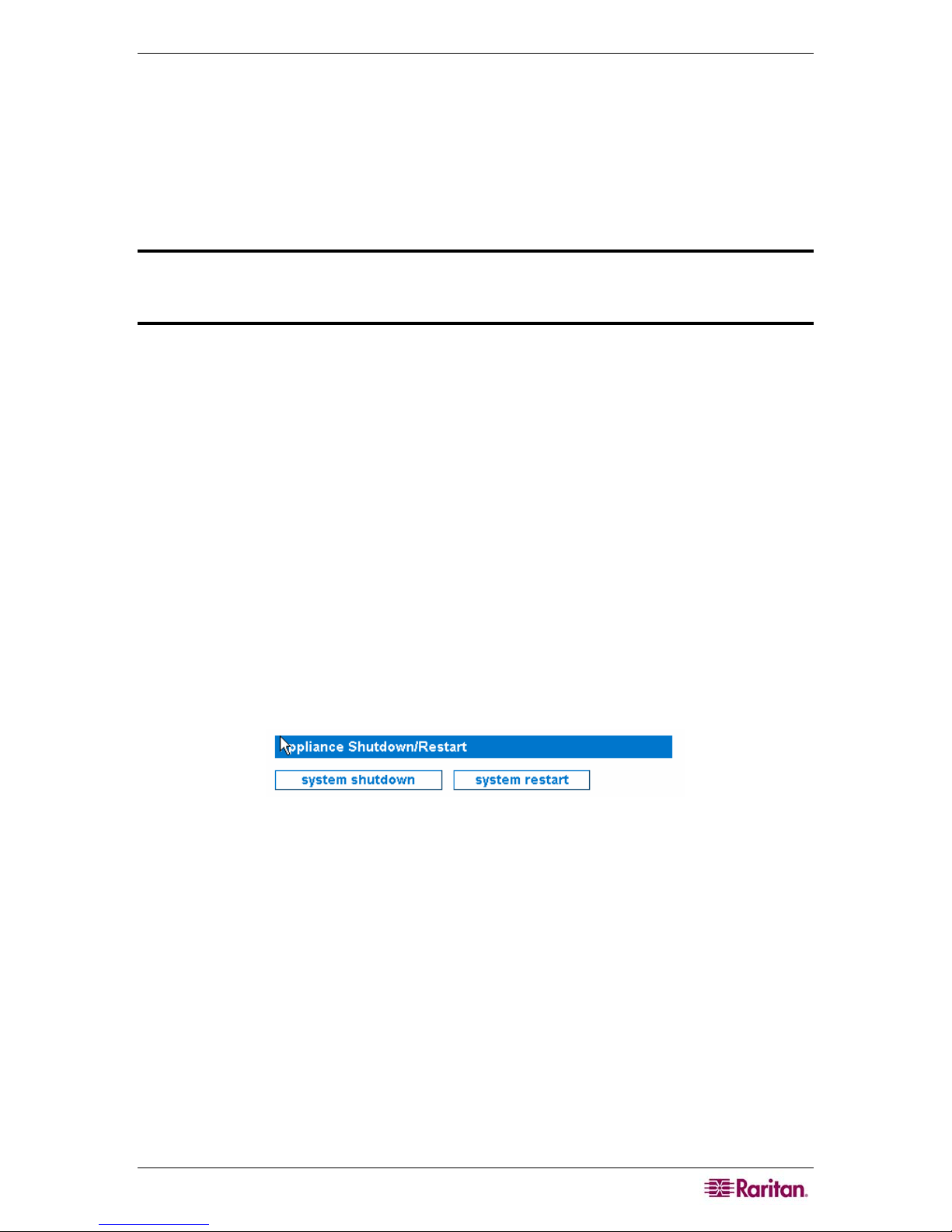
Figure 1 Appliance Shutdown/Restart
Typically, these options are used if you experience a loss of power and need to shutdown the
device while still running off a backup energy source. Contact Technical Support if you have
additional questions regarding these options or your particular situation.
Appliance Network Settings
These are the network settings that can be revisited since they were initially configured with the
serial connection and the First-Time Configuration Wizard – see Raritan’s CommandCenter NOC
Deployment Guide:
• Date and Time
• Network Connection
• ISP Gateway
• Email Communication
• Nameserver Address
10 COMMANDCENTER NOC ADMINISTRATOR GUIDE
Configure Date and Time
This page allows you to modify the current time zone and set the local time or configure a
network time protocol (NTP) server with which to synchronize the local time.
Note: If a CC-NOC 250 or 2500N is powered down for more than six hours, upon booting back
up, you will be asked to validate if the time settings are correct.
1. Click on the Admin tab in the top navigation bar.
2. Click Appliance Network Settings.
3. Click Configure Date & Time.
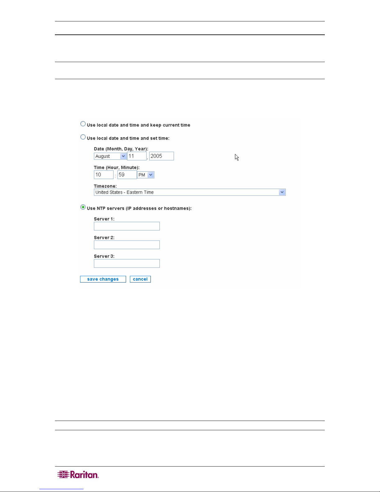
Figure 2 Configure Date and Time
4. Click the radio button Use local date and time and keep current time to leave the local
time as it is.
5. To set the local time on the CC-NOC, click the radio button Use local date and time and set
time. The time will be reset when you continue to the next step.
6. Click the drop-down arrow and select your time zone from the select box. The list is sorted
first by country (two character code), then an order within the country that makes some
geographical sense, and puts the most populous zones first, where that does not contradict the
geographical listing. Please select the zone that is nearest to your location.
7. Click Use NTP servers to turn on the NTP client. NTP is a network service that is used to
synchronize times between computers on a network. You will be required to provide at least
one NTP server if you select this option. If Use NTP servers is currently selected and you
would like to stop using the NTP client, choose either of the two options above depending on
whether or not you want to keep the current time or reset the time.
Note: If you select Use NTP servers, you should install a NTP server in your environment.
8. Click save changes.
CHAPTER 2: GENERAL AND ADVANCED ADMINISTRATION 11
Configure Network Connection
This page allows you to change the fixed IP address associated with this appliance. This IP
address was configured when setting up the initial configuration using a serial connection – see
Raritan’s CommandCenter NOC Deployment Guide.
The CC-NOC mimics the traffic generated by a user trying to access various services throughout
the network. This mandates that the CC-NOC also has a network address and other supporting
information to connect to other network devices. DHCP is NOT an alternative, as other devices
will always need to know exactly what address the CC-NOC is using.
Note: Be careful when using this interface as you can render the appliance unreachable via the
network by your users as well as by Technical Support.
1. Click on the Admin tab in the top navigation bar.
2. Click Appliance Network Settings.
3. Click Configure Network Connection.
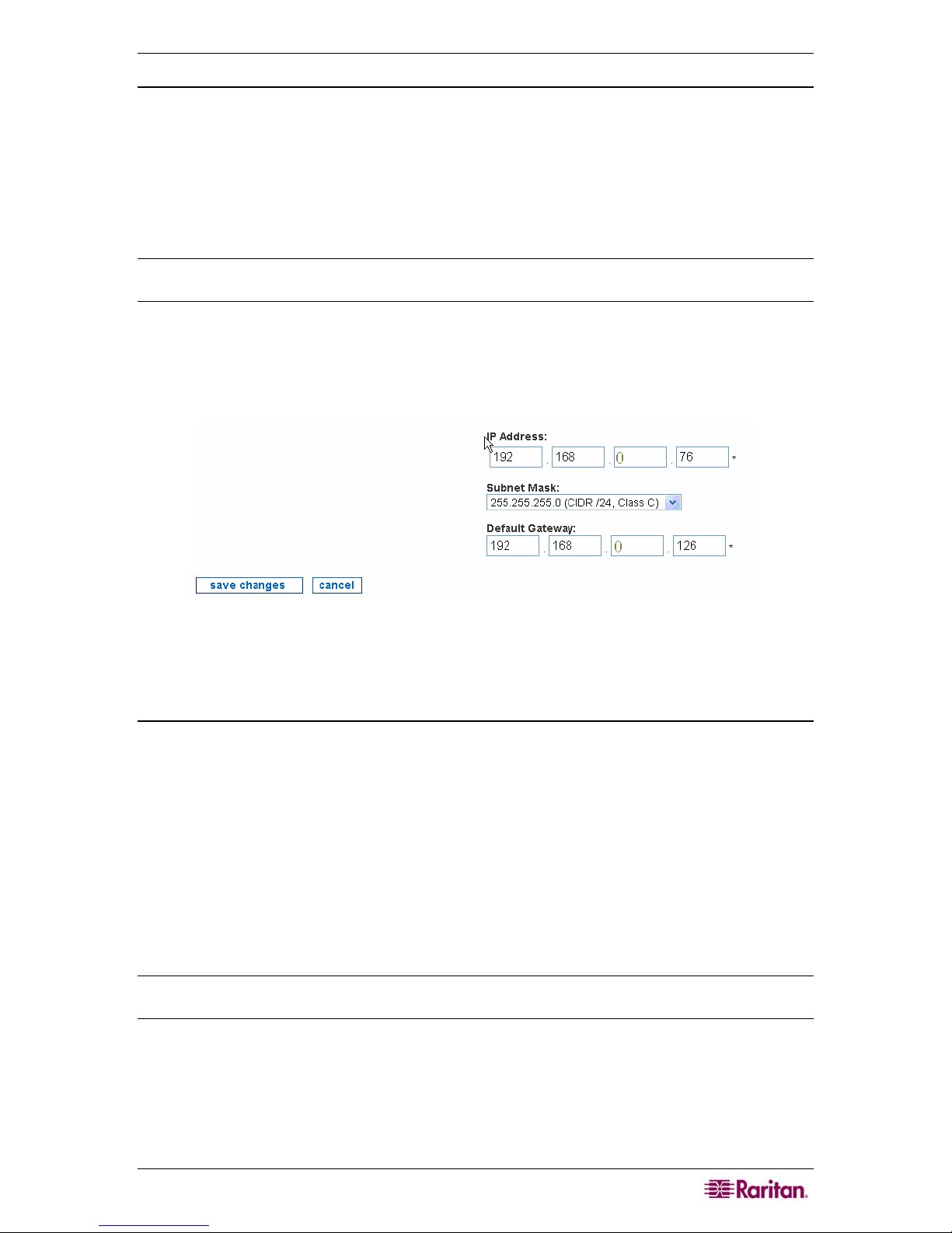
Figure 3 Configure Network Connection
4. Type network settings, such as TCP/IP address, network mask, and default gateway.
5. Click save changes.
Change the ISP Gateway Address
This page provides a way to manipulate the address monitored for inclusion in the Internet
Connectivity category. The CC-NOC handles your ISP gateway as a special case. If configured
here, your ISP gateway can be monitored for availability and reported on independently. If
applicable, specify the TCP/IP address of your gateway. If you do not have this information, your
ISP should be able to provide it or you can get it by tracing the route to the internet from a
machine on the managed network.
• UNIX Machine: Run
or DNS name that is outside of your local network and appears to belong to your ISP.
Consider the possibility of WAN interfaces showing up in this trace.
• Microsoft Windows Machine: Run
address or DNS name that is outside of your local network and appears to belong to your ISP.
Note: Note that this field is not required. If configured, the ISP gateway takes one infrastructure
license. Type an address of 0.0.0.0 if you do not wish to supply an ISP address.
traceroute www.yahoo.com and look for the first TCP/IP address
tracert www.yahoo.com and look for the first IP
1. Click on the Admin tab in the top navigation bar.
2. Click Appliance Network Settings.
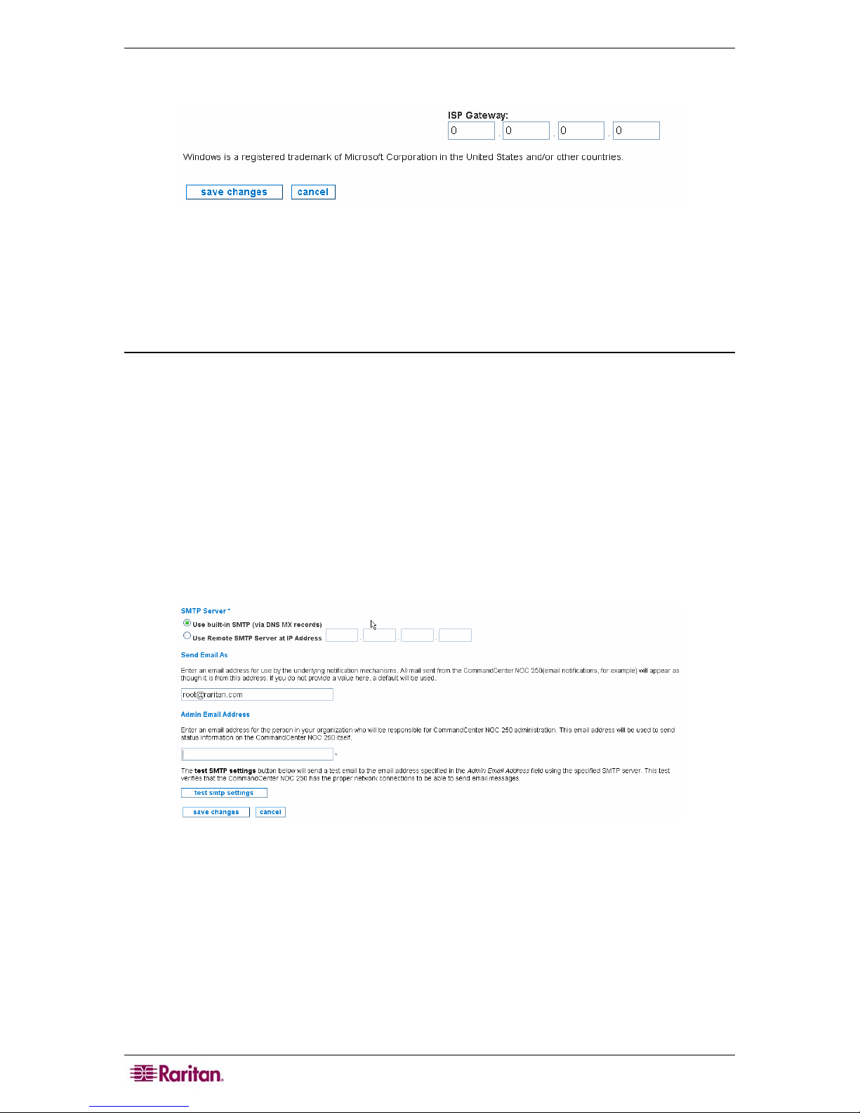
12 COMMANDCENTER NOC ADMINISTRATOR GUIDE
3. Click Change the ISP Gateway Address.
Figure 4 Configure Network Connection
4. Type the IP address of the ISP gateway or type an address of 0.0.0.0 if you do not wish to
supply an ISP address.
5. Click save changes.
Outgoing Email Communication
This page provides an interface to change the From: email address in notifications, as well as the
SMTP relay settings. These settings affect how the CC-NOC communicates with you. Keep the
information current and make sure you use valid email addresses to ensure correct status
information reaches the administrator.
To send email notifications, the CC-NOC needs to know how to send email. If allowed, the CCNOC will use its local SMTP service to send email. Some networks, however, will not accept
email from unknown sources. If this is the case, please provide the IP address of an SMTP server
below.
1. Click on the Admin tab in the top navigation bar.
2. Click Appliance Network Settings.
3. Click Outgoing Email Communication.
4. To send email notifications, the CC-NOC needs to know how to send email. If allowed, the
CC-NOC will use its local SMTP service to send email. Some networks, however, will not
accept email from unknown sources. If this is the case, provide the IP address of an SMTP
Server in the proper field and select the proper Use section.
5. The email address specified in Send Email As details the email address the underlying
notification mechanisms will use. All mail sent from the CC-NOC, for example, email
notifications will appear as though it is from this address. If you do not provide a value here,
a default will be used (root@
6. The admin email address specified in Admin Email Address should be the email address of
the person in your organization who will be responsible for CC-NOC administration. This
Figure 5 Configure Outgoing Email Communication
localhost.com).
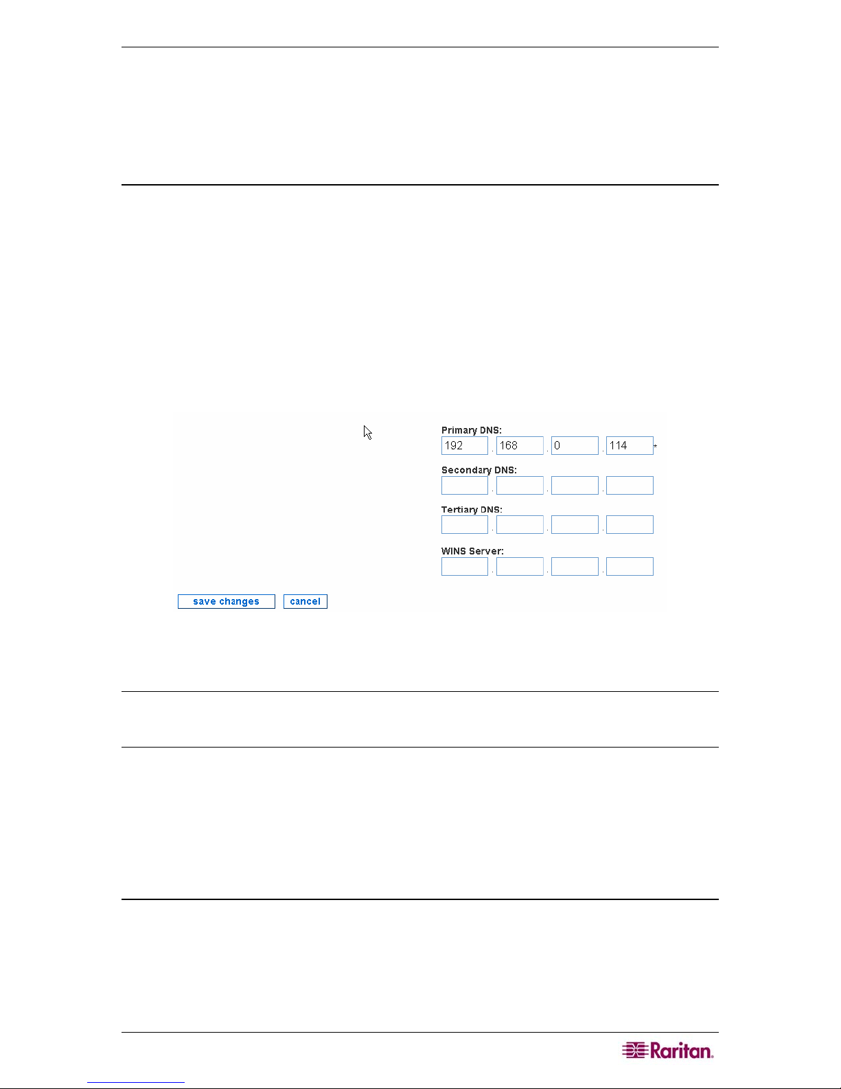
CHAPTER 2: GENERAL AND ADVANCED ADMINISTRATION 13
email address is a required field and will be used to send status information on the CC-NOC
itself.
7. Clicking test SMTP settings sends a test email to the email address specified in the Admin
Email Address field using the specified SMTP server. This test verifies that the CC-NOC
has the proper network connections to be able to send emails.
8. Click save changes.
Change Nameserver Addresses
This page allows you to configure the addresses of your DNS (up to 3) and/or WINS servers.
DNS servers allow systems to translate IP addresses into meaningful names. Please type at least
one DNS server that the CC-NOC can reach efficiently. Place your fastest local servers near the
top of the list.
WINS servers are used in NetBIOS and Windows networking environments to resolve NetBIOS
names across subnet boundaries. If you are managing several subnets that contain machines with
NetBIOS names and have a WINS server that manages the names of the machines, please type
the address of the WINS server in the spaces provided.
1. Click on the Admin tab in the top navigation bar.
2. Click Appliance Network Settings.
3. Click Change Nameserver Addresses.
Figure 6 Configure Nameserver Addresses
4. Type addresses for primary (required), secondary, tertiary DNS servers, and WINS server.
Note: The WINS Server that you can specify here is used by a CC-NOC 100, CC-NOC 250, or
CC-NOC 2500N. This is a separate WINS server that can be configured for a CC-NOC 2500M –
please see
Chapter 4: Configuring Windows Management for additional information.
5. Click save changes.
Network Management Configuration
This page allows you to configure features that affect what network devices you manage and how
you manage them. Network management proactively monitors, collects, and maintains all devices
and services on a network.
Edit Discovery Ranges
This page allows you to modify your initial configuration settings, see Raritan’s CommandCenter
NOC Deployment Guide, determining which specific addresses or address ranges should or
should not be included for discovery. Once discovered, each system is cataloged as either a
Server, Infrastructure, Workstation, or Promoted Workstation device. In this page, you can also
set a flag that determines whether or not any newly discovered devices are automatically licensed
and managed or not. CC-NOC discovers devices via this discovery range, single device discovery
– see section
Discover a Single Device later in this chapter, incoming traps, and through the
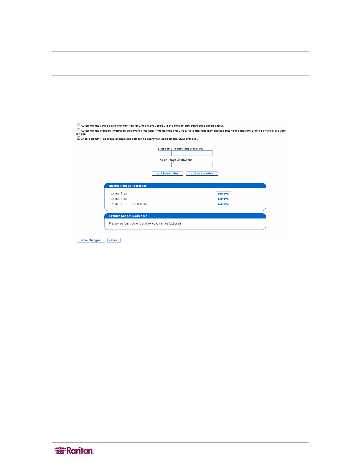
14 COMMANDCENTER NOC ADMINISTRATOR GUIDE
WMI management range – see Specifying Windows Management Ranges in Chapter 4:
Configuring Windows Management for details. Typically, you would want the discovery range
specified here to overlap with the WMI management range.
Note: A CC-NOC discovers devices in the network using ICMP protocol. Once discovered,
further data (for example, operating system) is collected from the device and the device is then
assigned a license, that is, Infrastructure Device license, Server license, or Workstation license.
1. Click on the Admin tab in the top navigation bar.
2. Click Network Management Configuration.
3. Click Edit the Discovery Ranges.
Figure 7 Edit Discovery Ranges
4. Type IP addresses or ranges and click either add to includes or add to excludes– this will
add them to the appropriate list. You can only add one IP or range at a time. If you would like
to remove one from the list, click remove to the right of its listing. When you are done, click
save changes. Use these examples:
• To discover a range, type the first address and the last address and click add to includes.
Ranges may span multiple networks. If there are any ranges or addresses that cannot or
should not be discovered, make sure to add an entry to add to excludes them – see below. If
using CC-SG in conjunction with CC-NOC, this range works with the range configured in
CC-SG – see the CommandCenter Secure Gateway Administrator Guide for details. To stop
CC-NOC from monitoring a device, it can be unmanaged – see section
Rescan, or Delete Devices in
Chapter 2: General and Advanced Administration.
Manage, Unmanage,
• To discover a specific IP address, type the address in "Begin" and leave "End" blank. Click
add to includes to add it to the list. Typically, these are nodes that fall outside of ranges, like
any servers that the company may have co-located off-site.
• To exclude a range, type the first address and the last address and click add to excludes.
Ranges may span multiple networks. In most cases, you will only specify a range that falls
inside of a range you are already including.
• To exclude a specific IP address, type the address in "Begin" and leave "End" blank. Click
add to excludes to add it to the list. It is recommended to exclude DHCP ranges since they
can change IP addresses, which can appear as false outages.

CHAPTER 2: GENERAL AND ADVANCED ADMINISTRATION 15
Important! Ensure your discovery range is not too wide, for example, entering
multiple Class B address ranges. This consumes large amounts of resources
and may reduce the performance of CC-NOC. Also, it is recommended to keep
the default “Automatically license and manage new devices discovered via
the ranges and addresses listed below” checked. This avoids devices being
discovered more than once.
5. Click Enable DHCP IP address… for DHCP nodes that support Server Message Block
(SMB), the communications protocol used by Windows-based operating systems to support
sharing of resources across a network, to discover systems. This protocol tracks the nodes by
hostname so if their IP addresses change, it will not generate false outages.
Note: Excludes take priority over Includes. Therefore, if you have an Included range inside an
Excluded Range, the Included range will not be read as included (as you have already excluded
it). To avoid this problem, limit Excluded ranges - example: You have one Server that has an IP
address within a subnet you are not managing. Instead of excluding the whole range and
including that one IP address, build two (2) Exclude lists - one up to that address, and another
starting with the address immediately preceding and going to the end of that range
Example
You can, however, exclude specific IP addresses within an Included range - say for a specific
Server you do not want managed. For example, you include this range of IP addresses:
192.168.0.1 to 192.168.0.255. Within that range, you can specify one IP address we do not want
managed (192.168.0.210). You also included a specific IP outside of the range we specified
(192.168.5.100) to manage. This is a good setup. Where you might run into trouble is if you
excluded a range of IPs that covered the specific IP we listed (say excluding 192.168.5.10 to
192.168.5.150), since the CC-NOC will exclude that range before it includes the specific address
you want to manage.
Edit SNMP Ranges
This page allows you to modify your initial configuration settings (see Raritan’s CommandCenter
NOC Deployment Guide) allowing you to change the mapping of the SNMP community string to
the nodes, that is, specific addresses or address ranges for which it should be used.
The CC-NOC uses the SNMP protocol to collect performance information from devices that
support this protocol, and provides an easy way to view performance graphs of particular devices
on the network.
SNMP implements a security mechanism it calls Community Strings, which are similar to
passwords. The CC-NOC requires the Get Community String, often called the Read-only
Community, to access the SNMP performance metrics. As community strings are configurable on
a per device basis, the number of community strings you may need to enter will vary with the
environment. Many organizations use one community string enterprise-wide, and others maintain
them on a per-device or group of devices basis.
The community strings for any device from which you wish to collect performance information is
required. Review your community definitions below and add, edit or remove community
definitions as needed.
1. Click on the Admin tab in the top navigation bar.
2. Click Network Management Configuration.
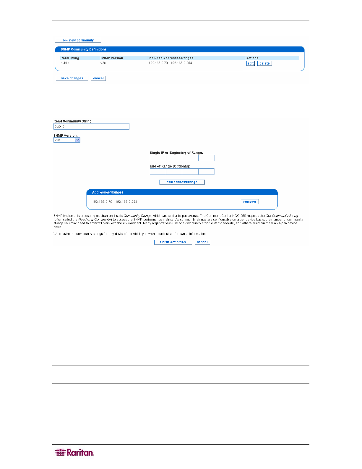
16 COMMANDCENTER NOC ADMINISTRATOR GUIDE
3. Click Edit the SNMP Ranges.
Figure 8 Edit SNMP Ranges
4. Click add new community or edit next to the already defined SNMP range.
Figure 9 Defining SNMP Ranges
5. Edit the community string or add a new one.
6. Specify the SNMP version by selecting v1, v2c, or Not Specified from the SNMP version
drop-down list box.
7. Add ranges or addresses to the community, one at a time. To enter a range, fill in both the
Single IP or Beginning of Range and End of Range fields, and click add address/range.
To enter a single address, simply leave off the End of Range address. Note that you must
provide an IP address or range for each string; if you wish to provide an SNMP string for all
devices that the CC-NOC is managing, just specify the range as 0.0.0.0 - 255.255.255.255.
Click remove if you wish to remove the defined addresses.
8. Click finish definition.
Note: Community Strings are required for any device from which you wish to collect SNMP
performance information. The default SNMP community string is public.
Configure Scheduled Outages
This page allows you to create reoccurring windows where services will not be polled on a
particular node. You can schedule planned outages for managed devices on your network. The
downtime experienced by a device during a scheduled outage will not count negatively against
the uptime statistics measured for the device.
1. Click on the Admin tab in the top navigation bar.
2. Click Network Management Configuration.

CHAPTER 2: GENERAL AND ADVANCED ADMINISTRATION 17
3. Click Configure Schedule Outages.
Figure 10 Configuring Scheduled Outages
4. Type a name for the scheduled outage and click add new scheduled outage.
5. Type a name for the scheduled outage.
6. Select a node label, that is, a DNS hostname or IP address, from the Included Node Label
drop-down list and click add. Adding a node label is optional and can be removed once
added.
7. Select an interface, that is, an IP address, from the Included Interfaces drop-down list and
click add. Adding an interface is optional and can be removed once added.
Figure 11 Edit Scheduled Outages
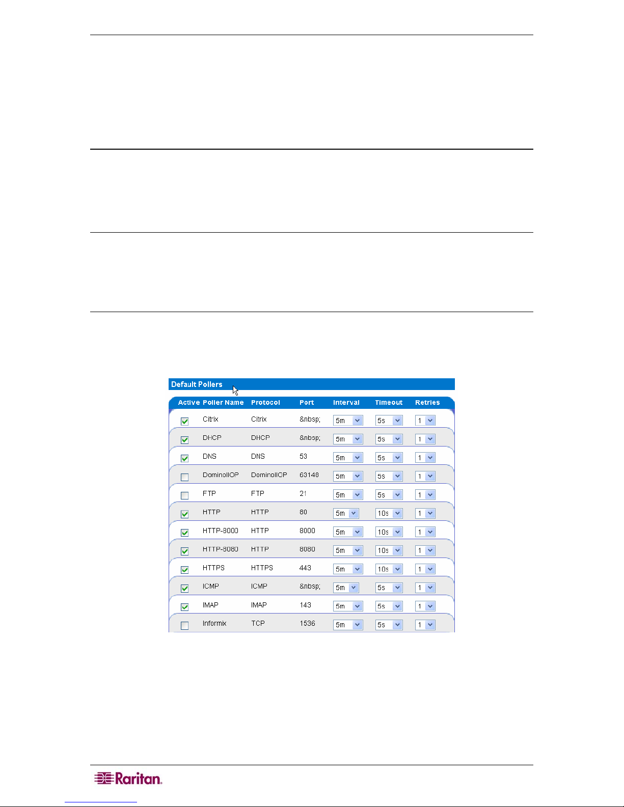
18 COMMANDCENTER NOC ADMINISTRATOR GUIDE
8. Specify an outage window. For outage windows that are set to Recurring Weekly, you cannot
specify outages that start on one day of the week and end on a different day. In these cases
where the outage spans 12:00 AM (Midnight), you should create two outages, one that ends
at 11:59 PM and another that begins at 12:00 AM on the following day. Even though there
appears to be a one minute gap between these outage spans, that is not the case. The outage
will be processed seamlessly.
9. Click add.
Configure Pollers
This page allows you to determine which of the default pollers, that is, the monitors that exercise
your web servers, email servers, etc. and create service down messages should be running on your
system. Also configurable is their behavior, for example, poll attempt timeouts, retry attempts, etc.
Additionally, you can create your own pollers for custom or niche applications you may be
running in your environment.
Note: The SNMP poller is disabled by default because in most cases, the availability of SNMP
data is not integral to the core business of a company, thus it is excluded from availability
calculations. Even if this poller is disabled, SNMP performance collection will still take place
and the SNMP graphs for statistics like network traffic and disk usage will be updated. If the
SNMP service experiences an outage, it may cause gaps in these graphs when data is unavailable
but the outage will not affect your availability statistics.
1. Click on the Admin tab in the top navigation bar.
2. Click Network Management Configuration.
3. Click Configure Pollers.
• The Active column shows the current status of the poller. If the active field is checked, the
poller will be scanned in the next poller rescan.
• The Poller Name column shows the name of each service in the poller configuration.
• The Protocol column shows the communications protocol used for polling each service.
• The Port column shows the ports at which the service will be polled.
• This panel also allows the admin user to configure polling intervals, the timeout period
between retries, and number of retries before an outage is declared. Adjusting polling
Figure 12 Configure Pollers
 Loading...