

Raritan MCC16R, MCC4R, MCC8RD, MCC16RD, MCC4 User Manual
...
UUsseerr’’ss MMaannuuaall
MCC4, MCC8, MCC16
MCC4R, MCC8R, MCC16R
MCC8RD, MCC16RD
Copyright © 1999
Raritan Computer, Inc.
Ver. 0C, AUG, 2000
UUsseerr’’ss MMaannuuaall
MCC4, MCC8, MCC16
MCC4R, MCC8R, MCC16R
MCC8RD, MCC16RD
Raritan CComputer, IInc.
400 Cottontail Lane
Somerset, NJ 08873
U.S.A.
Tel. 1-732-764-8886
Fax 1-732-764-8887
E-mail sales@raritan.com
http://www.raritan.com
Raritan CComputer EEurope, BB.V.
Eglantierbaan 16
2908 LV Capelle aan den IJssel
The Netherlands
Tel. 31-10-284-4053
Fax 31-10-284-4049
E-mail sales.europe@raritan.com
http://www.raritan.com
Raritan CComputer TTaiwan, IInc.
5F,121,Lane 235,Pao-Chiao Rd,
Hsin-Tien City,Taipei Hsien
Taiwan,ROC
Tel. 886-2-8919-1333
Fax 886-2-8919-1338
E-mail:sales.asia@raritan.com
http://www.raritan.com
Raritan CComputer JJapan, IInc.
Kuga Building 7F, 11-6
Kuramae 4-chome Taitoo-Ku
Tokyo 111-0051, Japan
Tel. 81-3-5833-6360
Fax 81-3-5833-6336
Email sales.japan@raritan.com
http://www.raritan.com

FCC Information
This equipment has been tested and found to comply with the limits for a Class
A digital device, pursuant to Part 15 of the FCC Rules. These limits are
designed to provide reasonable protection against harmful interference in a
commercial installation. This equipment generates, uses and can radiate radio
frequency energy and, if not installed and used in accordance with the instructions, may cause harmful interference to radio communications. Operation of
this equipment in a residential environment may cause harmful interference.
Product names mentioned in this document are trademarks or registered trademarks of their respective companies. MasterConsole
MX
4
, MasterConsole, and
their respective logos are registered trademarks of Raritan Computer, Inc. PS/2,
RS/6000, and PC/AT are registered trademarks of the International Business
Machines Corporation. Mac is a registered trademark of Apple Computer, Inc.
Sun is a registered trademark of Sun Microsystems. Alpha is a registered trademark of Digital Equipment Corporation. HP9000 is a registered trademark of
Hewlett Packard. SGI is a registered trademark of Silicon Graphics, Inc.
Japanese Approvals

Table of Contents
FCC INFORMATION I
T
ABLE OF CONTENTS II
T
ABLE OF FIGURES III
WELCOME
1
OVERVIEW 1
FEATURES 1
ONE-TIER AND TWO-TIER CONFIGURATIONS 2
GETTING STARTED 3
ONE-TIER CONFIGURA
TION 4
INSTALLING MASTERCONSOLE II (ONE-TIER) 4
CONFIGURING MASTERCONSOLE II (ONE-TIER) 6
ASSIGNING NAMES AND SCAN RATES (ONE-TIER) 8
USING MASTERCONSOLE II SECURITY FEATURE (ONE-TIER) 10
Passwords 10
Turning Security on/off and Changing Passwords: 10
OPERATING MASTERCONSOLE II
USING ON-SCREEN USER INTERFACE (ONE-TIER) 12
Selecting a Computer 12
Setting AutoScan 14
OPERATING MASTERCONSOLE II
USING FRONT PANEL BUTTONS (ONE-TIER) 14

TWO-TIER CONFIGURATION 16
INSTALLING MASTERCONSOLE II (TWO-TIER) 16
Install Base Unit (First-Tier) MasterConsole II 16
Connect Second-Tier MasterConsole(s) to the Base Unit 17
Connect Computers to Second-Tier MasterConsole(s) 18
CONFIGURING THE BASE MASTERCONSOLE II (TWO-TIER) 19
ASSIGNING NAMES AND SCAN RATES (TWO-TIER) 21
USING THE MASTERCONSOLE II SECURITY FEATURES (TWO-TIER) 23
OPERATING MASTERCONSOLE II (TWO-TIER) 23
Selecting a Computer 23
REMOTE
ACCESS USING CAT5 REACH 27
APPENDICES
28
SYSTEM DEFAULT SETTINGS 28
ON-SCREEN USER INTERFACE FUNCTION KEYS 29
MASTERCONSOLE CONFIGURATIONS AND
PROGRAMMING MASTERCONSOLE II AT POWER UP 30
MasterConsole II product Design Background and Considerations 30
Programming MasterConsole II 30
MASTERCONSOLE II CONFIGURATION DIAGRAMS 31
GLOSSARY 34
TROUBLESHOOTING 38
SPECIFICATIONS 41
Main Unit 41
Universal Cable Kits 42
Accessories 42
Remote Access Kit 42

TABLE OF FIGURES
FIGURE 1. ONE-TIER CONFIGURATION 2
FIGURE 2. TWO-TIER CONFIGURATION (WITH OPTIONAL REMOTE ACCESS) 2
FIGURE 3. MASTERCONSOLE II BACK PANEL 4
FIGURE 4. ONE-TIER CONFIGURATION CABLING DETAILS 5
FIGURE 5. CABLE ADAPTERS TO CONVERT PS/2 TO AT 5
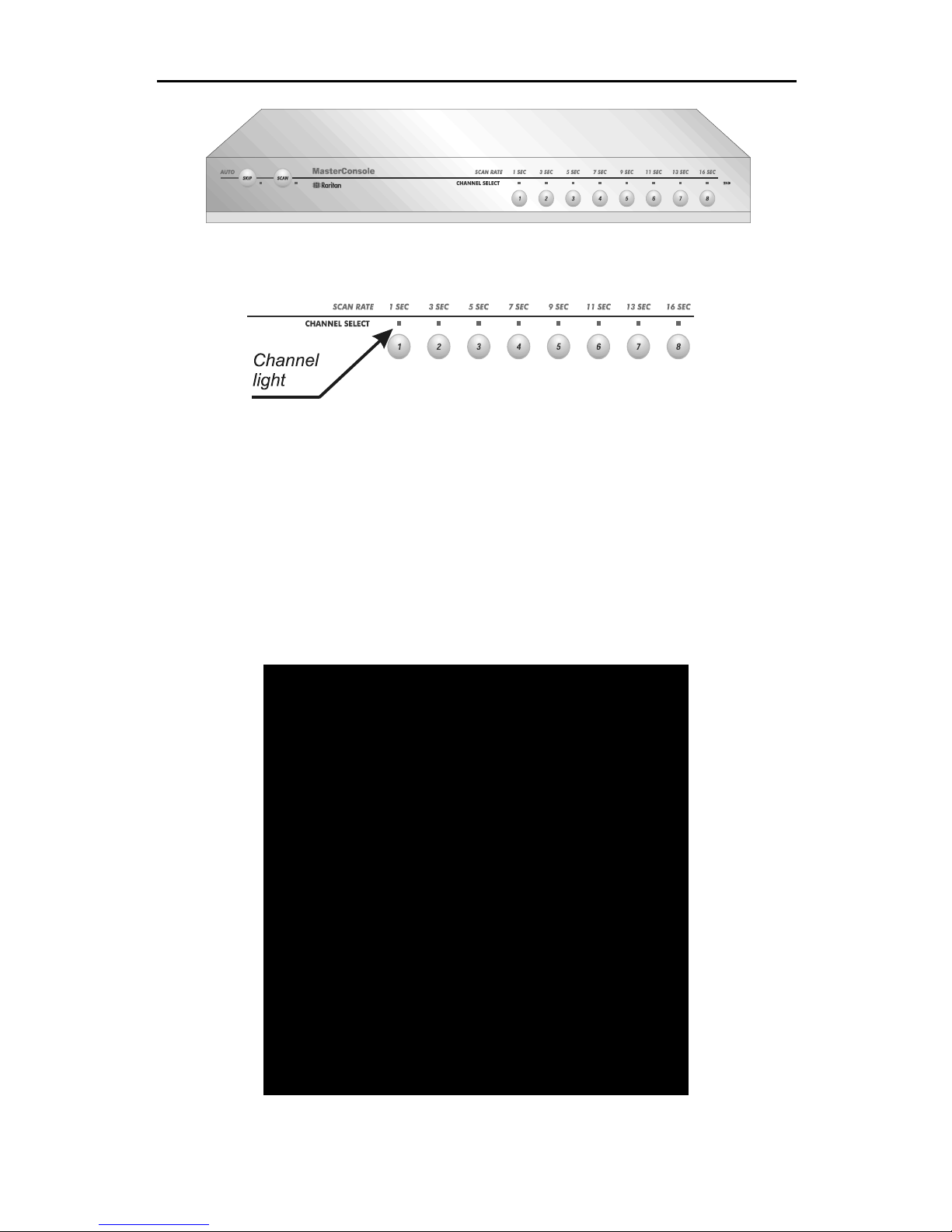
FIGURE 6. MASTERCONSOLE II FRONT PANEL 6
FIGURE 7. MASTERCONSOLE II FRONT PANEL (CHANNEL LIGHTS) 6
FIGURE 8. CONFIGURATION MENU 6
FIGURE 9. EDIT NAMES AND SCAN RATE MENU (ONE-TIER) 9
FIGURE 10. ADMINISTRATION MENU 11
FIGURE 11. SELECTION MENU (ONE-TIER, SORTED BY CHANNEL ID) 12
FIGURE 12. TWO-TIER CONFIGURATION (WITH OPTIONAL REMOTE ACCESS KIT) 16
FIGURE 13. TWO-TIER CONFIGURATION CABLING DETAILS 17
FIGURE 14. CONFIGURATION MENU (TWO-TIER) 19
FIGURE 15. DEVICE TYPES 20
FIGURE 16. DEVICE FIELD 20
FIGURE 17. DEFAULT MASTERCONSOLE II CHANNEL IDS AND NAMES 21
FIGURE 18. EDIT NAMES AND SCAN RATE MENU (BASE MASTERCONSOLE II) 22
FIGURE 19. EDIT NAMES AND SCAN RATE MENU (SECOND-TIER MCC8) 23
FIGURE 20. SELECTION MENU (TWO-TIER, BASE MASTERCONSOLE II) 25
FIGURE 21. SELECTION MENU (TWO-TIER, SECOND TIER) 26
FIGURE 22. REMOTE ACCESS WITH CAT5 REACH 27
FIGURE 23. TWO-TIER CONFIGURATION WITH SATELLITE UNIT 27
FIGURE 24. BASIC ONE-TIER CONFIGURATIONS 31
FIGURE 25. ONE-TIER WITH REMOTE ACCESS KIT 31
FIGURE 26. TWO-TIER CONFIGURATION OF UP TO 256 COMPUTERS 32
FIGURE 27. TWO-TIER CONFIGURATION WITH MASTERCONSOLE P MODEL 32
FIGURE 28. TWO-TIER CONFIGURATION WITH SATELLITE UNIT 33

Welcome
Overview
Raritan's keyboard/video/mouse (KVM) switches are engineered to provide reliable, cost-effective, central control of multiple computers. This
eliminates the cost and clutter of unnecessary equipment, reclaims
space, and improves productivity for a host of applications.
MasterConsole II enables control of any mix of 2 to 256 computers
from a single keyboard, monitor, and mouse. MasterConsole II user
interface provides simple on-screen control and system management.
Raritan's unique emulation technology dedicates a keyboard/mouse
emulator for each computer to ensure that each computer always 'sees'
its own keyboard and mouse. This means smooth, flawless switching
and operation, even when computers are running the most demanding
operating systems.
Features
· Models for 4, 8, or 16 computers
· Mix any brand PCs, Macs, Suns, Alphas, RS/6000s, HP9000s, SGIs
· “Keep-alive” emulation ensures non-stop computer operation in the
event of power loss to the switch
· High resolution video-1600x1280
· Tangle-proof, double-shielded coaxial cable from 6.5, to 30 feet
· On-screen user interface for simple control and system management
· Assign meaningful names to computers for quick identification and
selection
· Operate with front panel buttons or hot-keys with on-screen menus
· AutoSkip function to bypass inactive channels
· AutoScan computers at variable rates
· Password Security to ensure authorized access to computers
· Optional Dual Remote access capability with Cat5 Reach
· Compatible with MasterView ready MasterConsole P Models (MCPn)
· Cascade from a multi-user MasterConsole MX
4
· One year warranty for parts and labor
1
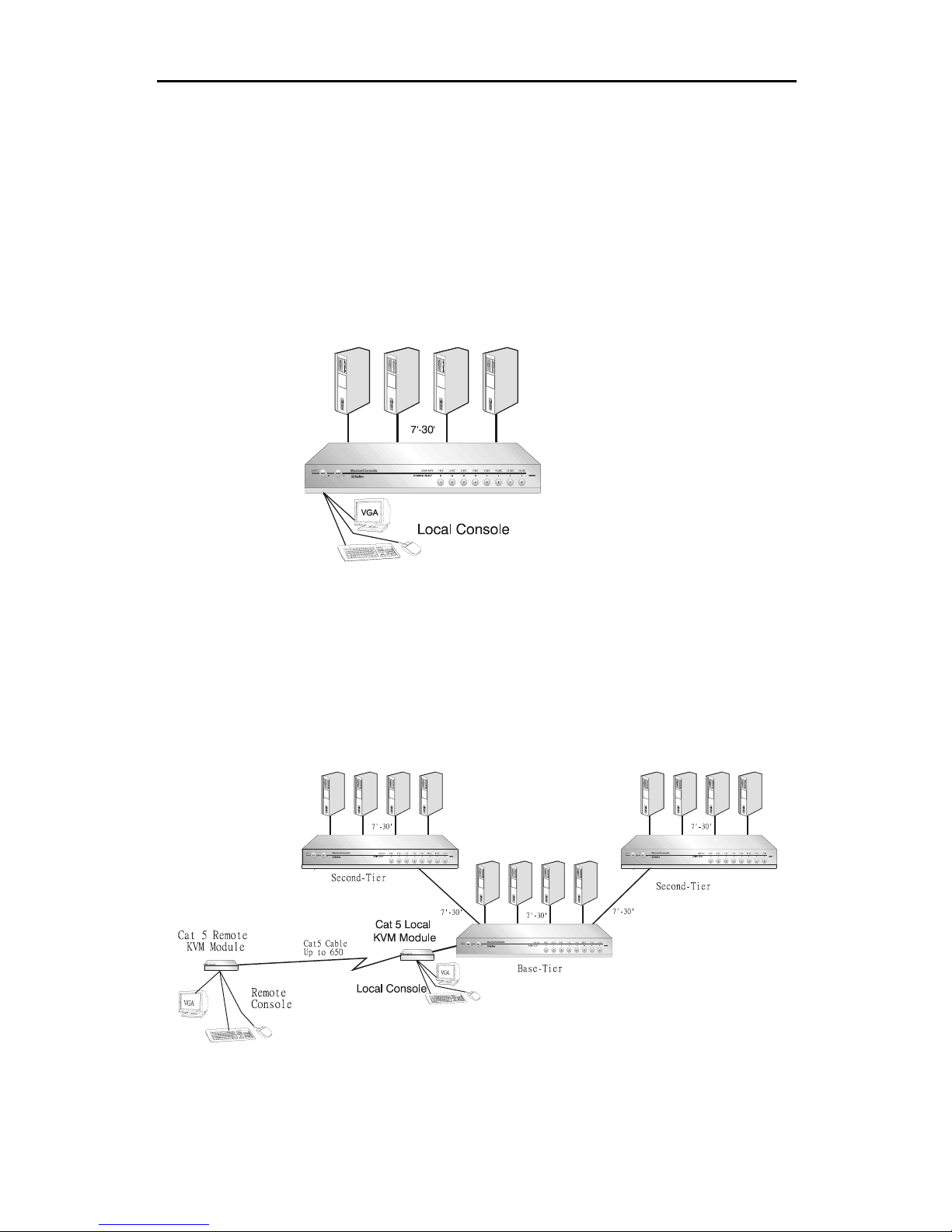
One-Tier and Two-Tier Configurations
MasterConsole II can be configured in one or two tiers, depending on the
number of computers you want to control. In a one-tier configuration,
only computers are connected to a single MasterConsole II unit. See
Figure 1. In a two-tier configuration, either a computer or another
MasterConsole unit is connected to each channel of the base
MasterConsole II unit. See Figure 2.
2
Figure 1. One-Tier Configuration
Figure 2. Two-Tier Configuration (With optional Remote Access)

Getting Started
MasterConsole II is designed for quick, easy installation and operation.
Follow the steps for either one-tier or two-tier configuration to be up and
running within minutes:
1. Install MasterConsole II (connect computers).
2. Configure MasterConsole II.
3. Assign computer names and set channel-specific Scan
Rates for attached computers.
4. Turn ON security and change passwords if you want to
restrict access to computers connected to MasterConsole II.
5. Operate using On-Screen User Interface or front panel buttons.
6. Install optional Cat5 Reach for remote console or satellite unit.
3
Quick-Start Operation
After you connect computers to your MasterConsole II
you may wish to explore MasterConsole II operation
with the default names and parameters.
You may operate using the front panel buttons and/or
the On-Screen User Interface. To activate On-Screen
User Interface, press the <ScrollLock>> key twice
rapidly. The Selection Menu will appear. To select a
computer, use the <Ï>/<Ð> keys to highlight the
desired channel (computer) and press <Enter>or
press the desired computer's Key number (located in
the left-hand column). To select another computer,
use front panel buttons or re-activate the On-Screen
User Interface.
One-Tier Configuration
Installing MasterConsole II (One-Tier)
1. Shut down and power off all computers to be connected to
MasterConsole II.
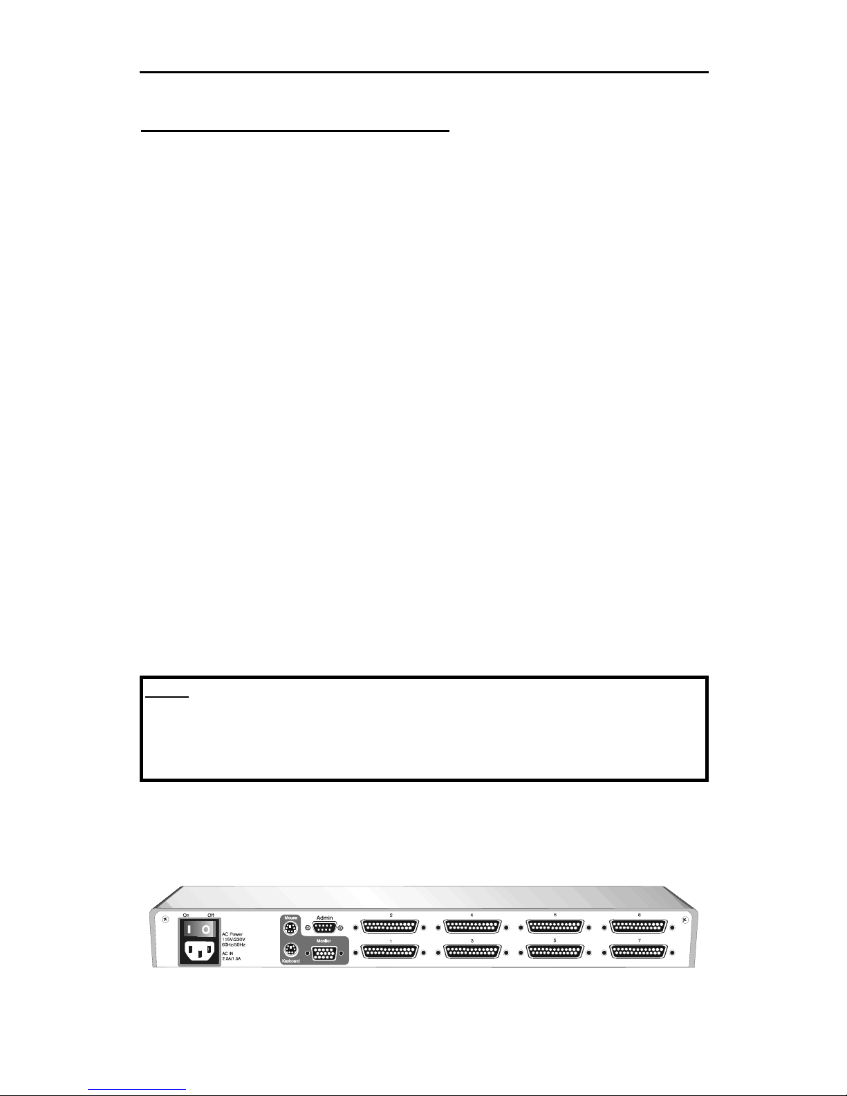
2. Plug a keyboard, monitor, and mouse into the keyboard, moni-
tor, and mouse ports on the MasterConsole II back panel. See
Figure 3 and Figure 4.
3. Power ON the MasterConsole II unit.
4. Using a universal cable kit (CCPnnU), plug the 25-pin connector
into one of the numbered channels on the MasterConsole II back
panel.
5. Plug the cable's other connectors into the computer's keyboard,
monitor, and mouse ports. Use supplied adapters for AT style
PCs. See Figure 5.
6. Power ON the connected computer.
7. Select the connected computer by pressing the corresponding
front panel button. Verify that the monitor attached to
MasterConsole II displays the video for the connected computer.
Use the keyboard and mouse attached to MasterConsole II to
verify that they operate the connected computer.
8. Repeat Steps 4 through 7 to connect the remaining computers to
MasterConsole II.
4
Figure 3. MasterConsole II Back Panel
Note: An amber channel light above a numbered channel button on
the MasterConsole II front panel indicates that the channel is
active; that is, a computer is connected and powered on. A
green light above a numbered channel button indicates the cur
rently displayed channel. See Figure 6 and Figure 7.

5
Figure 5. Cable Adapters to convert PS/2 to AT
Figure 4. One-Tier Configuration Cabling Details
Configuring MasterConsole II (One-Tier)
The Configuration Menu is used to specify your MasterConsole II configuration and to set/change operation parameters.
1. Activate On-Screen User Interface by pressing the hot-key
(<ScrollLock> by default) twice rapidly.
6
Figure 6. MasterConsole II Front Panel
Figure 7. MasterConsole II Front Panel (Channel lights)
Configuration Menu
Connected: 01 PC0001
Model: MCC8 Name: MCC8
Device: . . . . . . . .
Scan: Off Set: 15 Seconds
Mode: Global
Skip: On
ID Display: 20 Seconds
Hot Key: Scroll Lock
Display Position: Menu ID
Green Mode: Off 15 Minutes
Previous Channel Key: CapLck
F1 F2 F3 F4 F5 F6 F7 Esc
Figure 8. Configuration Menu

2. Press <F4> to access the Configuration Menu. See Figure 8.
· The Connected field displays the Channel ID and Name of the
currently selected computer.
· The Model field displays the model number of this
MasterConsole unit.
3. Use the <Tab> (forward)/<Shift-Tab> (backward) keys to
highlight the desired field and make your changes as follows:
· To change Name (default is the unit’s model number): Move to
Name and type a name up to five characters. This field is used
for your identification purposes only.
· The Device field specifies the type of device connected to each
channel. The default character is ".", which indicates that the
device is a computer. In a one-tier configuration, only a computer may be connected to each channel. The Device field settings
may be changed when expanding to a two-tier configuration.
See Figure 15, page 19 for two-tier device type settings.
· To turn AutoScan ON/OFF (default is OFF): Move to Scan and
press the <
Ï>/<Ð> keys to toggle. If you exit On-Screen User
Interface with AutoScan ON, MasterConsole II will scan according
to the currently set mode (Individual/Global) and scan rate.
a. a. To change the Global Scan Rate (default is 3 sec-
onds): Move to Set and type a number from 01 to 99,
or press the <Ï>/<Ð> keys to specify the Scan Rate
(in seconds) for Global AutoScan.
b. To change AutoScan mode (default setting is
Global): Move to Mode and press the <Ï>/<Ð> keys
to toggle between Global and Individual. See page
34 for description.
· To turn AutoSkip ON/OFF (default is OFF): Move to Skip and
press the <
Ï>/<Ð> keys to toggle. With AutoSkip ON, only
active channels can be selected.
· To change the ID Display time interval (default is 3 seconds):
Move to ID Display and type a number from 01 to 99, or press
the <
Ï>/<Ð> keys to specify the interval (in seconds) you want
the Channel ID and Name to display when each computer is
selected. Type 99 if you want the Channel ID and Name to display continuously.
· To change the On-Screen User Interface activator (default is
<Scroll Lock>): Move to Hot Key and press the <Ï>/<Ð> keys
to select the desired key. The hot-key can only be
<ScrollLock> <NumLock>, <CapsLock>, left <Shift> or left
7

<Alt>.
· To change the Menu Display position: Move to Menu and
press <Enter>. Then press the <Ï>, <Ð>, <Í>, and <Î> keys
to move the menu vertically and horizontally to the desired
position. Then press <Esc> or <Enter>.
· To change the Channel ID display position: Move to ID and
press <Enter>. Then press the <
Ï>, <Ð>, <Í>, and <Î> keys
to move the menu vertically and horizontally to the desired
position. Then press <Esc> or <Enter>.
· To turn PowerSave ON/OFF (default is OFF): Move to Green
Mode and press the <Ï>/<Ð> keys to toggle. To change the
PowerSave delay time (default is 15 minutes): Move to the
next field and type a number from 01 to 99, or press the
<
Ï>/<Ð> keys to change the interval (in minutes) of inactivity
(no keyboard or mouse operation) after which the video signal
will be cut off from the monitor. This will allow a properly
equipped monitor to enter low-energy mode.
· To select Previous Channel Toggle (default is CapsLock).
This feature enables the user to toggle between the previous
and current selected channel. Press F4 to display the
Configuration menu (Figure 1) and move the cursor to the
Previous Channel Key. Use the <-> or <¯> keys to select the
key, <caps lock>, <scroll lock>, <num lock>, left <shift>, or left
<alt> to be used. This feature enables the user to switch back
to a previous channel by pressing the selected key twice rapidly. There is no need to activate the OSUI.
NOTE: Select a previous channel key that is not being used as
the current hot key activator.
4. To exit the Configuration Menu: Press an appropriate Menu F
key to go to another menu, or press <Esc> to exit On-Screen
User Interface and return to normal computer operation. Any
changes made to the Configuration Menu are automatically
saved.
Assigning Names and Scan Rates (One-Tier)
You may assign meaningful names to quickly and easily identify and
select connected computers. By default, the channel name is PC00aa
(where aa is the channel ID number) and the Channel-Specific Scan
Rate is 3 seconds.
1. Activate On-Screen User Interface.
8
2. Press <F3> to access the Edit Names and Scan Rate Menu.
See Figure 9.
3. Use the <Tab>, <Shift-Tab> or <
Ï>/<Ð> keys to move the
cursor to the line you want to edit. Use <
Í>/<Î> to move
within a line.
· To change the Name: Type up to 8 characters (no spaces).
· To change the Channel-Specific Scan Rate (default is 3 sec-
onds): Type a number from 00 to 99 (seconds). When the
AutoScan Mode in the Configuration Menu is set to Individual,
these Channel-Specific Scan Rates are enabled. If the
AutoScan mode is set to Global, the global value will be used.
4. When you move to a different page or exit this Menu, you are
prompted to save your changes. Press <Y> to save.
5. To exit the Edit Names and Scan Rate Menu: Press any
Menu F key to go to another menu, or press <Esc> to go to the
Selection Menu.
9
Edit Names and Scan Rate
MC: MCC8 Page: 1 / 1
Ch. ID Name Scan Rate
............ ................. ....................
01 PC0001 05
02 Sara 03
03 Sales-2 10
04 Bob 04
05 PC0005 06
06 PC0006 08
07 Market-4 03
08 JoePC 02
............ ................. ....................
F1 F2 F3 F4 F5 F6 F7 Esc
Figure 9. Edit Names and Scan Rate Menu (One-Tier)
Note: If your MasterConsole II is a 16-channel model, MCC16, use the
<Page Up>/<Page Down> keys to view the next or previous
group of eight channels.
 Loading...