

Page 1
QUICK SETUP GUIDE
MasterConsole Digital®
Thank you for purchasing the MasterConsole Digital (MCD) KVM switch or MCD-LED KVM combination switch and
drawer. MCD is the most user-friendly 1U KVM switch for accessing 8 to 32 servers, and MCD-LED is a 1U KVM
combination switch and drawer for accessing 8 to 16 servers.
Four MCD models are available: MCD-108/116 for one-user operation, and MCD-216/232 for dual-user operation. If
establishing a
two-tier
Two MCD-LED models are available: MCD-LED17108 and MCD-LED17116 for one-user operation.
MCD system, you can even access a maximum of 1024 servers.
This Quick Setup Guide explains how to quickly install and use either product. For further details on using this product,
access its Online Help or User Guide on the
Support page (http://www.raritan.com/support/
Package Contents
The MCD or MCD-LED comes with standard parts shown
below. If anything is missing or damaged, contact Raritan
Technical Support or the local vendor immediately.
MCD KVM switch or MCD-LED KVM drawer x 1
Power cord x 1
Rackmount kit x 1 (including brackets and associated
screws)
DVI-I to VGA adapter x 1
Note: This adapter can be used for connecting a VGA
monitor or for connecting a 2nd-tier MCD switch via
"MDUTP". For details, see
Keyboard/Mouse/Monitor
Two-Tier System
(on page 6).
Step B: Connect the
(on page 4) or
Establishing a
Quick Setup Guide x 1
Warranty card x 1
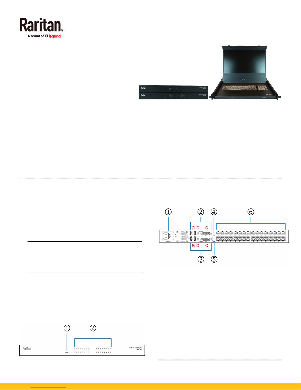
MCD Structure Diagrams
The following diagrams illustrate the dual-user model
MCD-232.
Front View
1. Power LED
2. Channel LEDs
Rear View
1. Power socket and power switch
2. 'Console 2' connectors (available on dual-user models
only):
a. Two USB-A ports
b. One audio output
c. One DVI-I connector
3. 'Console 1' connectors:
a. Two USB-A ports
b. One audio output
c. One DVI-I connector
4. Reset button
5. Firmware upgrade connector
6. Channel ports
QS Rule
).
MasterConsole Digital QSG 1
QSG-MCD-0A-v1.0.0-E 255-20-0008-00 RoHS
Page 2

MCD Rackmount Procedure
MCD switches can be mounted in 1U (1.75", 4.4cm) of vertical
space in a standard 19" equipment rack. To rack-mount it,
use the brackets and screws that come with the device.
Step 1: Attach the Cable-Support Bar
You can install the cable-support bar onto the rackmount
brackets to bear all cables connected to the MCD switch. The
proper position to attach this bar depends on the switch's
front panel position in the rack.
If the front panel will face the front of the rack, fasten the
bar to the L-shaped holes
rackmount brackets.
If the front panel will face the rear of the rack, fasten the
bar to the L-shaped holes
rackmount brackets.
far from
close to
the ears of the
the ears of the
2. Align two little holes of the bracket with two threaded
holes on one side of the MCD.
3. Secure the bracket to the MCD with two of the included
screws.
To attach the cable-support bar:
1. Insert either end of the cable-support bar into one of the
L-shaped holes on a rackmount bracket.
2. Align the bar's threaded hole with the threaded hole at the
end of the rackmount bracket. Then secure the bar with
one of the included cap screws.
3. Repeat the above steps for attaching the other bracket.
4. Repeat the same steps for attaching the other bracket.
5. Mount the MCD in the rack by securing the brackets' ears
to the rack's front rails with your own fasteners.
QS Rule
MCD-LED Structure Diagrams
The following diagrams illustrate MCD-LED17116.
Front View
Step 2: Rack Mount the MCD
When rack-mounting the MCD switch, you can let it face
either the front or the rear of the rack to meet your needs.
To rack-mount the MCD:
1. Slide the MCD between the two rackmount brackets.
MasterConsole Digital QSG 2
QSG-MCD-0A-v1.0.0-E 255-20-0008-00 RoHS
1. Touchpad and keyboard
2. USB port for connecting a USB HID-compliant
keyboard/mouse -- wired or wireless
Page 3
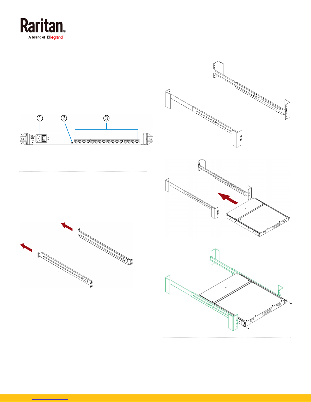
Note: This USB port does not support a USB storage
drive.
3. Indicators for Num Lock, Caps Lock and Scroll Lock
4. TFT LCD display
5. Locking latches
6. OSD buttons, power button and indicator lamp
7. Adjustable mounting brackets
Rear View
1. Power socket and power switch
2. Firmware upgrade connector
3. Channel ports
QS Rule
MCD-LED Rackmount Procedure
MCD-LED KVM drawers can be mounted in 1U (1.75", 4.4cm)
of vertical space in a standard 19" equipment rack. To
rack-mount it, use the brackets and screws that come with
the device.
1. Adjust the length of both brackets to match the mounting
depth of your rack.
2. Fasten the brackets to the rack rails securely with your
own fasteners.
3. Slide the MCD-LED between the brackets.
4. Fasten the MCD-LED to the rack.
QS Rule
Basic Installation
For MCD, follow steps A, B, and C. For MCD-LED, follow steps
A and C.
MasterConsole Digital QSG 3
QSG-MCD-0A-v1.0.0-E 255-20-0008-00 RoHS
Page 4
Step A: Select Proper MDCIMs or MDUTPs
Choose appropriate MDCIMs or MDUTP cables according to
the server's video port and your audio requirements.
MCD CIM type Video type Audio transmission
MDUTP cables VGA Support analog audio
MDCIM-DVI
MDCIM-HDMI
MDCIM-DP
DVI NO support
HDMI Support digital audio
Display Port NO support
Tip: If any MDCIM or MDUTP cable you purchase is not
compatible with the video port on your server, the alternative
solution is to connect a video converter or adapter to MDCIM
or MDUTP.
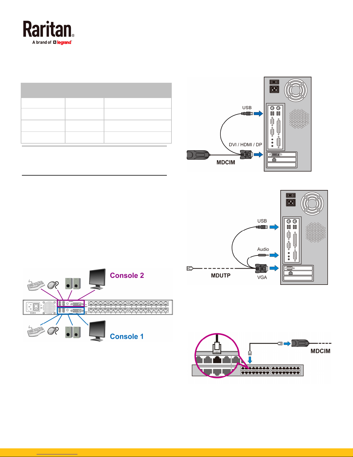
Step B: Connect the Keyboard/Mouse/Monitor
1. Turn OFF all devices, including the MCD switch and
servers.
2. Connect a keyboard, mouse and monitor to the 'Console'
connectors on the MCD.
If using a VGA monitor, a DVI-I to VGA adapter is
required.
The headphone or speakers are optional.
If your MCD is a dual-user model, you can connect an
additional keyboard, mouse and monitor to the other
'Console' connectors.
Make sure the MDCIM's or MDUTP's video type
matches your server's. See
MDCIMs or MDUTPs
Step A: Select Proper
(on page 4).
c. Optionally, plug the MDUTP's audio connector into the
server's audio output port.
2. Connect the server to the MCD switch. The distance can be
up to 45 meters (147.6 feet).
MDCIM:
Use a standard network patch cable (Cat5e/6
UTP) to connect the MDCIM attached with the server to
the MCD channel ports.
Step C: Connect Servers
1. Connect one MDCIM or MDUTP cable to the server.
a. Plug the MDCIM or MDUTP's USB connector into one
of the server's USB ports.
b. Plug the MDCIM or MDUTP's video connector into the
server's video port.
MasterConsole Digital QSG 4
QSG-MCD-0A-v1.0.0-E 255-20-0008-00 RoHS
MDUTP cable:
Simply plug the other end of the MDUTP
cable into any channel port.
3. Repeat the above steps to connect more servers.
4. Power on all devices.
Page 5
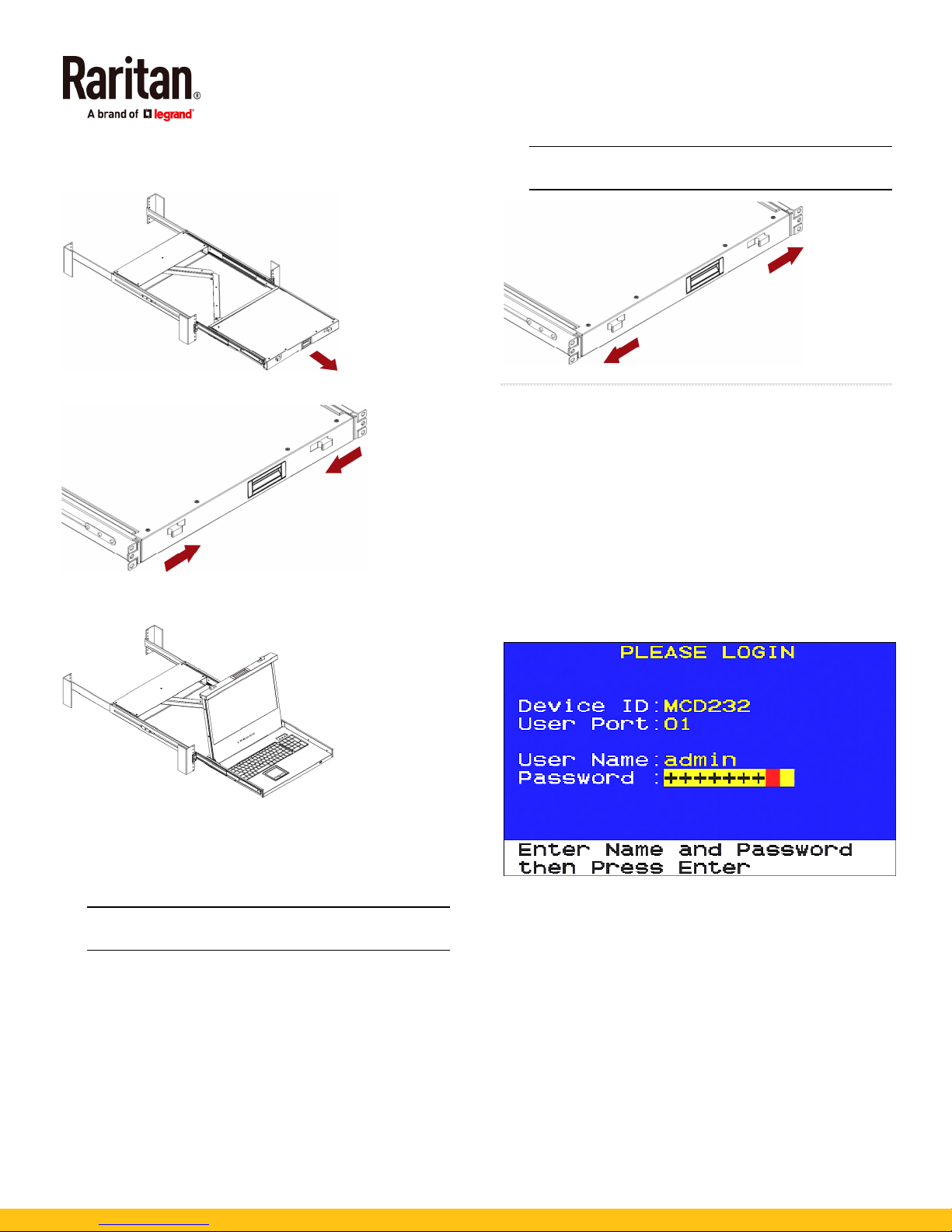
Using the MCD-LED
1. Pull out the MCD-LED.
2. Push the locking latches toward the center.
3. Flip up the LCD display, and press the power button on the
LCD display.
Warning: When closing the MCD-LED, keep your fingers
clear of it.
QS Rule
OSD Operation
MCD and MCD-LED share the same OSD operations.
Login
After turning on the device, the login screen displays. For
initial login, use the built-in administrator account.
To log in:
1. Type the default user credentials and press Enter. User
credentials are case sensitive.
User Name: admin
Default Password: raritan
4. To fine tune the video quality after accessing a server, do
either below:
Press the UP/AUTO button on the LCD display.
Press MENU, make sure Auto Adjust has been
selected, and press MENU to confirm.
Note: For instructions on accessing a server, see
Accessing a Server
(on page 6).
2. The Selection Menu displays, indicating the login is
successful.
5. To close and lock the LCD display, push the locking
latches toward the edges.
MasterConsole Digital QSG 5
QSG-MCD-0A-v1.0.0-E 255-20-0008-00 RoHS
Page 6
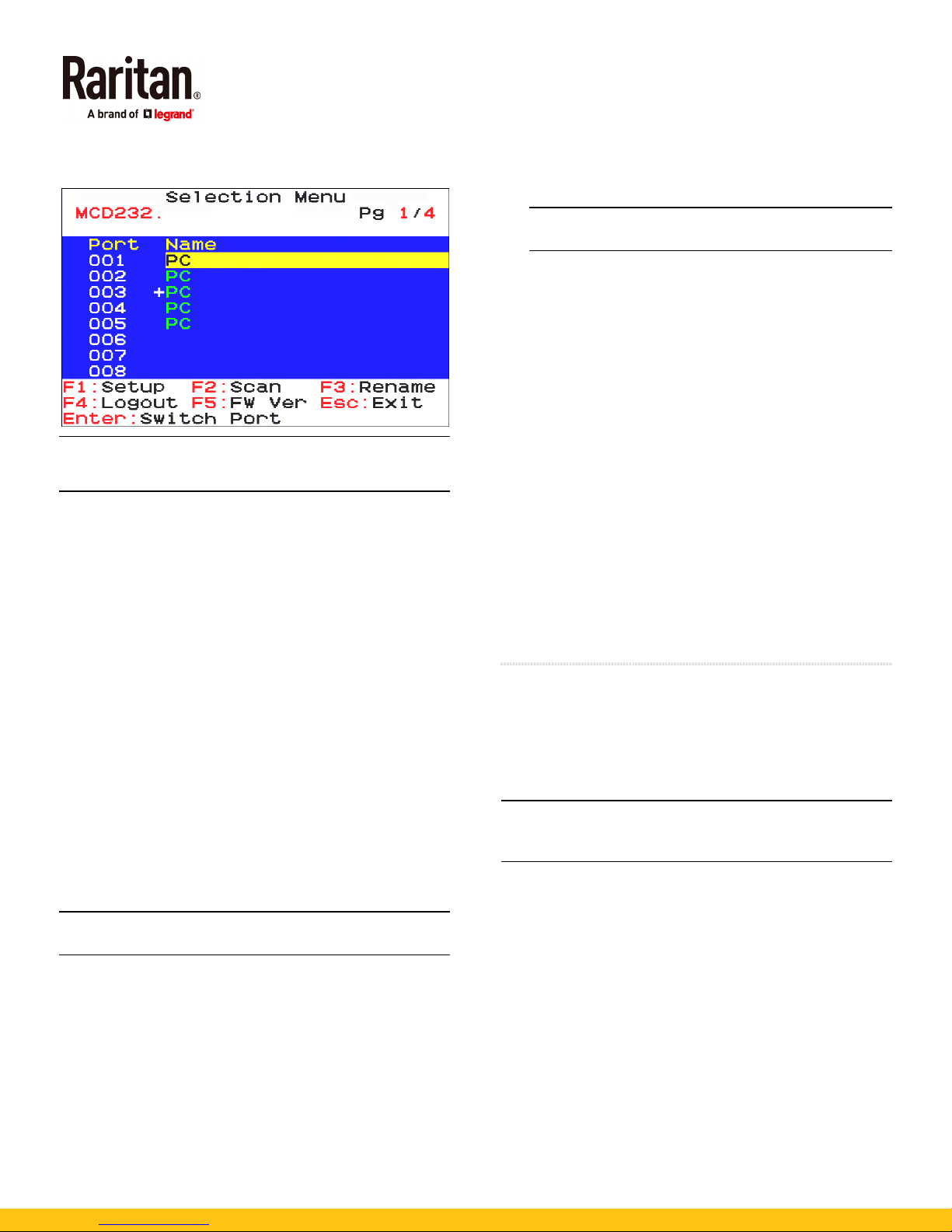
To select a channel, see
Menu
(on page 6).
Using the Channel Selection
Important: It is strongly recommended to change the
default password for the security of your MCD system. For
details, refer to "User Management" in the User Guide.
Accessing a Server
After login, you can select any channel to view and/or control
the connected server. There are two methods for channel
selection.
Selection Menu of the On-Screen Display (OSD)
Hot keys
Using the Channel Selection Menu
You must use the OSD hot key to trigger the OSD. The default
hot key is 'Scroll Lock.'
To select a channel via the Selection Menu:
1. Press 'Scroll Lock' 3 times. The Selection Menu appears,
showing a list of channels.
2. If the desired channel is not shown on the current page,
press Page Down or Page Up.
3. Press or to select one of the "active" channels, and
press Enter.
Channels with channel names displayed are "active"
channels. The default name is 'PC'.
Note: To return to the 1st-tier Selection Menu, press the
letter 'R' while the 2nd-tier Selection Menu is being displayed.
Using Hot Keys
You can switch between channels without triggering the OSD.
To access any channel, using hot keys:
1. Make sure there is no OSD shown onscreen. If yes, press
Esc to exit.
2. To select any channel, press 'Scroll Lock' twice, then the
channel number, and press Enter.
For example, to access channel 15, press the following
keys.
Scroll Lock > Scroll Lock > 15 > Enter
Important: If you do not press Enter, no channel
switching occurs.
3. The video of the accessed server displays onscreen. Now
you can control the server with the keyboard and mouse.
To access the next or prior "active" channel, using hot
keys:
1. Make sure there is no OSD shown onscreen.
2. To select the next "active" channel, press the RIGHT 'Ctrl'
key twice.
3. To select the prior "active" channel, press the LEFT 'Ctrl'
key twice.
Logout
After completing your tasks, you should log out to prevent
unauthorized people from accessing the MCD system.
To log out of the MCD system:
1. If the OSD is not displayed onscreen, press 'Scroll Lock' 3
times.
2. Press F4.
3. The Login screen appears, indicating that you have
successfully logged out.
QS Rule
Establishing a Two-Tier System
To increase the total number of servers a user can access,
establish a two-tier system.
In the two-tier system, the 1st tier comprises only one MCD
switch, which is called 'base switch' in the following context.
The 2nd tier comprises 1 to 32 additional MCD switches.
Tip: You can also use one MCD-LED KVM drawer as the base
switch, but this product cannot be a 2nd-tier KVM switch
because it does not have a console port.
STEP (a): Connect the 2nd-tier switch(es) to the base
switch
STEP (b): Connect the keyboard, mouse, monitor and
audio devices to the base switch
STEP (c): Connect servers to the two-tier system
Step (a): Connect 2nd-Tier Switches to the Base
Switch
You can mix identical or different MCD models in a two-tier
system. For example, you may connect a MCD-116 switch to a
MCD-232 base switch.
To cascade MCD switches:
1. Turn OFF all MCD switches, including the base switch.
MasterConsole Digital QSG 6
QSG-MCD-0A-v1.0.0-E 255-20-0008-00 RoHS
Page 7
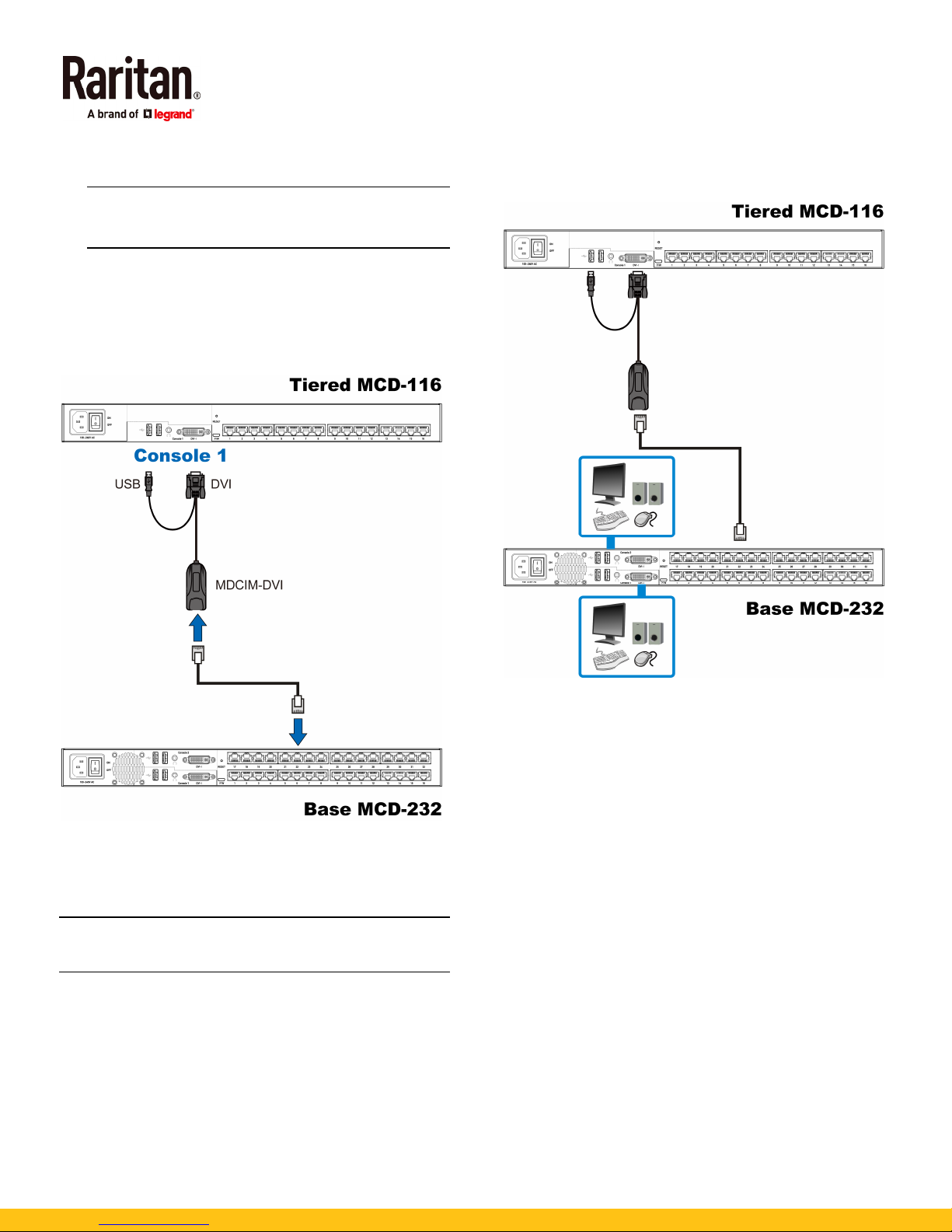
2. Connect the 2nd-tier MCD switch to the base switch via
one MDCIM-DVI.
Note: If support for audio transmission with the 2nd-tier
switch is required, you must use the MDUTP cable and a
Raritan's DVI-I to VGA adapter to connect the 2nd tier.
a. Plug the connectors of the MDCIM or MDUTP into the
'Console 1' connectors of the 2nd-tier switch. You
CANNOT connect them to 'Console 2'.
b. Use a standard network patch cable (Cat5e/6 UTP) to
connect the 2nd-tier MDCIM to any channel port of the
base switch.
For details on connecting keyboards, mice, monitors and
optional audio input devices, see
Keyboard/Mouse/Monitor
Step B: Connect the
(on page 4).
3. Repeat the above step to connect more 2nd-tier switches
to the base switch.
4. Turn on all "2nd-tier" switches.
5. Turn on the base switch.
Important: Turn on 2nd-tier switches prior to the base
switch so that the base switch downloads up-to-date
channel data from the 2nd tier.
Step (b): Connect Keyboards, Mice, Monitors and
Audio Devices
You must connect one or two sets of keyboards, mice and
monitors to the base switch.
MasterConsole Digital QSG 7
QSG-MCD-0A-v1.0.0-E 255-20-0008-00 RoHS
Page 8
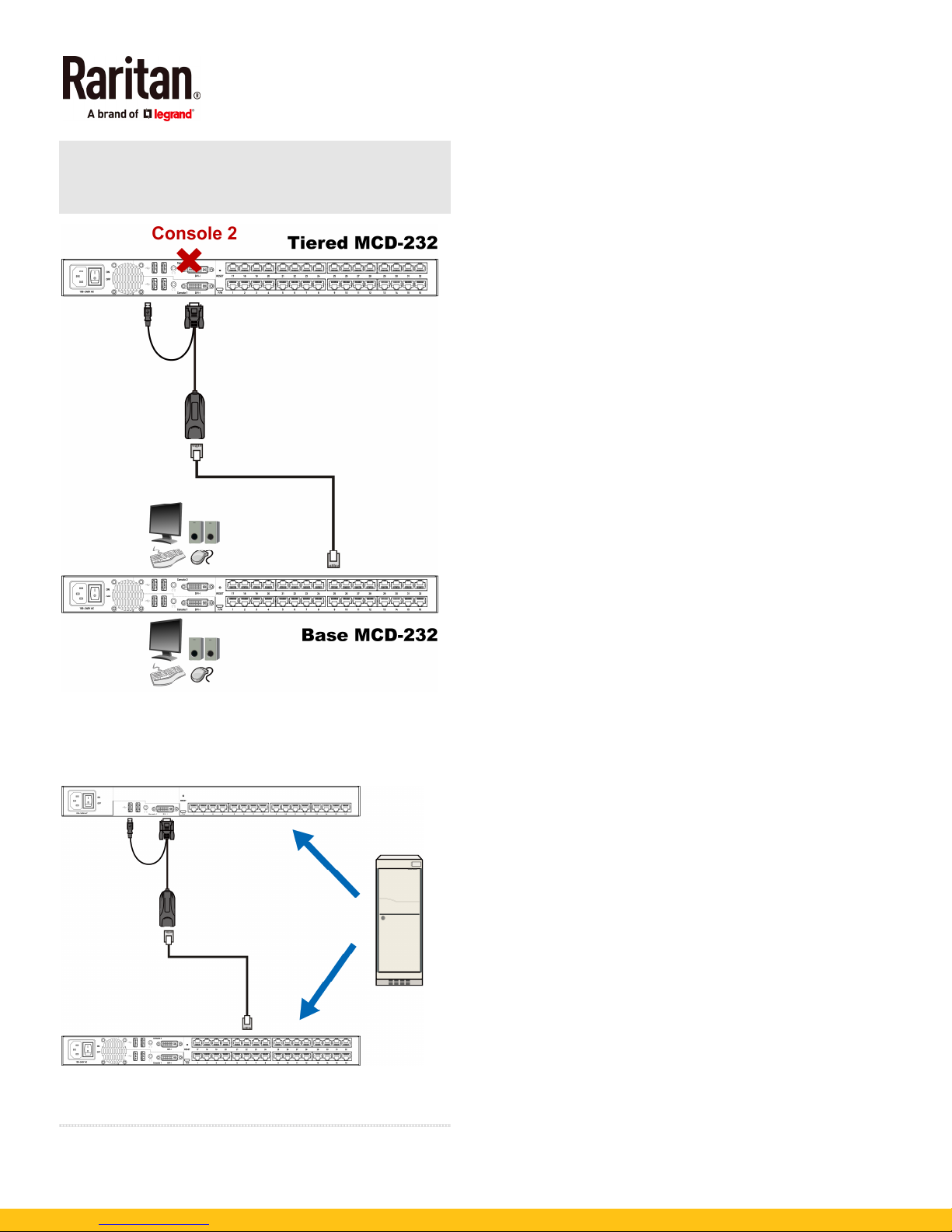
Warning: If any 2nd-tier switch is a dual-user MCD model,
DO NOT connect a keyboard, mouse and monitor to
Console 2 because Console 2 is disabled.
Additional Information
For more information about the MCD and the entire Raritan
product line, see Raritan's website (www.raritan.com). For
technical issues, contact Raritan Technical Support. See the
MasterConsole Digital (MCD) Support page in the Support
section on Raritan's website for additional documentation and
for technical support contact information worldwide.
Step (c): Connect Servers
You can connect servers to any channel ports in the two-tier
system, including those on the base and second-tier switches.
For details on server connections, see
page 3).
QS Rule
Basic Installation
(on
MasterConsole Digital QSG 8
QSG-MCD-0A-v1.0.0-E 255-20-0008-00 RoHS
 Loading...