

Raritan Elegance, Marine Elegance Installation And Maintenance Instructions Manual
Marine
EleganceElegance
Elegance
EleganceElegance
Toilet
Installation and Maintenance Instructions
THE FOLLOWING ARE CAUTIONARY STATEMENTS THAT MUST BE READ AND
FOLLOWED DURING BOTH INSTALLATION AND OPERATION.
WARNING: Raritan Engineering Company, Inc. recommends that a qualified person or electrician install
this product. Equipment damage, injury to personnel or death could result from improper
installation. Raritan Engineering Company, Inc. accepts no responsibility or liability for
damage to equipment, injury or death to personnel that may result from improper installation
or operation of this product.
WARNING: HAZARD OF SHOCK OR FIRE
Always use recommended fuse, circuit breaker and wire size.
Motors used with this product are “Ignition Protected”. They are not however, explosion-
proof as defined in 46CFR 110.15-65(e), Subchapter J-Electrical Engineering.
DO NOT run continuously for more than 30 seconds.
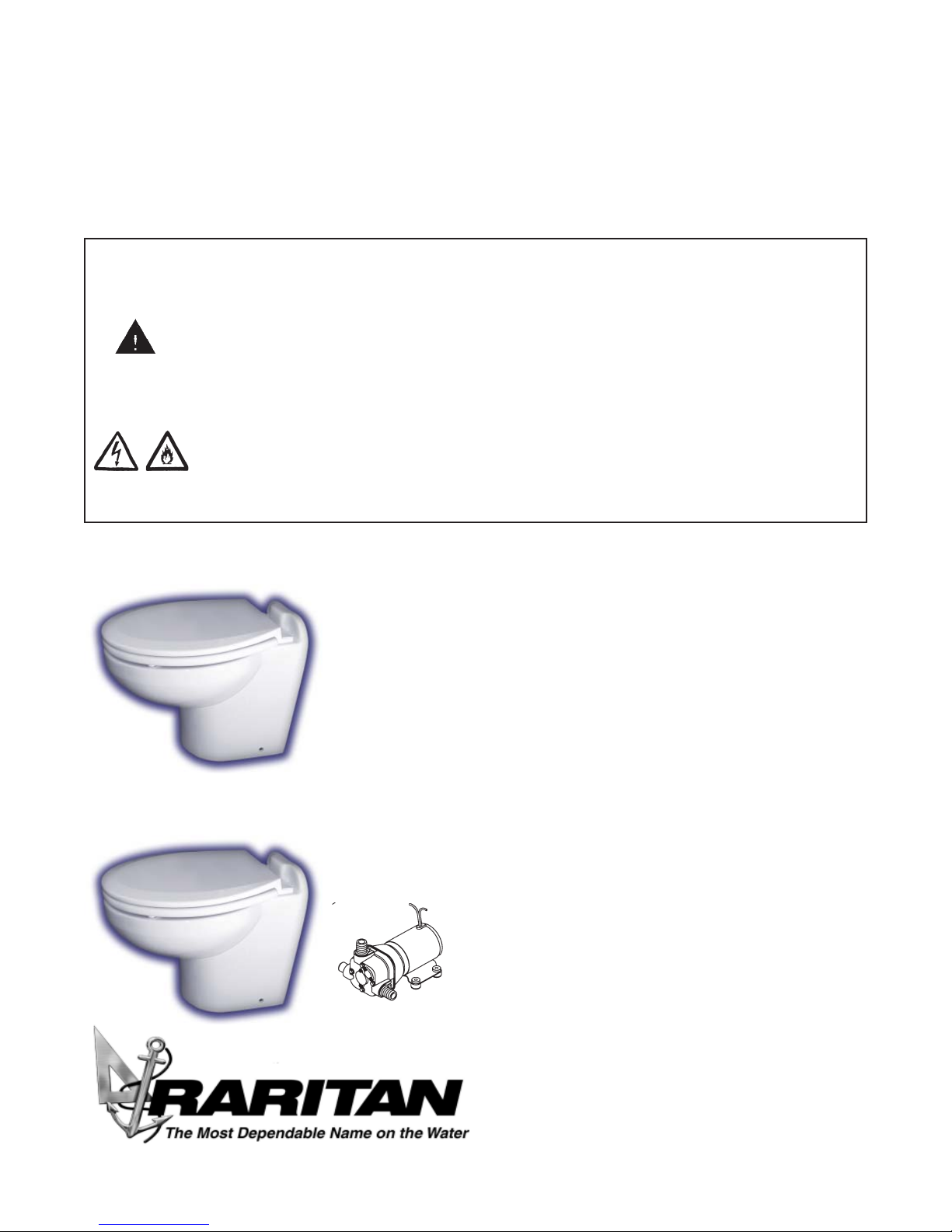
Pressurized
Freshwater Model
Sea Water Model
(Remote Pump)
Desription:
Marine elegance toilet is available in 12V or 24V
DC. Bowls are available in four models: standard with
angled back, standard with straight back, tall with
angled back and tall with straight back.Fresh water
model utilizes onboard freshwater, the Sea water
model utilizes a remote pump installed between raw
water source and bowl. Sea/Fresh model can switch
between fresh and raw water source.
Three different control options are available:
1. Smart flush control: provides timed operation
and independant control of water and discharge
2. ME toilet control: provides momentary opera-
tion and independant momentary control of water
and discharge
3. Push button switch: providing only the ability to
flush with no independant control of water or
1-800-352-5630
www.raritaneng. com
IMPORT ANT SAFETY INSTRUCTIONS:
WARNING: HAZARD OF FLOODING - Always shut off seacock(s) before leaving the boat unattended.
Double clamp all below waterline hose fittings and check frequently for integrity.
T oilets mounted at or below the waterline must have a
SAFETY
vented loop installed in the discharge line. The top of
the vented loop must be a minimum of 4" (10cm) above
the waterline at the boats greatest angle of heel (see
vented loop manufacturer’s instructions).
Sea W ater Models must also have a vented loop installed
between the intake pump and the toilet bowl.
Double clamp all below waterline connections.
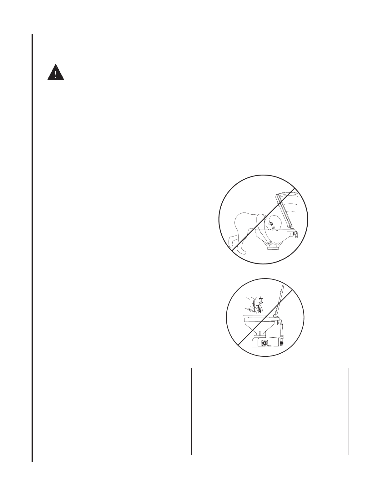
WARNING:
Y oung children should NOT be left unsupervised
around toilet. Serious injury or death could
occur.
Children can drown in water retained in the
bowl.
Seat and/or lid could close and strike child.
Always replace circuit breaker and fuses with
same rating . Use Raritan parts
to maintain ignition protection
requirements.
Recommended Visual Inspection
33
3 For leaks at toilet and hose connections
33
33
3 Hose clamps
33
33
3 Condition of hoses
33
33
3 Seacocks
33
33
3 Condition of wires and connections
33
33
3 In-Line Strainer (if you have one)
33
• No special toilet paper is required.
• Water should appear in the bowl within ten
seconds. If not, see troubleshooting section.
• Hard objects or stringy substances (paper towels,
feminine hygiene products, filter cigarettes, etc.)
must not be thrown into the toilet as they will cause
damage.
• Always shut off seacock(s) before leaving the boat
unattended.
2
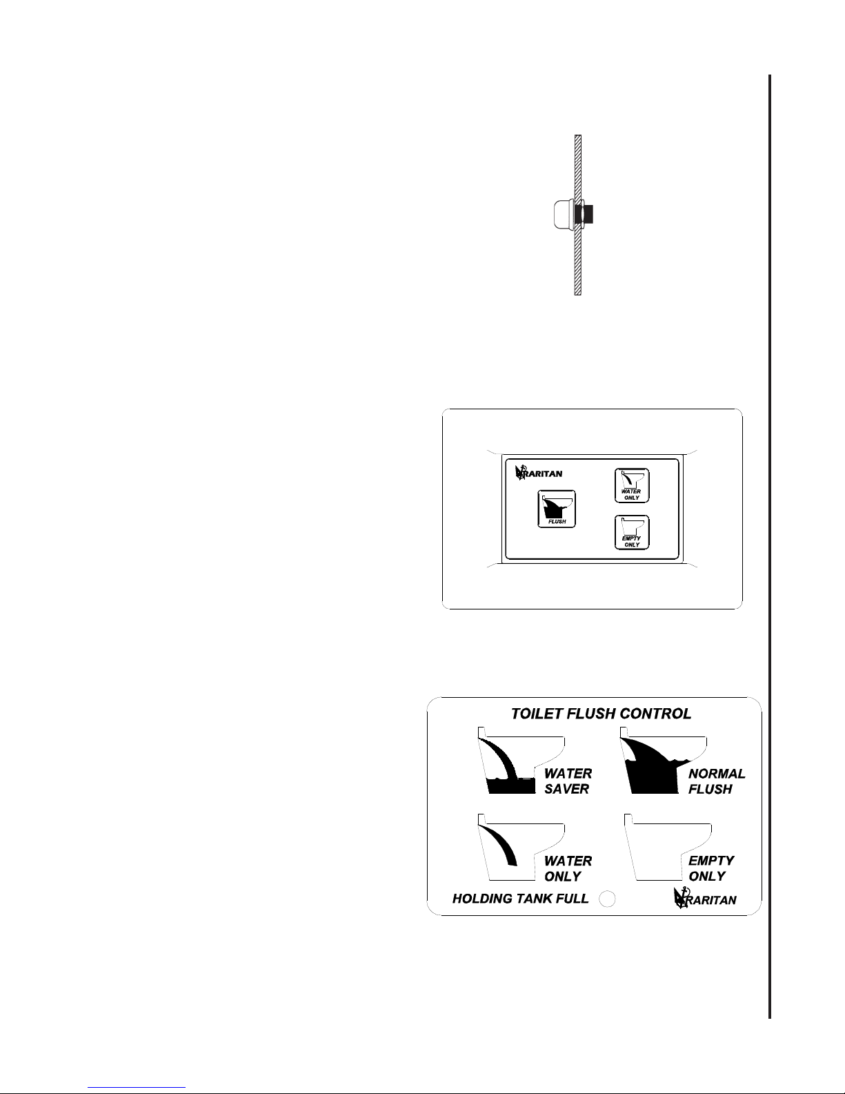
A. Push Button Switch:
Press push-button switch and hold until all waste
is cleared from the toilet bowl.
B. ME T oilet Contr ol:
1. Press and hold “W ater Only” to add water
to the bowl
2. Press and hold “Empty” to evacuate the bowl
3. Press and hold “Flush” to bring water in
while bowl is evacuating
OPERATION
C. Multifunction Smart Switch:
1. Empty Only:Press Empty Only button to
evacuate the bowl. Discharge pump runs as
long as this button is held.
2. W ater Only: Press W ater Only switch to
add water in the bowl. Inlet water solenoid/
pump runs as long as button is pressed with
a seven seconds limit. After limit is reached
W ater Only button is disabled to prevent
overflow of the bowl. T o enable again, Empty
Only button must be pressed.
3. Normal: Press normal button once and
timed flushing cycle starts.
4. W ater saver: Press the button and a water
saver cycle starts.
NOTE: Holding tank full light will only illuminate if
the tank sensor has been added to the control.
3

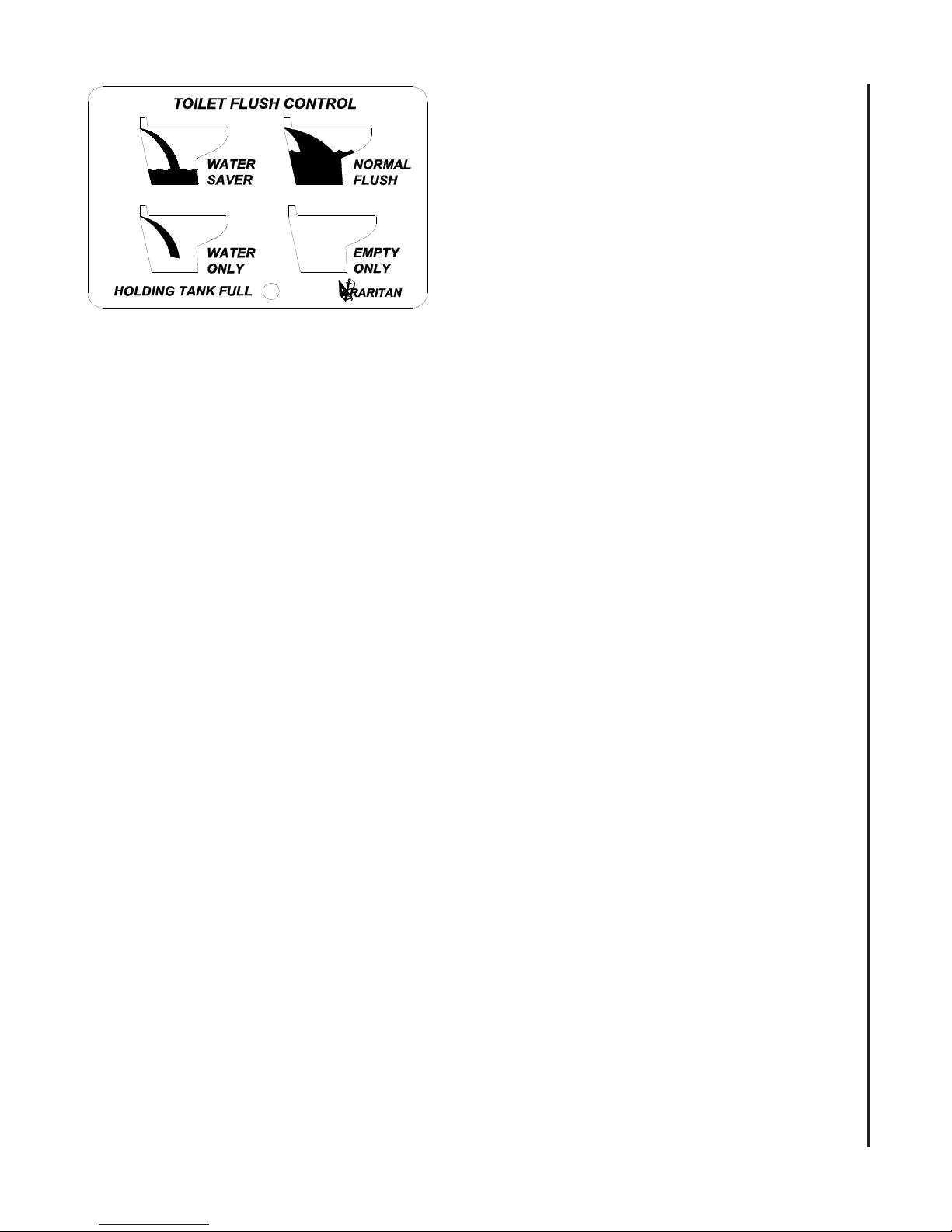
Programming of Toilet Flush Control
NOTE: Flush control is set at factory to work in most
installations and no additional programming is needed.
Use following instructions to re-program if adjustment
on water levels and timings are needed.
Programming timing for “NORMAL” flush cycle:
Normal cycle has initial fill time (T1), Discharge pump
time (T2), and water retention fill time (T3). All three
times (T1,T2 and T3) are programmable.
Factory setting : T1=3 sec, T2=2 sec, T3= 3 sec,
T o change any of the above settings re-programming is
needed
OPERATION
Step 1 – Placing the unit in program mode:
Hold the WATER ONLY & EMPTY buttons down
together for three seconds. The Holding Tank Full
LED will give three quick flashes indicating you have
entered program mode - release both buttons.
Setting T1 initial fill time:
After placing the unit in program mode (Step 1 above)
push the “Normal Flush” button the number of times
required for the Water Valve/Inlet Pump time (one
push = 1 sec’s, two = 2 sec’s., etc.) the Tank LED
will flash once indicating a valid key push.
Note: If the button is pushed 9 times it will start back
at 2 seconds. Once this is done, push the EMPTY
button to store this value (the unit will flash three times
indicating the time has been set and you have left
program mode).
Setting T2 Discharge Pump Time:
After placing the unit in program mode (Step 1 above)
push the EMPTY button the number of times required
for the Discharge Pump time (one push = one second,
etc.) the Tank LED will flash once indicating a valid
key push.
Note: If the button is pushed 9 times it will start back
at 1 second. Once this is done push the NORMAL
button to store this value (the unit will flash three times
indicating the time has been set and you have left
program mode).
Setting T3 Water retention fill Time:
After placing the unit in program mode (Step 1 above)
push the WATER ONLY button the number of times
required for the Water Valve/Inlet Pump time (one
push = ZERO sec’s, two = 1 sec. three = 2 sec’s.,
etc.) the Tank LED will flash once indicating a valid
key push. Note: If the button is pushed 9 times it will
start back at zero.
Once this is done push the “NORMAL” button to
store this value (the unit will flash three times
indicating the time has been set and you have left
program mode).
Programming the WATER ONLY Disable
Features:
1. Hold the WATER ONLY & EMPTY buttons
down together for three seconds. The holding
tank full LED will give THREE flashes indicating you have entered program mode .
2. Push the WATER SAVER button. TheWATER
ONLY and EMPTY buttons now can be disabled or enabled:
3. Pushing the WATER ONLY button will disable
both WATER ONLY and EMPTY buttons. The
holding tank full LED will give THREE flashes
indicating you have left program mode.
Repeat steps 1 to 3 to re-enable these buttons.
The WATER ONLY button can be set to only
work after the EMPTY button has been
pushed: (prevents children from flooding the toilet)
To program this feature
1. Repeat steps 1 and 2 above
2. Pushing the EMPTY button will enable this
feature. The holding tank full LED will give
THREE flashes indicating you have left
program mode. Repeat steps 1 and 2 to disable
these features.
Programming the Holding Tank Full Lockout
Disable Features:
1. Hold the WATER ONLY & EMPTY buttons
down together for three seconds. The holding
tank full LED will give THREE flashes indicating you have entered program mode .
2. Push the WATER SAVER button. This will
place control in disable/enable mode
3. Pushing the WATER SAVER button again. The
holding tank full LED will give THREE flashes
indicating you have left program mode.
Repeat steps 1 to 3 to re-enable Holding Tank Full
Lockout feature..
4
Winterizing:
• Improper winter lay up is a major cause of marine
toilet failure.
• Use only nontoxic antifreeze.
• Flush toilet several times to clear waste from
system.
• Dispose of all antifreeze in accordance with local
and federal regulations.
• Winterize holding tanks, plumbing, treatment
systems (MSD’s), etc. independently following
manufacturer’s instructions.
Pressurized Freshwater Models
Integral and Remote Intake Pump Models
WINTERIZING
Parts Required
3/4" (19 mm.) I.D. intake hose approximately 3 feet
(1 m.) long.
1" (25 mm.) or 1 1/2" (38 mm.) I.D. discharge hose
approximately 3 feet (1 m.) long.
T wo buckets
Nontoxic antifreeze approximately 1 quart (1 liter)
Steps
1. Close the intake and discharge seacocks.
2. T urn off power to unit.
3. Disconnect and drain intake hose and discharge
hose .
4. Connect short hoses to toilet’ s intake and discharge.
5. Place one bucket under hose connected to toilet’s
discharge.
6. Pour nontoxic antifreeze in other bucket.
7. Place hose connected to intake pump into bucket
with antifreeze.
8. Turn on power to unit and flush toilet until
antifreeze begins to be discharged from toilet.
9. Disconnect power from toilet.
Parts Required
• 1" (25 mm.) or 1 1/2" (38 mm.) I.D.
discharge hose, approximately 3 feet (1 m.) long
• T wo buckets
• Nontoxic antifreeze approximately 1 quart
(1 liter)
Steps
1. Close discharge seacock (if one exists).
2. Shut off intake water at source.
3. T urn off power to unit.
4. Disconnect and drain discharge hose.
5. Disconnect intake hoses from water solenoid and
place in one of the buckets.
6. Connect short hose to toilet’ s discharge and place
in other bucket.
7. Pour antifreeze in bowl.
8. Turn on power to unit and flush until antifreeze is
removed from the bowl and water is drained from
the solenoid and hose.
9. Disconnect power to toilet.
10. Reconnect intake hoses to water solenoid
RECOMMISSIONING
1. Using the buckets, hoses and approximately one
gallon (3.8 liters) of clean fresh water, flush
antifreeze out of the toilet (see Winterizing).
Dispose of antifreeze in accordance with local
and federal regulations.
2. Reconnect the intake and discharge hoses and
open both seacocks and water source valve.
3. Check all connections for leaks with several test
flushes.
SYSTEM START-UP
1. Open seacock(s).
NOTE: Pressurized freshwater models; open water
source valve.
2. Turn on power to toilet.
3. Flush toilet per Operation Instructions.
4. Check for leaks.
IMPORTANT: If toilet does not flush properly
or if water does not enter the bowl within 10
seconds, refer to Troubleshooting.
5
Plumbing
pmupekatnIfonoitcusmumixaM
thgiehmumixaM .teliotfoesabmorf)m3(.tF01
stnemeriuqer
ecruosretawdezirusserP muminim
NOTES: for Wiring
.1
.2
.3
.4
.5
natsiD
.pmupekatnietomer
)enilretawevobathgiehmumixaM(
pooldetnevegrahcsidfo
foetarwolf
)apK07(isp01
.pmuPekatnImorf)m2.1(.tF4
ta)sretil52.31(mpg5.3
.)aPk5.43(isp5foerusserpffotuhs
.ecruosotkcabdnatinuotecruosmorferasecnatsiD
nehwdedulcniebTSUMpmupekatnietomerotecruosrewopmorfec
dnaesabrewolrofdesuebTSUMeziseriwemaS.ecnatsidlatotgninimreted
GWA
2
mm
teeF
reteM
Hose Sizes
riwrotcudnocdednemmoceR
CDV42esustinuCAV042/021roF
2
mm(GWAmuminime
o
501nodesaberasezisrotcudnocdednemmoceR
.sgnitarnoitalusnirehtorofsdradnatSCYBAotrefeR
.pordegatlov%3rof)
.noitalusnidetarC
.tinuotremrofsnartmorfsnoitacificeps
INLET
Discharge
CONVERSIONS
Wire - AWG to mm
614121018642
5.15.20.40.60.010.610.520.53
Feet to Meters
01510252030405
1.36.41.66.72.92.212.51
1/2”(12.7 mm.) for freshwater model
3/4” (19 mm.) for sea water model
1”(25.4 mm.) or 1 1/2”(38 mm.)
Sea Water Model - Recommended Wire and Fuse/Circuit Breaker Size
ecnagelE
etomeR
pmuP
ylnO
ward.pmA
lanimon@
egatlov
51
teef
02
teef
03
stinU
egatloV
tiucriC
SPECIFICATIONS
teliot
esuf/rekaerB
)spma(ezis
ward.pmA
lanimon@
/egatloV
2
teef
04
teef
05
teef
CDV21038101
CDV4202015
GWA01GWA8GWA6GWA6GWA4
GWA41GWA41GWA21GWA01GWA01
Pressurized Freshwater Model - Recommended Wire and Fuse/Circuit Breaker Size
stinU
egatloV
tiucriC
)spma(ezis
CDV215281
CDV425101
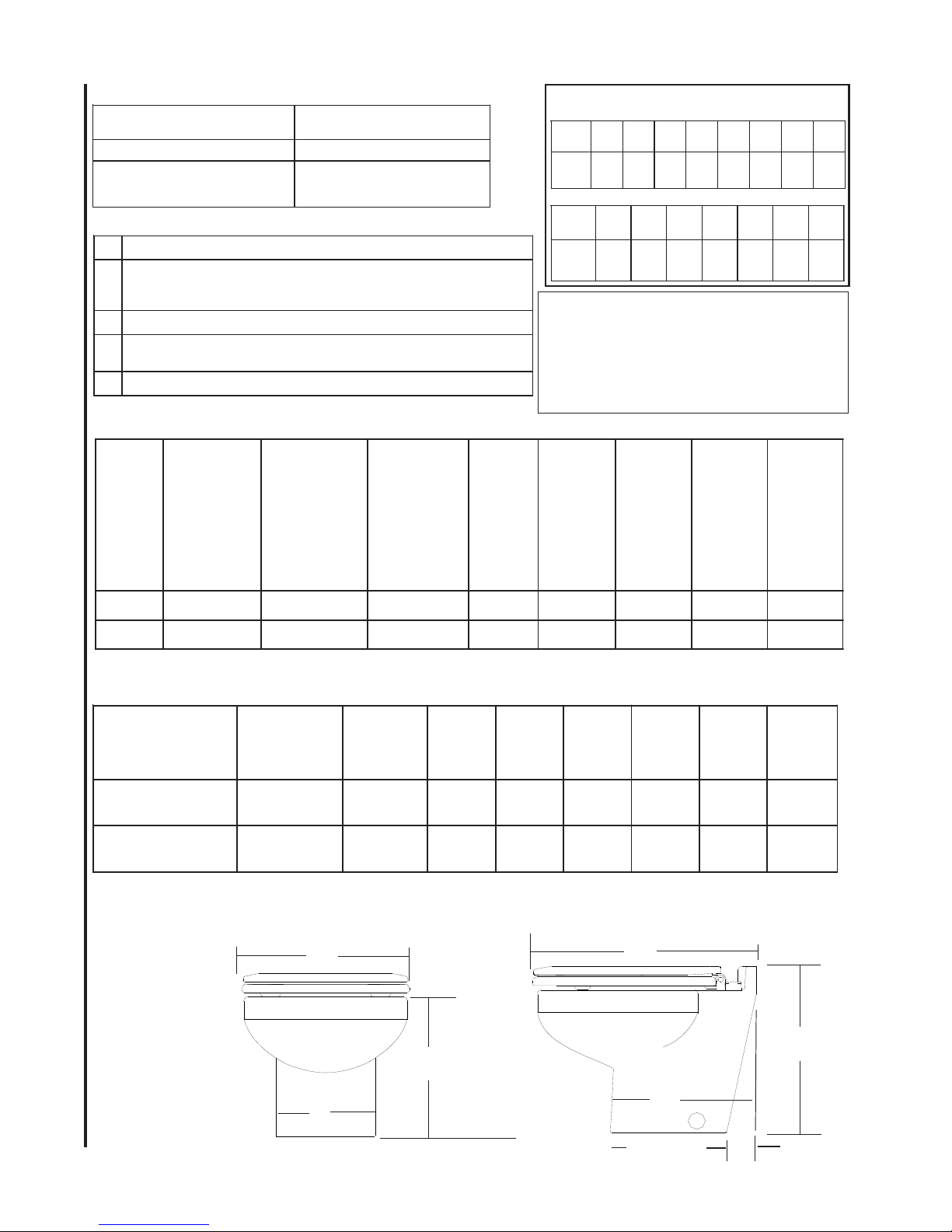
SIZE
E
esuf/rekaerB
ward.pmA
egatlov
01
lanimon@
teef
51
teef
02
teef
03
teef
04
teef
05
teef
GWA21GWA01GWA01GWA8GWA6GWA6
GWA41GWA21GWA01GWA01GWA8GWA6
A
See Table
C
D
F
B
6
G
 Loading...