

Raritan II, Paragon II, Paragon II P2-UMT242, Paragon II P2-UMT442, Paragon II P2-UMT832M User Manual

User Manual
Paragon II

This page intentionally left blank

User Manual
Paragon II
Copyright © 2003 Raritan Computer, Inc.
PII-0A-E
December 2003
255-30-6000
Raritan Computer Inc.
400 Cottontail Lane
Somerset, NJ 08873
USA
Tel. 1-732-764-8886
Fax. 1-732-764-8887
E-mail: sales@raritan.com
http://www.raritan.com
Raritan Computer Europe, B.V.
Eglantierbaan 16
2908 LV Capelle aan den IJssel
The Netherlands
Tel. 31-10-284-4040
Fax. 31-10-284-4049
E-mail: sales.europe@raritan.com
http://www.raritan.com
Raritan Computer Japan, Inc.
Kuga Building 7F
11-6, Kuramae 4-chome
Taitoo-ku, Tokyo 111-0051, Japan
Tel. 81-3-5833-6360
Fax. 81-3-5833-6336
E-mail: sales.japan@raritan.com
http://www.raritan.co.jp
Raritan Computer Taiwan, Inc.
5F, 121, Lane 235,
Pao-Chiao Rd., Hsin Tien
Taipei Hsien, Taiwan, ROC
Tel. 886-2-8919-1333
Fax. 886-2-8919-1338
E-mail: sales.asia@raritan.com
http://www.raritan.com.tw

This page intentionally left blank

FCC Information
This equipment has been tested and found to comply with the limits for a Class A digital device, pursuant
to Part 15 of the FCC Rules. These limits are designed to provide reasonable protection against harmful
interference in a commercial installation. This equipment generates, uses, and can radiate radio frequency
energy and if not installed and used in accordance with the instructions, may cause harmful interference to
radio communications. Operation of this equipment in a residential environment may cause harmful
interference.
Product names mentioned in this document are trademarks or registered trademarks of their respective
companies. Z-Series, Paragon, MasterConsole MX
MasterConsole SMX, ConsoleSwitch and their respective logos are registered trademarks of Raritan
Computer, Inc. PS/2, RS/6000, and PC/AT are registered trademarks of International Business Machines
Corporation. Apple and Macintosh are registered trademarks of Apple Computer, Inc. Lexan is a registered
trademark of GE. Windows is a registered trademark or trademark of Microsoft Corporation in the United
States and other countries. Sun is a registered trademark of Sun Microsystems. All other marks are the
property of their respective owners.
4
, MasterConsole MXU2, MasterConsole II,
Japanese Approvals
Contact Raritan Technical Support Team at (732) 764-8886 or e-mail us at support@raritan.com
Ask for Technical Support – Monday through Friday, 8:00am to 8:00pm, EST.


TABLE OF CONTENTS i
Table of Contents
Chapter 1: Introduction .................................................................. 1
Paragon II Overview...................................................................................................................1
Product Photos...........................................................................................................................2
Product Features........................................................................................................................3
Package Contents......................................................................................................................4
Chapter 2: Installation.................................................................... 5
Basic Installation........................................................................................................................5
Initial Administrative Testing ......................................................................................................7
Paragon II Front Panel Display and Controls ............................................................................8
Initial Configuration ..................................................................................................................12
Using the OSUI for Initial Configuration...................................................................................12
Installing a Paragon System with a Single Base Unit..............................................................13
Installing a Cascaded Paragon System...................................................................................17
Installing a Paragon Stacking Switch................................................................................20
Chapter 3: Operation – User Functions ........................................ 21
Login.........................................................................................................................................21
Selecting a Server....................................................................................................................23
User Customization..................................................................................................................26
User Profile Parameters and How to Change Settings.....................................................27
Help Menu................................................................................................................................28
Keyboard-Controlled OSUI Functions......................................................................................29
Information Menu.....................................................................................................................30
Chapter 4: Operation – Administrator Functions ......................... 31
The Administration Menu.........................................................................................................31
Guidelines for System Configuration .......................................................................................32
System Configuration...............................................................................................................32
User Configuration...................................................................................................................34
Channel Configuration .............................................................................................................36
User Station Profile..................................................................................................................38
Keyboard Type ..................................................................................................................38
Video Delay .......................................................................................................................38
Group Settings (Access Rights)...............................................................................................39
Recommendations...................................................................................................................40
Network Settings......................................................................................................................41
Autoscanning and Autoskipping...............................................................................................42
Power Management.................................................................................................................43
Configuring and Naming the Power Strip..........................................................................43
Associating a Target with a Power Outlet .........................................................................43
Controlling Power to an Outlet...........................................................................................44
Paragon II Network Port...........................................................................................................44
Chapter 5: Paragon II and Z-CIM .................................................. 45
Connecting Z-CIMs as Tiers ....................................................................................................46
Chapter 6: IBM x330 ..................................................................... 49
Chapter 7: Configurations ............................................................ 51
Principles of Re-Connection ....................................................................................................51
Tiered Configurations...............................................................................................................52
Standard Tiering Configurations........................................................................................52
Stacked Configurations............................................................................................................54
Standard Stacking Configurations.....................................................................................55
Non-Standard Tier Configuration.............................................................................................58
Guidelines for Existing Firmware Versions........................................................................58

ii PARAGON II USER MANUAL
Illegal Configuration .................................................................................................................62
Loop-Back Configuration..........................................................................................................62
Appendix A: Specifications .......................................................... 63
CAT5 Cable Guidelines............................................................................................................64
Appendix B: User Station Direct Mode ........................................ 65
Appendix C: Configuration and Compatibility.............................. 67
Configuration Matrix.................................................................................................................67
Compatibility Matrix..................................................................................................................67
Appendix D: Paragon II Rack Mount ............................................ 69
Forward Mount.........................................................................................................................69
Rear Mount ..............................................................................................................................70
Appendix E: Using AUATC for RS-232 Access ............................. 71
Introduction to the AUATC.......................................................................................................71
Installing the AUATC................................................................................................................71
Operating the AUATC..............................................................................................................72
Screen Layout ...................................................................................................................72
On-Line Mode....................................................................................................................73
Help Mode .........................................................................................................................73
Buffer Edit Mode................................................................................................................74
Configuring the AUATC............................................................................................................75
Troubleshooting the AUATC....................................................................................................77
Appendix F: Emulating Sun Keys with a PS/2 Keyboard ............. 79
Appendix G: Troubleshooting....................................................... 81
Multi-Tier Installation................................................................................................................82
Appendix H: FAQ........................................................................... 83

TABLE OF FIGURES iii
Table of Figures
Figure 1 Paragon II Base Units ........................................................................................................2
Figure 2 P2-UMT832, P2-UST, and P2CIM-PS2.............................................................................2
Figure 3 Installation Diagram............................................................................................................6
Figure 4 Login Menu.........................................................................................................................7
Figure 5 Selection Menu...................................................................................................................7
Figure 6 Paragon II Front Panel Buttons..........................................................................................8
Figure 7 LCD Normal Display...........................................................................................................9
Figure 8 Power Up Clear Database..................................................................................................9
Figure 9 LCD Functions....................................................................................................................9
Figure 10 Function Selection............................................................................................................9
Figure 11 Display Ver. and SN.......................................................................................................10
Figure 12 User Station Test............................................................................................................10
Figure 13 Channel CIM (UKVM) Test............................................................................................10
Figure 14 Stacking Support............................................................................................................10
Figure 15 Set LCD Contrast...........................................................................................................10
Figure 16 Auto Configure ...............................................................................................................11
Figure 17 Format of OSUI screens.................................................................................................12
Figure 18 Rear panel of a Paragon User Station and P2-UMT832M unit.....................................13
Figure 19 Login Menu for a P2-UMT832M.....................................................................................14
Figure 20 Selection Menu for a P2-UMT832M...............................................................................14
Figure 21 Administration Menu.......................................................................................................15
Figure 22 Channel Configuration Menu of a P2-UMT832M...........................................................16
Figure 23 Sample cascaded system ..............................................................................................17
Figure 24 Selection Menu...............................................................................................................18
Figure 25 Administration Menu.......................................................................................................18
Figure 26 Channel Configuration Menu for a P2-UMT832M..........................................................19
Figure 27 Login Menu for a P2-UMT832M.....................................................................................21
Figure 28 Selection Menu for a P2-UMT832M...............................................................................22
Figure 29 Selection Menu in order by Channel Port Number ........................................................23
Figure 30 Selection Menu in order by Name..................................................................................24
Figure 31 User Profile Menu...........................................................................................................26
Figure 32 Help Menu......................................................................................................................28
Figure 33 Information Menu ...........................................................................................................30
Figure 34 Administration Menu.......................................................................................................31
Figure 35 System Configuration Menu...........................................................................................32
Figure 36 The “left end” of the User Configuration Menu...............................................................34
Figure 37 The “right end” of the User Configuration Menu ............................................................35
Figure 38 The “left end” of the Channel Configuration Menu.........................................................36
Figure 39 The “right end” of the Channel Configuration Menu.......................................................37
Figure 40 User Station Profile Screen............................................................................................38
Figure 41 Network Settings Menu..................................................................................................41
Figure 42 Connecting a Z-CIM as a Tier to Paragon II ..................................................................46
Figure 43 IBM x330 Tiered from a Paragon II Matrix Switch ........................................................49
Figure 44 Single Base Configuration..............................................................................................52
Figure 45 Multiple Base Configuration ...........................................................................................53
Figure 46 Stacking - Single Base Configuration with P2-UMT1664M and P2-UMT1664S............55

iv PARAGON II USER MANUAL
Figure 47 Stacking - Single Base Configuration with P2-UMT832M and P2-UMT832S................55
Figure 48 Stacking - Single Base Configuration with P2-UMT832M and P2-UMT832S................55
Figure 49 Stacking - Single Base Configuration with P2-UMT832M and P2-UMT832S................56
Figure 50 Stacking - Single Base Configuration with P2-UMT1664M and P2-UMT832S..............56
Figure 51 Stacking - Single Base Configuration with P2-UMT832M and P2-UMT1664S..............56
Figure 52 Stacking - Single Base Configuration with P2-UMT1664M and P2-UMT832S..............57
Figure 53 Stacking - Single Base Configuration with P2-UMT832M and P2-UMT1664S..............57
Figure 54 Triangle Configuration....................................................................................................59
Figure 55 Diamond Configuration...................................................................................................60
Figure 56 Redundant Configuration ...............................................................................................61
Figure 57 Recommended Redundant Configuration connection scheme......................................62
Figure 58 Illegal Loop-Back Configuration.....................................................................................62
Figure 59 Cat5 Cable Diagram.......................................................................................................64
Figure 60 Front rackmount of a P2 Base Unit................................................................................69
Figure 61 Front rackmount of a P2 User Station............................................................................69
Figure 62 Rear rackmount of a P2 Base Unit.................................................................................70
Figure 63 Rear rackmount of a P2 User Station ............................................................................70
Figure 64 AUATC screen layout (On-Line Mode) ..........................................................................72
Figure 65 Help screen....................................................................................................................73
Figure 66 Buffer Edit Mode screen.................................................................................................74
Figure 67 Setup Communication Screen .......................................................................................75
Figure 68 Set Up Programmable Keys screen...............................................................................76

CHAPTER 1: INTRODUCTION 1
Chapter 1: Introduction
Congratulations on your purchase of Raritan’s Paragon II! The Paragon family is about breaking away from
the traditional, expensive model of server management – one server, one dedicated monitor, one dedicated
keyboard. Paragon allows for a single user station (monitor, keyboard, and mouse) for multiple servers –
even servers of different platforms! Why not a pair of user stations, each of which can control multiple
servers? Why not many monitors or user stations for the same server? Why not access or display any of
your servers, anywhere in the world, with any of your user stations or monitors?
With our Paragon products, there’s no reason why not. We carry a broad line of robust solutions for all
these applications:
• Do you have just two PCs and need an economical alternative to keeping two mice, keyboards, and
monitors on your desk? Or do you need to share many servers, including a mix of IBM PC, RS/6000,
Apple Macintosh, Sun Microsystems, and SGI types among multiple worldwide users with different
access levels?
• Do you have to send video from one server to two different local monitors? Or do you need to send
video from multiple servers to dozens of remote monitors?
• Does your switch have to sit solidly on a worktable and use regular everyday cables? Or does it have to
be mounted in an equipment rack, use convenient many-to-one cables, and have a rackmounted user
station that folds and slides into 1U of space?
No matter how large or small your setup, no matter how simple or how complex, Raritan is confident that
there is a Paragon system just right for you. The Paragon family from Raritan – the one-stop answer for all
your video and KVM switching and extension needs!
Paragon II Overview
The Paragon II is designed to perform heavy-duty multiple-user-to-many-server keyboard/video/mouse
(KVM) matrix switching without burdening you with big, confusing hydra-headed cables. Instead, the
Paragon II uses standard Category 5 unshielded twisted-pair (UTP) cabling, like the type that is already
installed at many sites. It can connect users with servers across as much as 1000 ft. (304 m) of such cabling.
Paragon II systems consist of three components: Base Units, which do the matrix switching; ComputerInterface Modules (CIMs) connected to each server; and User-Station Modules (User Stations) connected
to each set of user-station equipment.
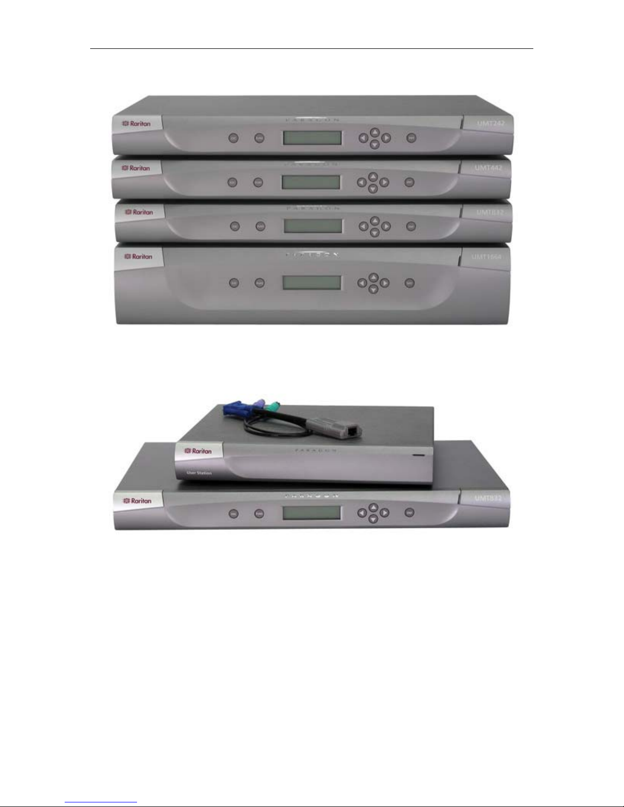
There are a number of Base Unit models that support different numbers of directly attached users and
server CPUs:
• Product code P2-UMT242 supports 2 users and 42 CPUs
• P2-UMT442 supports 4 users and 42 CPUs
• P2-UMT832M supports 8 users and 32 CPUs
• P2-UMT1664M supports 16 users and 64 CPUs
There are also several different CIMs for different types of servers (all must output VGA video):
• P2CIM-PS2 and ZCIM-PS2 support CPUs with IBM PS/2 type keyboard and mouse ports; Z-CIM has
an extra RJ-45 port to support a “local CPU” installed between a User Station and a Base Unit, as well
as chaining of ZCIMs for clustered access.
• P2CIM-SUN supports CPUs with Sun type keyboard and mouse ports
• P2CIM-USB and P2CIM-SUSB support CPUs with USB keyboard and mouse ports
• AUATC supports CPUs connected through their RS-232 serial ports
There is one universal User Station (P2-UST) that supports PS/2, Sun, or USB keyboards and mice. (We
recommend that you use a Sun keyboard if there are any Sun CPUs in your system; if you must use a PS/2
keyboard to control Sun CPUs, please see Appendix F: Emulating Sun Keys with a PS/2 Keyboard for
additional information.) If you want to connect one user station to one CPU across a long stretch of CAT5
or higher cable, you can run such a cable between a “direct mode” User Station and a P2CIM-PS2 (please
see Appendix B: User Station Direct Mode for additional information).
2 PARAGON II USER MANUAL
Product Photos
Figure 1 Paragon II Base Units
Figure 2 P2-UMT832, P2-UST, and P2CIM-PS2

CHAPTER 1: INTRODUCTION 3
Product Features
• 2U design supports 16 users, 64 servers (model P2-UMT1664M)
• 1U design supports 8 users, 32 servers (model P2-UMT832M)
• 1U design supports 4 users, 42 servers (model P2-UMT442)
• 1U design supports 2 users, 42 servers (model P2-UMT242)
• Expands to 32 users with Raritan’s UKVMP2 or CIMPAC8
• Expands to 64 users with Raritan’s HUBPAC8
• Locates users and servers up to 1,000 feet apart
• Supports high-resolution video – up to 1600 x 1200
• Supports up to 512 customized user profiles (with optional Memory Card)
• Adds remote access over IP or modem with Raritan’s IP-Reach
• Expands to 10,000 servers via multi-dimensional expansion (with optional Memory Card)
• Stacking switches provide 100% non-blocked expansion with a single cable
• Enclosed 19” rack mounts with included brackets
• Simple plug-and-play auto-configure installation
• Hot-swappable components with no impact on server operation
• Platform-specific CIMs for PS/2, Sun, USB, Sun USB, ASCII/serial devices
• Powerful, intuitive on-screen user interface for simple operation
• Flexible, multi-level security for authorized server access
• Three system operation modes - private, public, and share
• Flash firmware upgrades via network port
• Paragon Manager™ Windows application provides streamlined administration of Paragon II
infrastructure, including adding, deleting or modifying user profiles, event logging, and database
backup/restore
• OSUI support for IBM x330 with C2T technology
• Seamless compatibility with Raritan’s MasterConsole MXU2 and Z-Series 4200U
• Administrator can logoff any connected user
• Turn on, off, or reboot power to any connected device
• Network admin port
• Set power control permissions on a per outlet basis

4 PARAGON II USER MANUAL
Package Contents
Each Paragon Base Unit (P2-UMT242, P2-UMT442, P2-UMT832M, or P2-UMT1664M) ships with:
• (1) Base Unit
• (2) 20-ft. (6.1-m) CAT5 test cables
• (1) Pair of rackmount brackets and associated screws
• (1) 6-ft. (1.8-m) AC power cord
• RUMT-1U-LM304 Rackmount kit
• CAT5 admin cable
• Raritan’s User’s Manual CD
• Quick Setup and Installation Guide
The Paragon Stacking Units ship with:
• (1) Stacking Switch
• RUMT-1U-LM304 Rackmount kit
• 6” Stacking Cable (P2-UMT832M) or 12” Stacking Cable (P2-UMT1664M)
• AC Power Cord
The Paragon User Station ships with:
• (1) User-Station Module
• (1) 6-ft. (1.8-m) AC power cord
• (1) 6-ft. (1.8-m) AC power-extension cord for the attached monitor
• (1) 10-ft. (3-m) DB9 male-to-female serial administration cable

CHAPTER 2: INSTALLATION 5
Chapter 2: Installation
Important! The Paragon and all devices you want to attach to it must be unplugged and powered
OFF prior to installation.
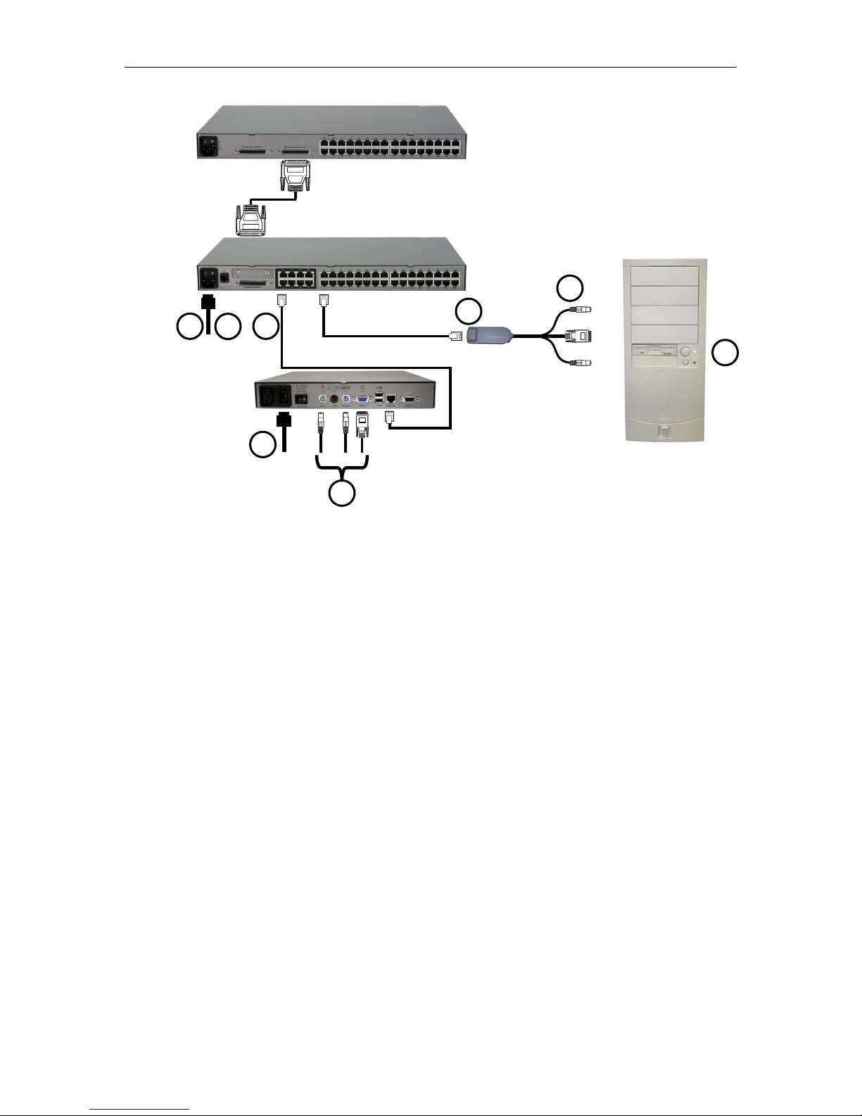
Basic Installation
1. Connect power cord to the Main Switching Unit.
Optional Stacking Support:
− Connect power cord to a Stacking Unit.
− Connect one end of a stacking cable to the "Expansion Port Out" on the back of the Stacking Unit.
Connect the other end of the cable to the "Expansion Port" on the Main Switching Unit
− Power ON all switching units
− On the front panel LCD of the Main Switching Unit:
Press the [FUNC] button and use the [] and [] keys to select "Stacking Support." Press
the [ENT] button.
Select the total number of Stacking Units desired (0-3). Press the [ENT] button.
− On the front panel LCD of the Stacking Unit:
Press the [FUNC] button and use the [] and [] keys to select "Set Stack ID." Press the
[ENT] button.
Assign the Stacking Unit ID using the [] and [] keys. Each Stacking Unit MUST HAVE
A UNIQUE ID (1-3)
− Press the [ENT] button (sequential order is not necessary).
2. Power ON the Main Switching Unit.
3. Connect one end of a Category 5e UTP cable to User Port #1 on the back of the Main Switching Unit.
Connect the other end of the cable to the “Cat5 Port” on the back of the User Station (P2-UST)
4. Connect a power cord to the User Station. Power ON the User Station.
5. Connect a PS/2 keyboard, mouse, and VGA monitor to the User Station. Power ON the monitor.
6. Connect one end of a Category 5e UTP cable to Channel Port #1 on the back of the Main Switching
Unit (or Stacking Unit, if attached). Connect the other end of the cable to the RJ45 port on a Computer
Interface Module (P2-CIM).
7. Connect the P2-CIM to server’s keyboard, video, and mouse ports.
8. Power ON server.
Repeat steps 3 through 8 for all other CPUs you want to attach.
6 PARAGON II USER MANUAL
3456782
Optional
1
Figure 3 Installation Diagram

CHAPTER 2: INSTALLATION 7
Initial Administrative Testing
To verify that an attached server can be viewed and controlled through the Paragon system:
1. When you first power ON the Paragon Base Unit, an attached User Station, and the User Station’s
attached monitor; a Login Menu will be displayed on the monitor. Type admin (all lowercase) in the
User Name field and press the [Enter] key. Type raritan (all lowercase) in the Password field and
press the [Enter] key.
Note: The factory-default user names are user01 through up to user16 (depending on the model of the Base
Unit) for regular users and admin for the admin user. User names are not case-sensitive. By default, a
password is required only for the admin user, and that password is raritan. Passwords are case-sensitive.
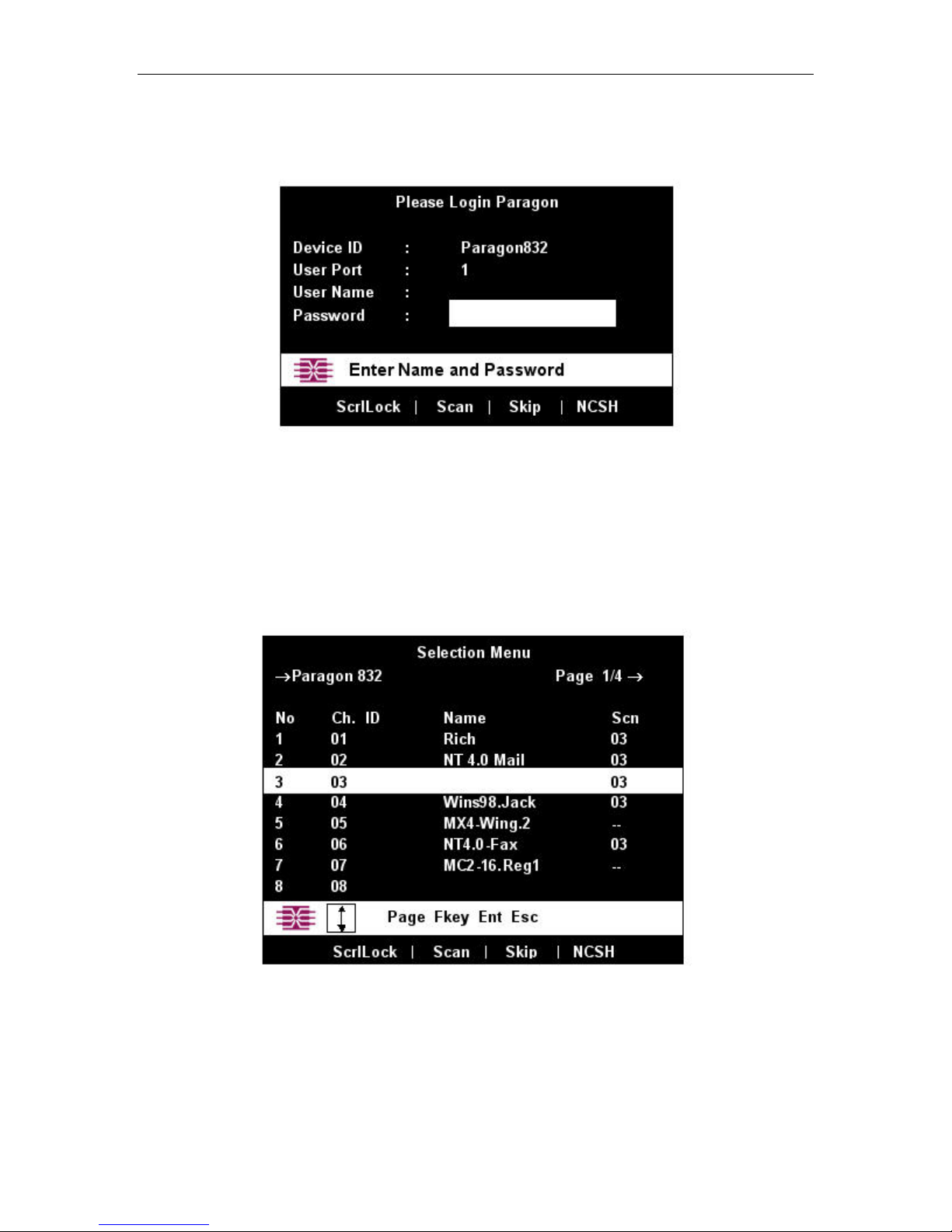
Figure 4 Login Menu
2. The monitor will display an On-Screen User Interface (OSUI) Selection Menu with the port of the
connected CPU displayed in green. (It will have no default name – the Name field will be blank.)
Figure 5 Selection Menu
3. Use the up- and down-arrow keys on the user station’s keyboard to move the highlight to the green
server port and press the [Enter] key.
4. Normal server access and operation indicates a successful connection.

8 PARAGON II USER MANUAL
A video-gain adjustment is available to focus the video image, which can be especially useful if you are
using an LCD flat-panel monitor. To make this adjustment, activate the OSUI (if you have not done so
already) by rapidly pressing the keyboard’s [Scroll Lock] key twice. Use the [+] and [-] (plus- and minussign) keys on the keyboard’s numeric keypad
to adjust the video image until it appears to be in focus.
Paragon II Front Panel Display and Controls
The control buttons and LCD display on the Paragon II unit provide systems management and technical
support functions. For most situations, there is no need to use the front panel beyond viewing status.
ENT
ESC
FUNC
Figure 6 Paragon II Front Panel Buttons
Front Panel Components and Functions:
1. The [ESC] button is used for canceling displayed function and returning system to normal state.
2. The [FUNC] button is used to select various functions.
3. The LCD displays system status and indicates functions that can be selected by pressing front panel
control buttons.
4. The [], [], [], and [] buttons are used for selecting or setting various options, depending on
function being performed.
5. The [ENT] button is used for confirming and executing selected function.
Start-Up Display:
When a Paragon II unit is powered ON, it performs a start-up test. It checks each channel and user port to
ensure proper operation.
Normal Display:
After start-up test, LCD panel displays two lines of messages:
1. Line 1: Running message: “Raritan Computer Paragon II: Paragon832/1 Ready”
For a Paragon II unit model P2-UMT832M, “Paragon832” is the default name of the Matrix Switching
Unit (this name may be changed through the System Configuration Menu).

CHAPTER 2: INSTALLATION 9
2. Line 2: User port status message: “A/N User (1, 2, 3 …) → None”
User port status displays a scrolling status of all user ports, one user port per second. The User’s active
channel, 1 through 256, is displayed after the user port number.
Raritan Computer Paragon II: Paragon832/1
Ready
A User (1, 2, 3 … 8) → None
A=Active User # 1-8
- OR -
Raritan Computer Paragon II: Paragon832/1
Ready
N User (1, 2, 3, … 8) → None
N=Non-Active User # 1-8
Figure 7 LCD Normal Display
Power Up Option:
If you hold down the [FUNC] button on the front panel of the Paragon II unit during Power Up, the
Paragon II unit will clear its database and reset to factory defaults. Confirm functions by pressing the [ENT]
button on the front panel.
Clear Database
Hit Ent/ESC?
Figure 8 Power Up Clear Database
Function Selection Screen:
Several administrative functions can be performed on the Function Selection Screen on the Paragon II
unit’s front panel.
Display Ver./SN
Test User UST1
Test Chan. UKVM
Test Stack Unit
Stacking Support
Set LCD Contrast
Re-Configure
Set IP Address
Reset Unit
Figure 9 LCD Functions
Selecting a Function:
Press the [FUNC] button on the front panel of the Paragon II unit to enter Function Selection mode and use
the [] and [] buttons to scroll through the Function List. Press the [ENT] button on the front panel to
select displayed function and use the instructions below for each specified function. Press the [ESC] button
on the front panel at any time to return to Normal Display.
Function Menu
Display Ver./SN
Figure 10 Function Selection

10 PARAGON II USER MANUAL
1. Display Ver./SN (Firmware Version and Serial Number): Displays current version of firmware and
unit’s serial number.
Firmware: 2C1
SN: CPB80347
Figure 11 Display Ver. and SN
2. Test User UST1 (User Station): Used by administrator to check if user stations (UST1s) are
functioning properly. Press the [] or [] button to change user port number. Display will read “OK”,
“None”, or “Failed. Press [ESC] to return to normal display.”
If a “failed” condition is detected, make sure Category 5e UTP cable is installed properly and secured,
or try using another UST1 to see if UST1 under test has become defective.
Test User UST1
UST1: 3 OK
Figure 12 User Station Test
3. Test Channel UKVM (CIM UKVM): Used by administrator to check if CIM is functioning properly.
Press the [] or [] button to change channel number. Display will read “OK”, “None”, or “Failed.”
Press [ESC] to return to normal display.
If a “failed” condition is detected, make sure Category 5e UTP cable is installed properly and secured,
or try using another CIM (UKVM) to see if CIM under test has become defective.
Test Chan. UKVM
UKVM: 60 OK
Figure 13 Channel CIM (UKVM) Test
4. Test Stack Unit: Press the [] or [] button to select the corresponding Stacking Unit ID for any
connected units. If there are no Stacking Units connected, the LCD will display “None”. If there are
Stacking Units connected, the LCD should read “Ok” for each unit. Press [ESC] to return to normal
display.
5. Stacking Support: Press the [] or [] button to set the Stacking Unit ID number (0 – 3 for a P2UMT832M or “0” or “1” for a P2-UMT1664M). The default is set to “0” (no Stacking Units
connected). If you wish to add Stacking Units, this number must be equal to the number of Stacking
Units connected. Press [ESC] to return to normal display.
Stacking Support
Unit(s): 0-3
Figure 14 Stacking Support
6. Set LCD Contrast: Modifies contrast level of front panel LCD Display. Press the [] or [] button to
increase or decrease contrast, and press the [ESC] button to return to normal display.
Set LCD Contrast
Use Up/Down Keys
Note: LCD contrast can also be adjusted by holding the [] button and pressing the [] or [] button at
any time.
Figure 15 Set LCD Contrast

CHAPTER 2: INSTALLATION 11
7. Re-Configure: Paragon II will automatically configure the system as computers or devices are added
or removed. However, the system administrator can use this function to scan and re-configure the
system manually. When complete, it will return to normal display.
Re-Configure
Searching Now…
Figure 16 Auto Configure
8. Set IP Address: As administrator, you may change Paragon II’s IP address directly from the front
panel of the device. The Paragon II’s current IP address will be displayed, along with a cursor. Use the
[]and []keys to move the cursor over digit-by-digit, and use the [] or []arrow keys to change
the value of that digit. Press the [ENT] button when the new IP address has been set. Press the [ENT]
button again to save changes and reboot the unit when asked to “Save Changes?” The unit will restart
with the new network address.
Note: Stacking units do not have their own databases and configurations settings, and likewise, do not have
their own network addresses. You cannot configure one using the front panel controls on UMT E units.
9. Reset Unit (Paragon II Unit Switch): Enables restart of Paragon II unit as if unit’s power had been
physically turned off and back on again. However, the Paragon II unit will not perform start-up test
unless ENT button is held down during restart.
With Paragon II unit firmware 2B1 and User Station (UST1) firmware 2K10 or higher, either a power
reset or a factory “function” reset can be performed from the front panel of the Paragon II unit using
shortcut button combinations.
Power Reset:
Hold the [] and [] buttons on the front panel of the Paragon II unit simultaneously for approximately
three seconds. When the front panel stops scrolling, release the buttons.
Factory “Function” Reset:
Hold the [] and [] buttons on the front panel of the Paragon II unit simultaneously while pressing the
[FUNC] button. When the front panel stops scrolling, release the [] and [] buttons, wait an additional
three seconds, then release the [FUNC] button.
12 PARAGON II USER MANUAL
Initial Configuration
Note: This section includes full instructions for how to install single Base Units, cascades of multiple base
units, or stacking switches. Follow the simplified procedure previously outlined in Basic Installation to
install a simple Paragon system with a single Base Unit. See Appendix B: User Station Direct Mode, to
install a “direct mode” User Station-to-CIM system with no Base Units. See Chapter 5: Paragon II and Z-
CIM to install a Z-CIM and a local PC in your system.
Using the OSUI for Initial Configuration
You will use the Paragon II On-Screen User Interface (OSUI) while you install the Paragon system, so here
are some basics of the OSUI to familiarize yourself before starting your installation. Once the User Station
and user-station equipment are in place and powered ON, activate the OSUI by rapidly pressing the default
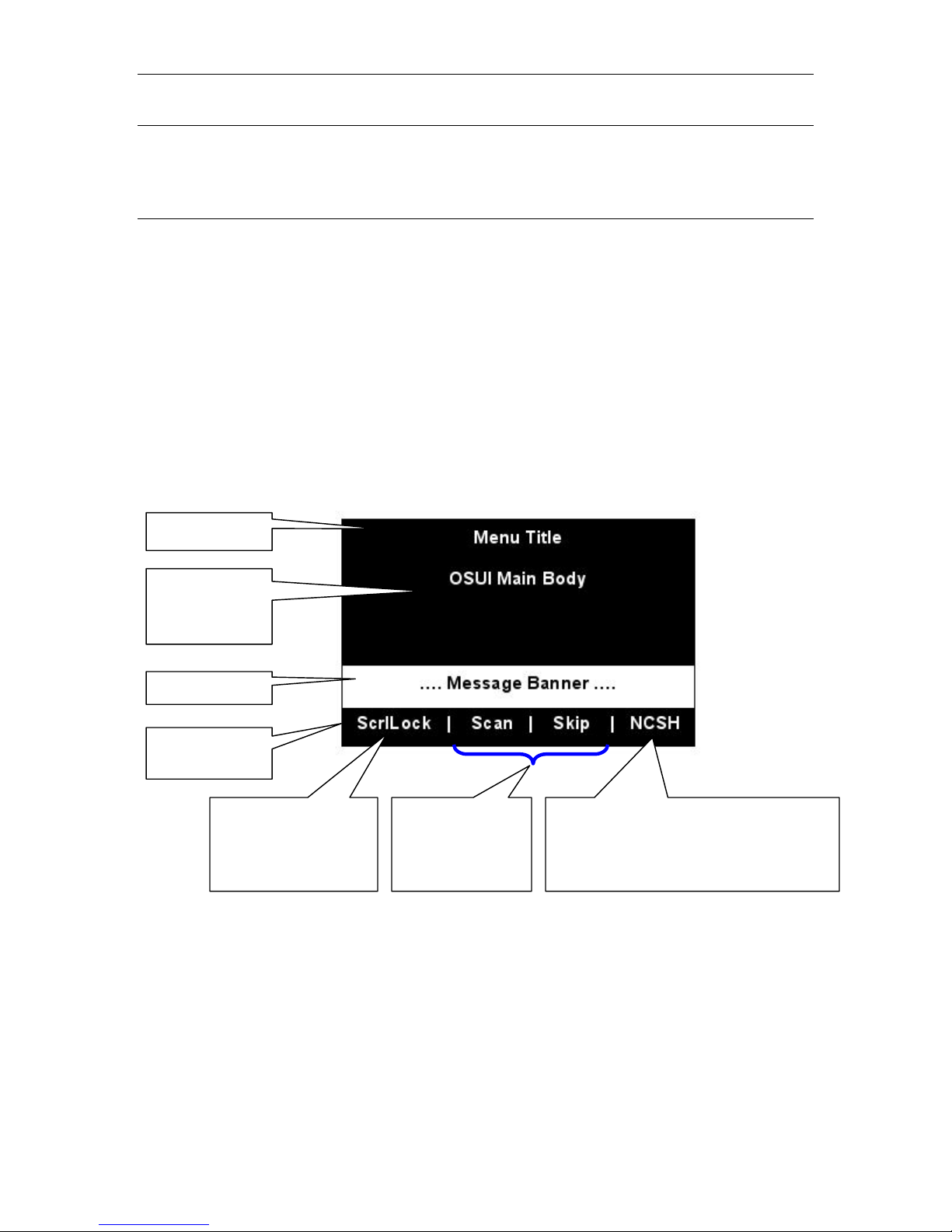
hotkey ([Scroll Lock]) twice on an attached keyboard. Each OSUI menu contains the following sections: a
menu-title line, a menu/screen body (for text and fields), a prompt/message bar, and a status line that
consists of:
• The current OSUI hotkey
• Scan/Skip status
• NCS ([Num Lock], [Caps Lock], and [Scroll Lock]) status indicator
• A communication-speed indicator (“L” for low or “H” for high, which will depend on your Paragon
components) showing the communication speed between the User Station and Base Station.
Title Line
Menu/Screen
Body (for text
and fields)
Messages Banner
Status Line –
displays….
…the current OSUI hot
key activator (in this
case, the [Scroll Lock]
key)
…Scan/Skip status
(if yellow, option is
ON; if white, option
is OFF)
…(N) Num Lock, (C) Caps Lock, (S) Scroll
Lock, followed by P2 Communication Speed
Indicator: (L) Low or (H) High (speed can
depend on your component versions)
Figure 17 Format of OSUI screens
Use function keys [F1], [F2], [F3], [F4], [F8], and [F12] to toggle between first-level menus. Press [F1]
while the OSUI is displayed to activate the Help Menu, a list of available help options. While the OSUI is
on screen, the user-station keyboard’s [Scroll Lock] LED indicator blinks.
CHAPTER 2: INSTALLATION 13
Installing a Paragon System with a Single Base Unit
If installing a single Paragon Base Unit, keep in mind the maximum numbers of user stations and server
CPUs you can connect:
• 2 user stations and 42 CPUs to a P2-UMT242
• 4 user stations and 42 CPUs to a P2-UMT442
• 8 user stations and 32 CPUs to a P2-UMT832M
• 16 user stations and 64 CPUs to a P2-UMT1664M
Important! All Paragon components, CPUs, and monitors must be turned OFF and unplugged
before installation.
1. Initialize the Base Unit.
a. Run the Base Unit’s included power cord from the IEC 320 inlet on its rear panel to a working AC
outlet.
b. Power ON the Base Unit.
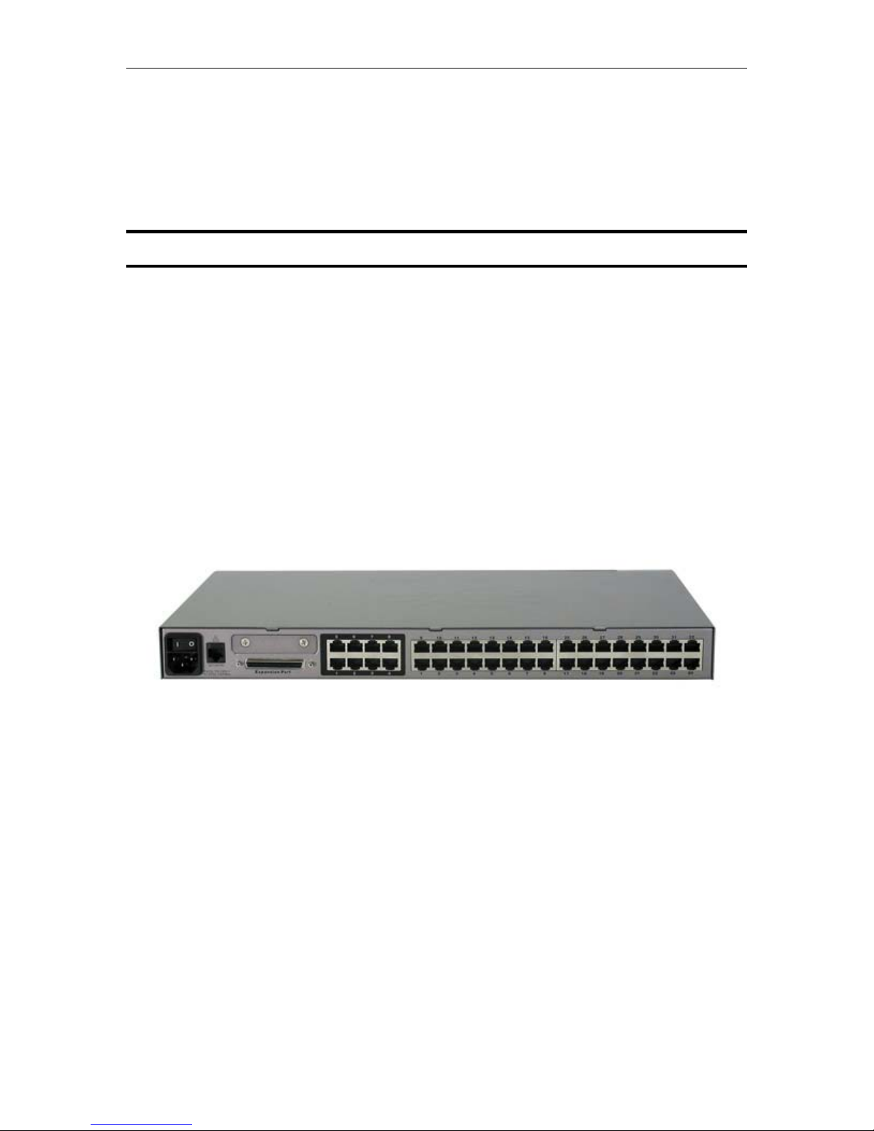
2. Connect a User Station and its attached devices.
a. Connect one end of a CAT5 UTP cable to user port # 1 on the back of the Base Unit. Connect the
other end of the cable to the RJ-45 CAT5 port on the back of the User Station.
b. Run the User Station’s included power cord from the IEC 320 inlet on its rear panel to a working
AC outlet.
c. Power ON the User Station. It will power up and establish communication with the Base Unit.
d. Connect a PS/2 keyboard, PS/2 mouse, and VGA monitor to the User Station. (If there will be any
Sun CPUs in your system, you can connect a Sun keyboard and mouse later, after you have
configured the system for Sun input. To control Sun CPUs with a PS/2 keyboard, please see
Appendix F: Emulating Sun Keys with a PS/2 Keyboard for additional information.)
e. Plug in and power ON the monitor.
Figure 18 Rear panel of a Paragon User Station and
P2-UMT832M unit
14 PARAGON II USER MANUAL
3. Initially configure the User Station.
a. The Login Menu should be displayed on the User Station’s attached monitor. If the [Scroll Lock]
LED on the User Station’s attached keyboard is blinking, the Paragon is ready to accept hotkey
commands, which can be used with the OSUI to login, select servers, or administer the system.
Figure 19 Login Menu for a P2-UMT832M
If the monitor instead displays a “.....No connection to Paragon.....” message, the User Station is not
properly connected to the Base Unit. Check for loose connections and make sure you are using good,
intact CAT5 cables.
b. Type admin in the User Name field and press the [Enter] key. In the Password field, type the
default password raritan (all lowercase) and press the [Enter] key.
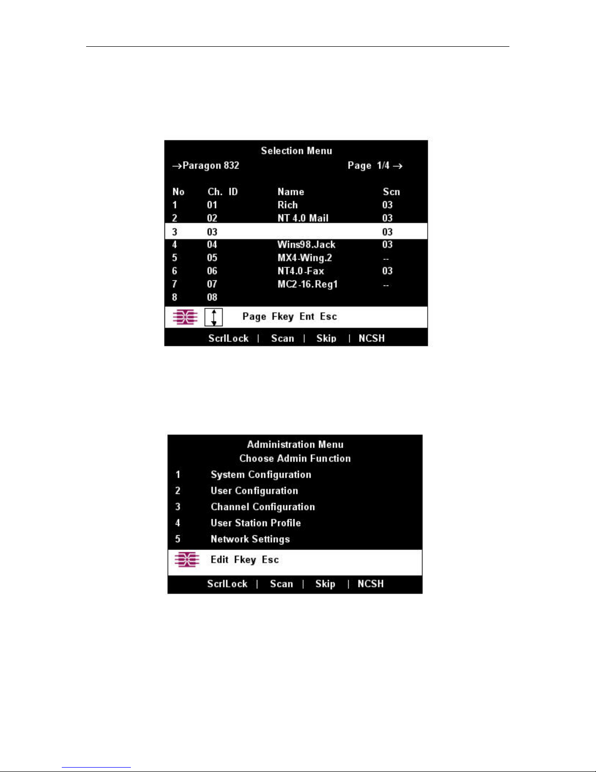
c. The OSUI’s Selection Menu will appear, indicating that the User Station is correctly installed.
4. Repeat steps 2 and 3 for each User Station you want to connect to the Base Unit.
Figure 20 Selection Menu for a P2-UMT832M
CHAPTER 2: INSTALLATION 15
5. Connect a P2CIM-PS2 and its server CPU.
a. Connect the cable strands of an appropriate P2CIM-PS2 to the desired ports on a server CPU:
i. P2CIM-PS2 (IBM PS/2 compatible CPUs): Plug the HD15 strand into the CPU’s HD15 VGA
video port. Plug the purple 6-pin mini-DIN keyboard strand into the CPU’s 6-pin mini-DIN
keyboard port. Plug the light green 6-pin mini-DIN strand into the CPU’s 6-pin mini-DIN
mouse port.
ii. P2CIM-SUN (Sun compatible CPUs): Plug the HD15 strand into the CPU’s HD15 VGA
video port. Plug the 8-pin mini-DIN strand into the CPU’s 8-pin mini-DIN keyboard/mouse
port.
iii. P2CIM-USB (USB CPUs of any platform or P2 CIM-SUSB): Plug the HD15 strand into the
CPU’s HD15 VGA video port. Plug the USB Type A strand into one of the CPU’s USB Type
A ports.
iv. AUATC (serial CPUs, routers, etc.): Please see Appendix E: Using AUATC for RS-232
Access for installation instructions.
v. Z-CIM (local [single-user] IBM PS/2 compatible CPUs): Please see Chapter 5: Paragon II
and Z-CIM for installation instructions.
b. Plug in and power ON the CPU. If the P2CIM-PS2 is installed and operating properly, the
P2CIM-PS2’s green LED will start blinking: once per second while the P2CIM-PS2 is idle, more
quickly while data is passed in either direction.
c. Connect one end of a CAT5 UTP cable to RJ-45 port #1 on the back of the Base Unit. Connect the
other end of cable to the RJ-45 port on the P2CIM-PS2.
6. Configure the P2CIM-PS2 and the attached CPU.
a. The monitor attached to the User Station will display the Selection Menu; with the CPU you just
connected displayed in green. Use the up- and down-arrow keys to move the highlight to that entry
and press the [Enter] key. If you can access and operate the CPU normally, the P2CIM-PS2 is
connected successfully. Raritan recommends you give the server a meaningful system name at this
time, as described in the next steps.
Note: If your video image is fuzzy (especially if you are using an LCD flat-panel monitor), you can adjust
the video gain to focus the video image. If the OSUI is not already displayed, activate it by pressing the
[Scroll Lock] key twice rapidly, then use the numeric keypad’s [+] and [–] (plus and minus) keys to adjust
the video image until it appears to be in focus.
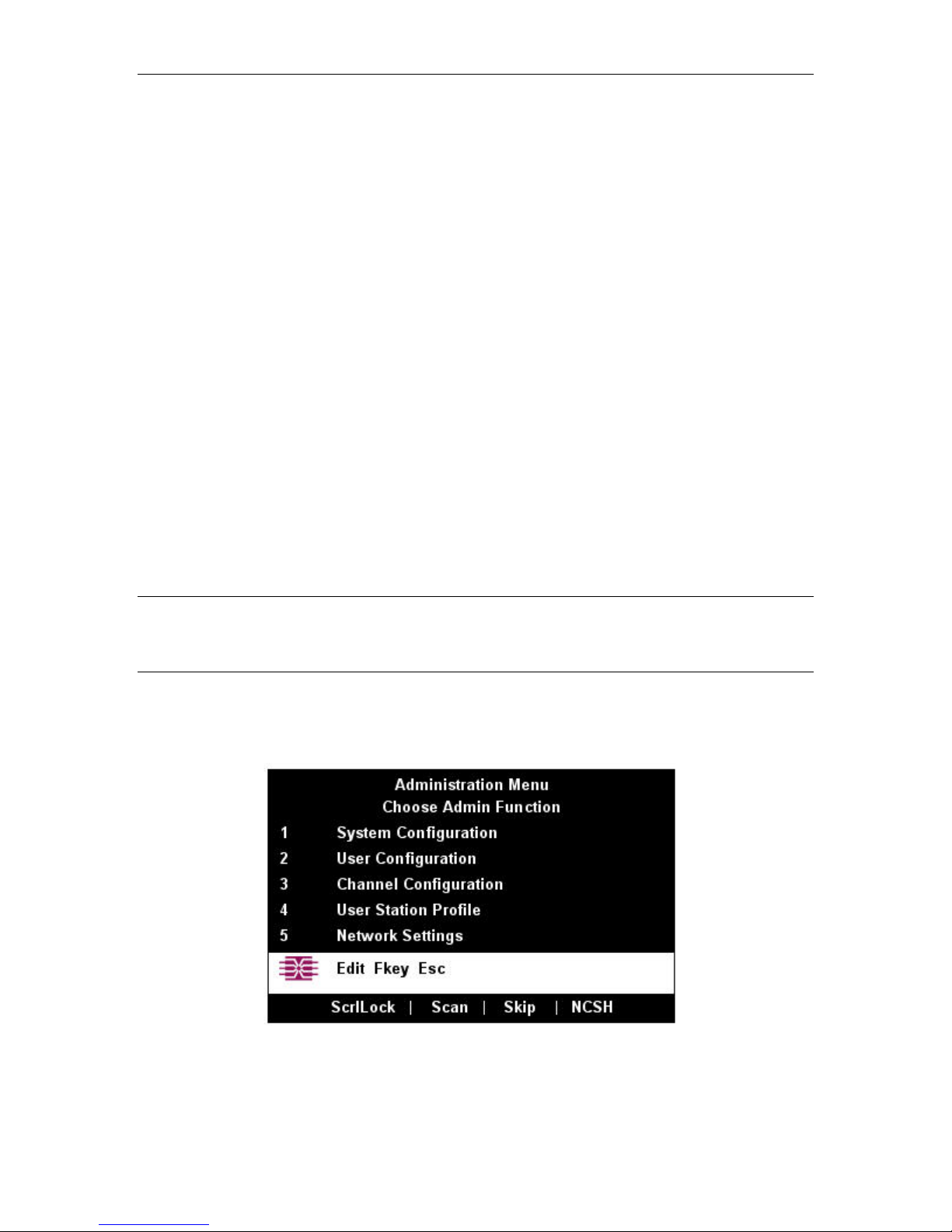
b. Press [F5] to activate the Administration Menu. Use the up- and down-arrow keys to move the
highlight to the Port Configuration entry and press the [Enter] key to select it.
Figure 21 Administration Menu
16 PARAGON II USER MANUAL
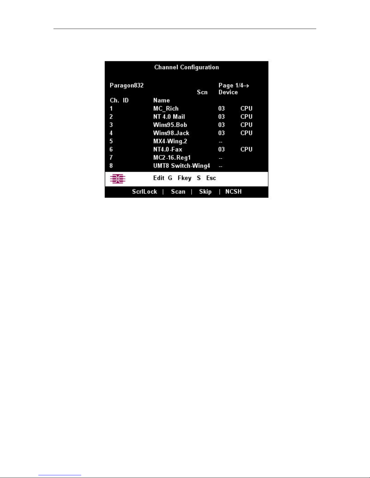
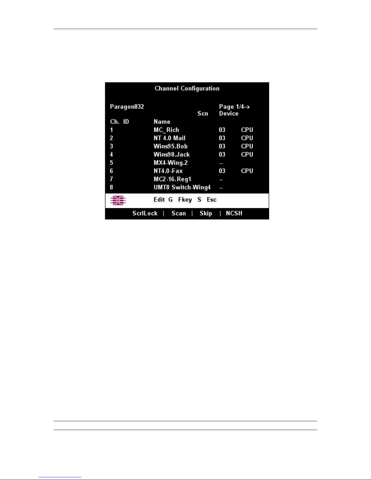
c. The Channel Configuration menu will appear. Use the up- and down-arrow keys to move the
yellow highlight to the Name field for the channel port number where you installed the CPU and
press the [Enter] key. The highlight should turn light blue.
Figure 22 Channel Configuration Menu of a P2-UMT832M
d. Edit the name (it should turn green when you start typing). Press the [Enter] key when you finish,
and then press [S] to save the new name.
e. Press the [Enter] key to return to the Selection Menu. Verify that the new name appears in the
Selection Menu in green.
7. Repeat steps 5 and 6 for each P2CIM-PS2 and CPU you want to connect to the Base Unit’s channel
ports.
CHAPTER 2: INSTALLATION 17
Installing a Cascaded Paragon System
Paragon II’s channel port capacity can be expanded by installing a cascade of Base Units. In a “two-tiered”
cascaded system, one or more subsidiary Base Units are connected to the channel ports of a master Base
Unit. If you fully populate a second tier, you can add a third tier by connecting additional subsidiary Base
Units to the channel ports of Base Units in the second tier. Three tiers is the maximum depth of a cascaded
system; only CIMs may be attached to the channel ports of Base Units in the third tier. A three-tier system
can accommodate up to 2048 CPUs.
Note: In cascaded configurations, the subsidiary Base Units in the third tier (if there is one) must be
powered ON first, then the subsidiary Base Units in the second tier, then the master Base Unit. User
Stations can be powered ON and OFF at any time as needed.
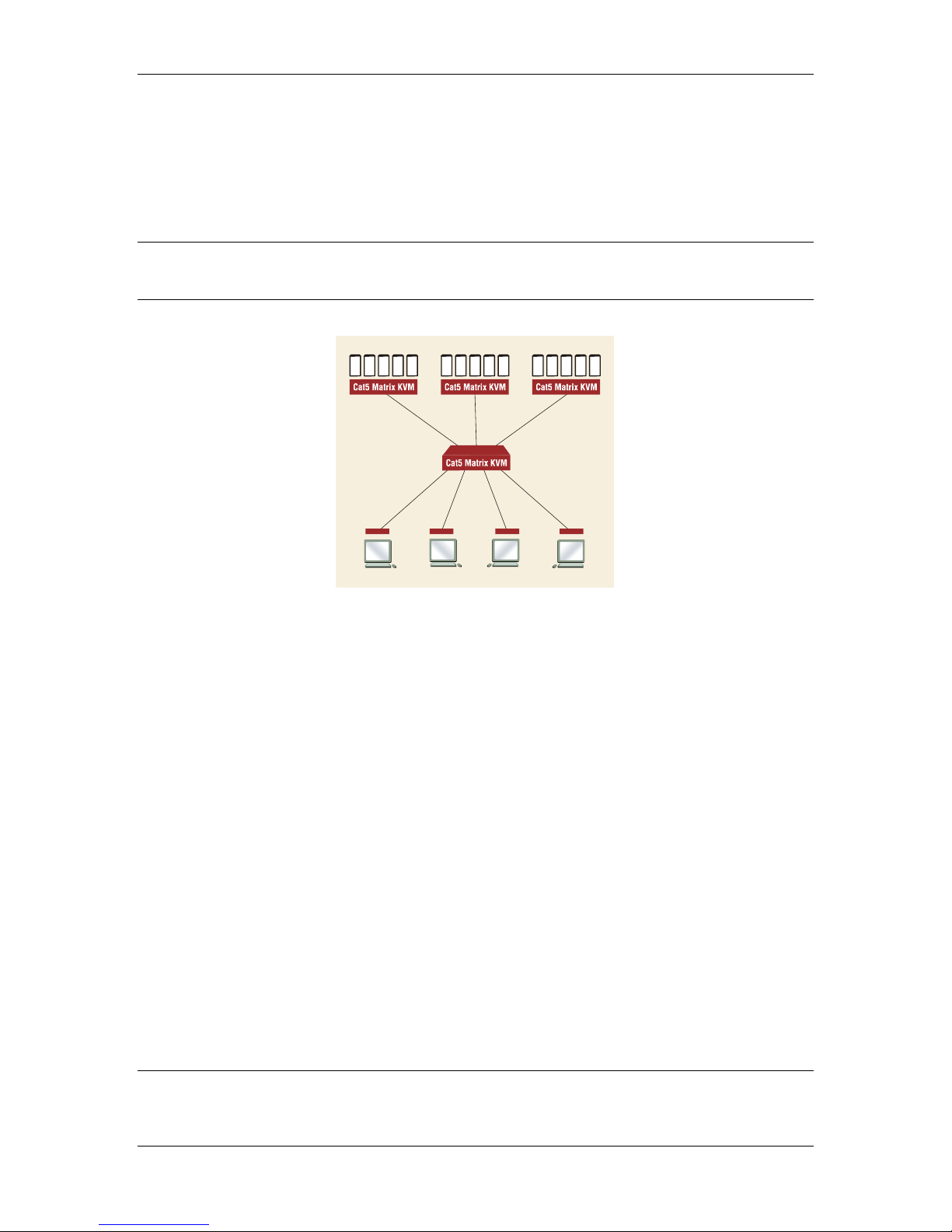
Figure 23 Sample cascaded system
1. Connect one end of a CAT5 UTP cable to user port #1 on the back of the master Base Unit. Connect
the other end of the cable to the RJ-45 CAT5 port on the back of the User Station. Connect a PS/2
keyboard, PS/2 mouse, and VGA monitor to the User Station. Do not plug in or turn on the User
Stations or monitors yet. (Do not attach anything to the Base Unit’s channel ports and do not plug it in
or turn it on yet.)
2. For each subsidiary Base Unit you want to attach directly to the master, run CAT5 UTP cables from
consecutive channel ports on the master Base Unit to the subsidiary Base Unit’s user ports.
3. If you are installing a third tier: Run CAT5 UTP cables from consecutive channel ports on a secondtier Base Unit to the user ports on a third-tier Base Unit. Repeat for all other subsidiary Base Units in
the third tier.
4. Follow step 5 of Installing a Paragon System with a Single Base Unit to attach CIMs and CPUs to
the channel ports of any third-tier Base Units, any free channel ports on your second-tier Base Units,
and any free channel ports on your master Base Unit.
5. Following step 1 of Installing a Paragon System with a Single Base Unit, plug in and power ON any
third-tier Base Units, then plug in and power ON second-tier Base Units, then plug in and power ON
your master Base Unit. Following steps 2b, 2c, and 2e of Installing a Paragon System with a Single
Base Unit, plug in and power ON your User Stations and monitors. The master Base Unit should
automatically recognize the connected subsidiary Base Units and update its configuration. All monitors
should display the Login Menu. If any monitors instead display a “.....No connection to Paragon.....”
message, the User Station they are attached to is not properly connected to the master Base Unit.
Check for loose connections and make sure you are using good, intact CAT5 cables. (See Appendix A:
Specifications for UTP-cabling information.)
Note: If your video image is fuzzy (especially if you are using an LCD flat-panel monitor), you can adjust
the video gain to focus the video image. If the OSUI is not already on screen at a given monitor, activate it
by pressing the [Scroll Lock] key twice rapidly, then use the numeric keypad’s [+] and [–] (plus and minus)
keys to adjust the video image until it appears to be in focus.
18 PARAGON II USER MANUAL
6. Configure the channel ports in your system. (Check the [Scroll Lock] LED on one of your user-station
keyboards. If it is blinking, the Paragon is ready to accept hotkey commands from that user station.
Hotkey commands can be used with the OSUI to login, select servers, or administer the system.)
a. At the Login Menu, type admin in the User Name field and press the [Enter] key. In the
Password field, type the default password raritan (all lowercase) and press the [Enter] key.
b. The monitor will display the Selection Menu, indicating that the User Station is correctly installed.
Figure 24 Selection Menu
c. Press [F5] to activate the Administration Menu. Use the up- and down-arrow keys to move the
highlight to the Channel Configuration entry and press the [Enter] key to select it.
Figure 25 Administration Menu
CHAPTER 2: INSTALLATION 19
d. The Channel Configuration menu will appear. Use the up- and down-arrow keys and [PageUp]
and [PageDown] keys to approach channel ports to which subsidiary Base Units are connected.
These will be shown in white with their default device names in the Name column and their types
in the Device column: “P242” for a 2 x 42 Base Unit (P2-UMT242), “P442” for a 4 x 42 Base
Unit (P2-UMT442), “P832” for an 8 x 32 Base Unit (P2-UMT832M), or “P1664” for a 16 x 64
Base Unit (P2-UMT1664M).
Figure 26 Channel Configuration Menu for a P2-UMT832M
e. Continue using the up- and down-arrow keys and [PageUp] and [PageDown] keys to move the
yellow highlight to the Name field for the channel port number where a subsidiary Base Unit is
installed and press the [Enter] key. The highlight should turn light blue.
f. Type in the name you want to assign to the subsidiary Base Unit on this channel port (the
highlight should turn green when you start typing). Press the [Enter] key when finished, and then
press [S] to save the new name. All other paths (channel ports) by which that subsidiary Base Unit
is attached to the Base Unit above it will be given the same name automatically.
g. Press [F2] to reopen the Selection Menu; make sure that the channel port(s) of the second-tier
Base Unit are properly established. All paths to that Base Unit should be displayed in purple.
h. Press [F5] to return to the Administration Menu. Select Channel Configuration again. Select a
channel port that has been configured for the subsidiary Base Unit you just set up. Press [G] to
activate a dedicated Channel Configuration menu for the subsidiary Base Unit.
i. Edit the names of all server CPUs attached to this subsidiary Base Unit. Each highlight should turn
green as you start typing. Press the [Enter] key when finished with each name. Press [S] to save
all of the new names.
j. Press the [Enter] key to access the dedicated Selection Menu for that subsidiary Base Unit. Verify
that new names appear in the Selection Menu in green.
k. If you are configuring a second-tier subsidiary Base Unit, and there are any third-tier Base Units
attached to it, repeat steps c through j for a third-tier path. Press [S] to save the configuration.
Press [F2] to activate the third-tier Selection menu and verify that the third-tier Base Unit is
properly configured: Select a channel port for the second-tier path and press the [Enter] key, then
a channel port for the third-tier path and press the [Enter] key, then a channel port for a CPU
attached to the third-tier Base Unit and press the [Enter] key. If you can properly access and
operate the chosen CPU, the third-tier Base Unit is properly installed.
Note: Repeat step k for all remaining third-tier Base Units (if any) attached to this second-tier Base Unit.
l. Press [S] to save the configuration. Press [F2] to activate the Selection menu and verify that the
second-tier Base Unit is properly configured: Select a channel port for the second-tier path and
 Loading...