

Raritan ICER-ETTE 84, ICER-ETTE 85 Installation, Operation, Maintenance And Troubleshooting Manual
Page 1
ICER-ETTE™
MODEL 84 and 85 AUTOMATIC ICE CUBE MAKER
INSTALLATION, OPERATION, MAINTENANCE AND TROUBLESHOOTING
WARNING: Raritan Engineering Company, Inc. recommends that a qualified technician install, troubleshoot
and repair this product. Equipment damage, injury to personnel or death could result from
improper installation. Raritan Engineering Company, Inc. accepts no responsibility or liability
from damage to equipment, or injury or death to personnel that may result from improper
installation of this product.
WARNING: Refrigeration Equipment contains refrigerant fluids under very HIGH PRESSURE. Danger of
sudden pressure release may cause injury, death or severe frostbite resulting from not following
instructions.
CAUTIONS:DO NOT plug a 120 volt unit into a 240 volt power source.
DO NOT plug a 240 volt unit into a 120 volt power source.
DO NOT use a transformer to step down 240 volt 50 HZ power supply to 120 volt.
Equipment designed for 60 HZ may run slow on 50 HZ, resulting in inferior operation and possible
overheating of the motor(s).
WARNING: This device is not ignition protected. DO NOT install in compartments containing gasoline tanks
or in areas in which
ignition protected equipment is required.
INTRODUCTION
Series 84 and 85 Icer-ettes are CFC-Free automatic
icemakers designed and manufactured especially for
the marine environment. They produce up to 22 lbs
(10kg) of crescent shaped ice per day and can store 11
lbs (5kg). Two cabinet configurations are offered,
allowing counter height installations and shorter
limited height installations. Installation and
maintenance are simple because no drain is required
and the thermostat is fixed; never needing adjustment.
OPERATION
The Icer-ette's on-off switch is just beneath the door.
A unit begins to produce ice within 60 minutes after
start-up. Ice production stops automatically when
the bucket is full enough to interfere with the wire
shut-off arm. The unit should not be turned "off" with
the door closed and ice or water inside.
NOTES:
1. Due to fast freezing, ice cubes may appear
"cloudy". This is trapped air in the water and
does not affect the taste or quality of the ice.
2. "Hollow" ice cubes may result from fastfreezing under certain climatic conditions such
as high humidity, etc. and is not an indication
of a problem with the icemaker.
MAINTENANCE
Periodically vacuum dust and dirt from the condenser,
located behind louvered grill at the bottom front of
the unit; taking care not to damage aluminum fins in
the process. Regularly inspect plumbing connections
to insure that no leaks are present.
When necessary, defrost and thoroughly clean the
inside of the unit with mild soap and water. Do not
use electrical heating devices, sharp or pointed tools
when defrosting. When defrosting or leaving the unit
turned off, prop and leave the door open using door
lock link. This allows air to dry the inside of the
cabinet, reducing the chance for mildew and damage
to the mold mechanism's components.
WINTERIZING
WARNING: Disconnect power at source before
working on the unit. Do not winterize this unit
with ANY type of anti-freeze; damage to the mold
coating will occur, invalidating product's Limited
Warranty and creating potential health hazard.
1. Shut off the water supply to the unit.
2. Disconnect as follows:
Model 85: Disconnect water supply connector behind
front grille at solenoid valve (garden hose connector).
Remove white plastic tubing and nut from bottom of
solenoid valve.
Model 84: Disconnect the in-line water supply
connector behind the front grille.
3. Turn power on. Allow unit to run for an hour.
Remove any cubes that may have been ejected
1
Page 2
during this period. Turn off power and prop door
open to allow the inside to defrost. After it has
defrosted, wipe it dry and leave door open using
door lock link.
RECOMMISSIONING
Connect water supply lines, turn on water, check for
leaks, then restore power to the unit. After initial cool
down of 45-60 minutes, the unit will cycle
approximately every 40 minutes.
MOUNTING
WARNING: If rubber feet are removed from the
bottom of 85 series units, the mounting screws
must be reinstalled into the bottom of the cabinet
to avoid damage to components mounted to the
base pan.
If unit is to be built-in, 3/4" (2cm) or more must be
allowed behind the unit for water line and plug
clearance for proper operation. Built-in units are
designed for zero clearance at the top and each side
of the unit. Fan-forced condenser cooling is used.
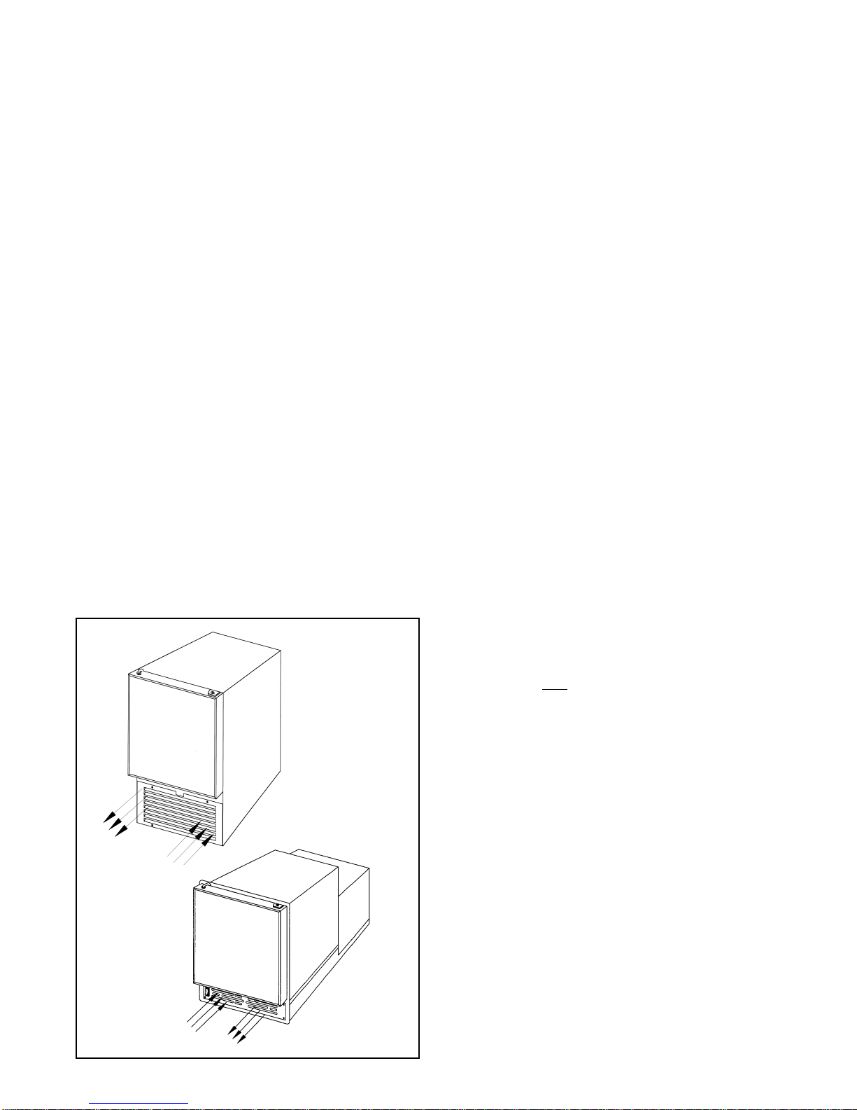
This requires air circulation through lower section of
unit (see Fig. #1). If Icer-ette is to be installed behind
closed doors, contact Raritan Technical Support.
CAUTION: Any restriction of airflow or
ventilation will disrupt normal operation of the
unit, resulting in damage to components and voids
warranty.
FIG. #1 Ventilation
Model 85
Unit must sit on a secure level surface. Mounting
flange must NOT be used to support the unit's weight.
When installing the unit it should be noted that some
servicing requires access to the rear of the unit and
that the unit must be readily removable should
servicing be necessary.
When mounting unit within cabinetry, make sure
that the door has the desired range of motion. All
doors are hinged on the right (facing the unit) but may
be reversed in the field.
PLUMBING
A minimum of 22 P.S.I. (152kPa) is required for
proper operation of the water valve (see #27, page 4).
When plumbing the Model 85 remove front grille.
Run a 1/4" O.D. water line through the rear of the
cabinet (hole provided) and attach to the garden hose
adapter on the solenoid water valve. Replace front
grille.
When plumbing the Model 84, 18" (45cm) of water
line extends from the back with a 1/4" plastic female
compression fitting. Drains are not required; just a
water supply.
WIRING
WARNING: HAZARD OF ELECTRIC SHOCK
- Never use extension cords or plug adapters to
power unit. Never remove the ground prong from
the plug.
Power Requirements: 120 volts 60 HZ AC
(alternating current); a three-wire cord with grounded
plug is supplied,
OR: 240 volts 50 HZ AC (alternating
current), supplied with Euro-plug.
OUT
IN
IN
OUT
Air path for exhaust
and fresh air intake
must be unrestricted!
Recirculation between
fresh air intake and
exhaust air must be
prevented.
Model 84
START-UP
Turn on water, check for leaks and then turn on
power. Turn on switch (located just below Icer-ette
door). Fan and compressor will normally turn on
immediately, resulting in air circulation through the
grille and a faint hum from the compressor. If
machine was shut off while in ice harvesting cycle, it
will have to complete the cycle before compressor
and fan turn on (approximately 5 minutes). Interior
temperature will drop below freezing. First harvest
of ice should occur within 60 minutes of start-up.
After lines are purged of air, normal harvesting and
refilling occur every 40 minutes or less, under normal
conditions.
2
Page 3
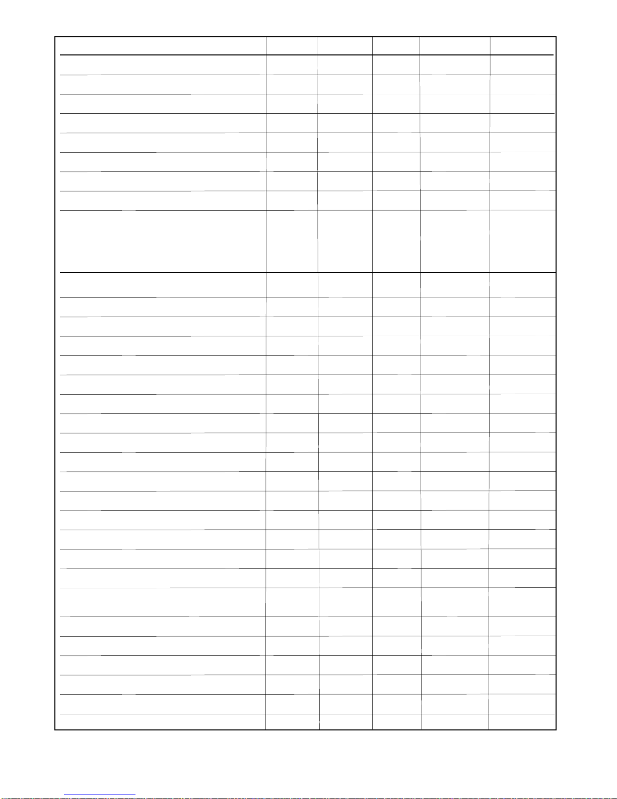
Item Description Part # Mod. 84 84 240V Mod. 85 85 240V
1 Wiring Harness I44W I44W220 I44 I44220
2 Module Assembly (628366) I34M-1 I34M220 I34M-1 I34M220
3 Thermostat I34T I34T I34T I34T
4 Ice Maker Mold w/ Heating Element I34MH I34MH220 I34MH I34MH220
11 Door Lock Link I19B I19B I19B I19B
12 Door Retainer Bracket I17 I17 I17 I17
13 Link Retaining Ring 1306 1306 1306 1306
14 Nylon Snap Bushing I21 I21 I21 I21
15 S/S Door Assy. I7W I7W I7W I7W
White Laminate Door Assy I61W I61W I61W I61W
Black Laminate Door Assy. I701W I701W I701W I701W
Neutral White Laminate Door Assy. I610W I610W I610W I610W
Antique White Lamiante Door Assy. I611W I611W I610W I610W
16 On-Off Rocker Switch I37S I37S I37 I37
17 8-32 x 1/2 Hex Head Type F 18-8 S/S Screws F088 F088 F088 F088
18 Grille I9S I9S I9 I9
19 1/4 -20 x 1/2 RH S/S Screw 1124 1124 1124 1124
20 Hinge Set (Top & Bottom) I12 I12 I12 I1 2
21 Ice Bucket I90 I90 I90 I90
22 Ice Maker I34W I34220W I34W I34220W
23 Ice Maker Front Cover I34A I34A I34A I34A
24 Relay w/ overload protector I1806-1 I1806-2 I1806-1 I1806-2
25 Water line Tubing I93SW I93SW I93W I93W
26 Condenser Coil I24S I24S I24 I24
27 Water Valve I34B I34B220 I34B I34B220
28 Compressor (Includes #33 and #40) II800A-1W I1800A-2W I1800A-1W I1800A-2W
29 Power Cord I41 I41220 I41 I41220
30 Rear Panel I11S I11S I1 1 I11
31 Back Enclosure Cover I20A I20A N/A N/A
32 Flange I99S I99S I99 I99
Flange with Holes I99H I99H
33 Service Valve w/ Tube I101 I101 I101 I101
40 Drier I30A01 I30A01 I30A01 I30A01
41 Motor and/or Blower Assembly I28 I28220 I25 I25220
42 Cold Control I33 I33 I33 I33
43 Relay I52 I52220 I52 I52220
44. Air Duct I29 I29 N/A N/A
(Motor/Blower Assembly)
3
(Fan Motor Only-I27 Fan blades not included)
Page 4
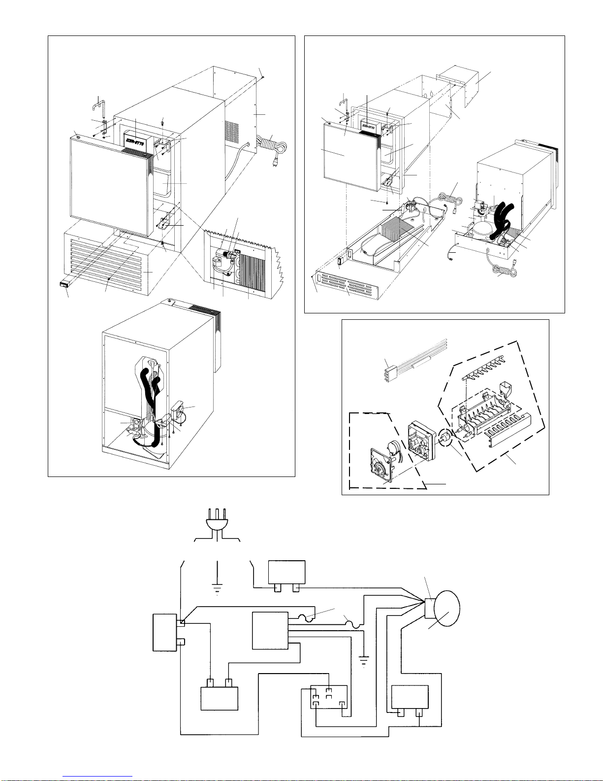
Exploded View of Model 85 Icer-ette
Exploded View of Model 84 Icer-ette
16
14
12
11
15
17
13
23
18
22
19
19
20
20
21
24
28
25
33
27
26
17
30
29
15
17
14
11
23
12
19
20
13
22
21
32
27
20
19
40
25
16
18
Exploded view of Item #22
26
24
33
29
25
30
44
41
43
28
29
42
31
27
26
40
41
40
Wiring Diagram
Raritan Icer-ette
Series 84 and 85
43
WHITE
BLUE
COLD CONTROL
WHITE
42
GREEN
GREEN/YELLOW
WHITE
WATER
VALVE
LINE VOLTAGE
BLACK (120 VAC)
BROWN (240 VAC)
POWER
SWITCH
WHITE
ICE
MAKER
MODULE
BROWN
(240 V ONLY)
7
BLACK
LINKS
ORANGE
RELAY
A B
FUSE
2
1
COMPRESSOR RELAY
AND OVERLOAD
BLACK
GREEN
BLACK OR WHITE
3
4
2
COMPRESSOR
FAN
BLACK
WHITE
4
Page 5
TROUBLESHOOTING SECTION
BE SURE TO READ THE FOLLOWING PARAGRAPH BEFORE ATTEMPTING ANY TROUBLESHOOTING OR
REPAIR OF ICER-ETTE UNITS.
WARNING: It is recommended that only a qualified refrigeration technician perform service on Icer-ettes. Because of
high voltage, high pressure refrigeration, and presence of water in the unit, a person who is not technically
qualified may be subject to electric shock hazard. If the Icer-ette is wired to a junction box or otherwise direct
to the AC power supply, the appropriate circuit breaker must be turned off to cut the power to the machine.
TURNING THE ON-OFF SWITCH TO THE “OFF” POSITION DOES NOT DISCONNECT THE UNIT
FROM THE POWER SOURCE AND THE DANGER OF ELECTRIC SHOCK WILL REMAIN.
This Troubleshooting Section is to be used only as a guideline to assist in determining any problem. Raritan does not
guarantee that the recommendations or corrections listed below will correct the problem.
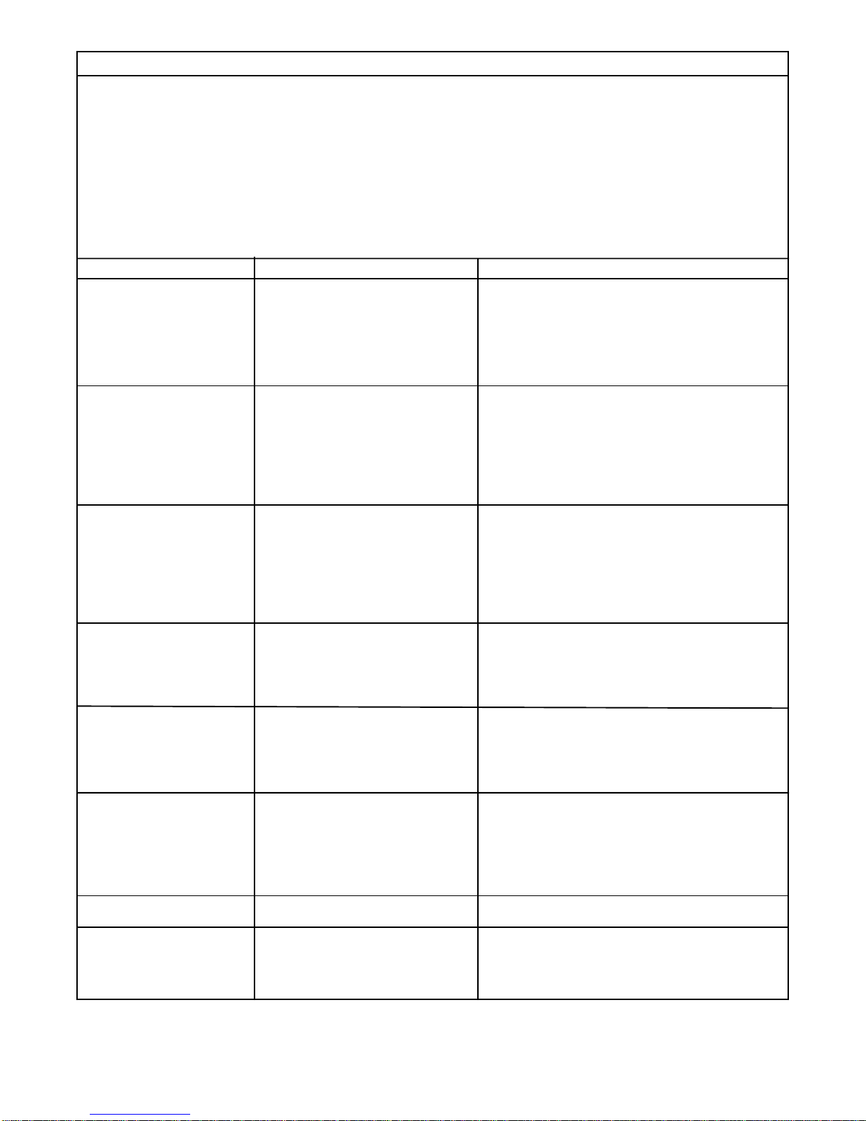
PROBLEM
1.Compressor and fan not running.
2. Icer-ette will not get cold
enough to freeze cubes in
the mold.
3. Icer-ette freezes but water
does not come into mold; no
ice production.
4. Icer-ette will freeze cubes
but will not eject them.
5.Icer-ette stops in mid-ejection cycle; compressor will
not come back on.
6.Icer-ette makes and ejects
cubes but at a very slow
rate.
7.Icer-ette frosts up inside and
has to be defrosted often.
8.Excessive accumulation of
ice; water overflows the ice
mold and runs into storage
bucket; solid block of ice.
1A. No AC power - check breaker.
1B. AC power switch.
1C. Compressor Relay.
1D. Module.
1E. Cold control.
2A. Compressor.
2B. Refrigerant leak in system.
2C. Fan motor.
2D. Dust clogged in condenser.
2E. Jammed fan.
2F. Refer to 1 above.
2G. Module
3A. Nonfunctioning water valve
3B. Mold heater assembly.
3C. Water supply turned off.
3D. Icemaker module.
3E. Cold control.
3F. Bad wiring harness plug contacts.
4A. Ice mold thermostat.
4B. Icemaker module.
4C. Ejector relay.
4D. Mold and heater assembly.
4E. Bad wiring harness plug contacts.
5A. Limit switch in wire harness.
5B. Icemaker module.
5C. Power supply.
5D. Mold and heater assembly.
5E. Bad wiring harness plug contacts.
6A. Ice mold thermostat.
6B. Fan motor.
6C. Ventilation poor.
6D. Dust clogged in condenser.
6E. Too much water in mold.
6F. Ejector relay.
7A. Broken door gasket.
7B. Door left open.
8A. Solenoid valve assembly.
8B. Icemaker module.
8C. Filler tube alignment.
8D. Icemold thermostat.
POSSIBLE CAUSE
assembly.
CORRECTION
1A. Turn on breaker to restore power.
1B. Check for loose connections. Replace switch if
needed.
1C. Replace Compressor Relay.
1D. Replace icemaker module.*
1E. Replace cold control.*
2A. Return to Raritan for compressor replacement.
2B. Contact Raritan Technical Support.
2C. Replace fan motor.*
2D. Clean Condensor (see maintenance section).
2E. Straighten fan brackets.
2F. Refer to 1A, B and C.
2G. Replace icemaker module.*
3A. Clean or replace solenoid valve assembly.
3B. Contact Raritan Technical Support.
3C. Provide pressurized water.
3D. Replace icemaker module.
3E. Replace cold control.
3F. Contact Raritan Technical Support.*
4A. Replace ice mold thermostat.*
4B. Replace icemaker module.*
4C. Replace ejector relay.
4D. Replace icemaker module.*
4E. Contact Raritan Technical Support.*
5A Contact Raritan Technical Support.*
5B. Replace icemaker module.*
5C. Check connections.
5D. Replace icemaker module.
5E. Contact Raritan Technical Support.*
6A. Replace ice mold thermostat.*
6B. Replace fan motor.*
6C. Check installation section.
6D. Clean condensor (see maintenance section).
6E. Contact Raritan Technical Support.
6F. Replace ejector relay.
7A. Replace door gasket.
7B. Defrost as needed.
8A. Replace solenoid valve assembly.
8B. Replace icemaker module.*
8C. Adjust to prevent splash over.
8D. Replace icemold thermostat.*
* See visual aid reference at www.raritaneng.com/tech support/repair shop
NOTE: Model 84 Icemakers must have rear panel part #31 reinstalled before operating or testing unit. Unit will not
operate or test satisfactorily without panel in place.
5
Page 6
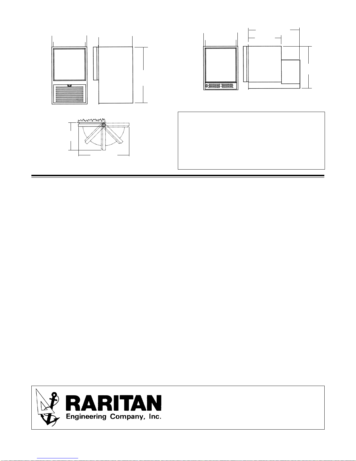
DIMENSIONS:
15 3/8"(39.1cm)flange
14"(35.6cm)
cabinet
14 3/4"
(37.5cm)
Door Swing Models 84 & 85
14 1/2"(36.8cm)
Model 85
27"(68.6cm)
15 3/8"(39.1cm)flange
24"
(61cm)
cabinet
Recess Dimensions HxWxD = 18 1/2"(47cm) x 14 1/2"(36.9cm) x 23"(58.4)
SPECIFICATIONS:
Ice Production: up to 22 lbs. (10kg) per day
Water Supply: Minimum 22 psi (152kPa)
Ice Storage Capacity: up to 11 lbs. (5kg)
Max. AMP Draw: 120 Volt - 2.5; 240 Volt - 1.3
Refrigerant Charge: 2.4 oz. (68 grams) R-134A
LIMITED WARRANTY
14" (35.6cm)
cabinet
Maximum 125 psi (863kPa)
22 1/4"(56.5cm)
14 7/32"
(36.6cm)
18 3/8"
(46.7cm)
Model 84
Raritan Engineering Company warrants to the original purchaser that this product is free of defects in materials or workmanship for a period of one
year from the product’s date of purchase. Should this product prove defective by reason of improper workmanship and/or materials within the
warranty period, Raritan shall, at its sole option, repair or replace the product.
1. TO OBTAIN WARRANTY SERVICE, Consumer must deliver the product prepaid, together with a detailed description of the problem, to Raritan
at 530 Orange St., Millville, N.J. 08332, or 3101 SW 2nd Ave. Ft. Lauderdale, FL 33315. When requesting warranty service, purchaser must
present a sales slip or other document which establishes proof of purchase. THE RETURN OF THE OWNER REGISTRATION CARD IS NOT
A CONDITION PRECEDENT OF WARRANTY COVERAGE. However, please complete and return the owner Registration Card so that Raritan
can contact you should a question of safety arise which could affect you.
2.THIS WARRANTY DOES NOT COVER defects caused by modifications, alterations, repairs or service of this product by anyone other than
Raritan; defects in materials or workmanship supplied by others in the process of installation of this product; defects caused by installation of
this product other than in accordance with the manufacturer’s recommended installation instructions or standard industry procedures; physical
abuse to, or misuse of, this product. This warranty also does not cover damages to equipment caused by fire, flood, external water, excessive
corrosion or Act of God.
3.ANY EXPRESS WARRANTY NOT PROVIDED HEREIN, AND ANY REMEDY FOR BREACH OF CONTRACT WHICH BUT FOR THIS
PROVISION MIGHT ARISE BY IMPLICATION OR OPERATION OF LAW, IS HEREBY EXCLUDED AND DISCLAIMED. ALL IMPLIED
WARRANTIES SUCH AS THOSE OF MERCHANTABILITY AND OF FITNESS FOR A PARTICULAR PURPOSE, IF APPLICABLE, AS
WELL AS ANY IMPLIED WARRANTIES WHICH MIGHT ARISE BY IMPLICATION OF LAW, ARE EXPRESSLY LIMITED TO A TERM
OF ONE YEAR. SOME STATES DO NOT ALLOW LIMITATIONS ON HOW LONG A LIMITED WARRANTY LASTS, SO THE ABOVE
LIMITATION MAY NOT APPLY TO YOU.
4.UNDER NO CIRCUMSTANCES SHALL RARITAN BE LIABLE TO PURCHASER OR ANY OTHER PERSONS FOR ANY SPECIAL OR
CONSEQUENTIAL DAMAGES, WHETHER ARISING OUT OF BREACH OF WARRANTY, BREACH OF CONTRACT , OR OTHERWISE.
SOME STATES DO NOT ALLOW THE EXCLUSION OR LIMITATION OF INCIDENTAL OR CONSEQUENTIAL DAMAGES, SO THE
ABOVE LIMITATION OR EXCLUSION MAY NOT APPLY TO YOU.
5.No other person or entity is authorized to make any express warranty, promise or affirmation of fact or to assume any other liability on behalf of
Raritan in connection with its products except as specifically set forth in this warranty.
6.This warranty gives you specific legal rights, and you may also have other rights which vary from state to state.
SAVE THESE INSTRUCTIONS
Should a problem arise, please feel free to contact Raritan Technical Support at either the Millville, NJ
or Fort Lauderdale, FL office.
L179 0802 wsw Specifications Subject to Change Without Notice Printed in USA
530 Orange Street, P.O. Box 1157, Millville, NJ 08332 USA
Telephone: 856-825-4900 FAX: 856-825-4409
www.raritaneng.com
Southern Office and Plant:
3101 SW Second Avenue, Fort Lauderdale, FL 33315 USA
Telephone: 954-525-0378 FAX: 954-764-4370
6
 Loading...