

Raritan E1 series Quick Setup Manual
CommandCenter Secure
Gateway E1 Models
Quick Setup Guide
Thank you for your purchase of the CommandCenter Secure Gateway, Raritan's management software platform
engineered to consolidate secure access and control of IT devices. This Quick Setup Guide explains how to install and
configure the CommandCenter Secure Gateway.
For additional information on any aspect of the CommandCenter Secure Gateway, see the accompanying online help
accessed from the CommandCenter Secure Gateway or from the CommandCenter Secure Gateway User Guide, which
can be downloaded from the Firmware and Documentation section of Rarita n's website
(http://www.raritan.com/support/firmware-and-documentation/).
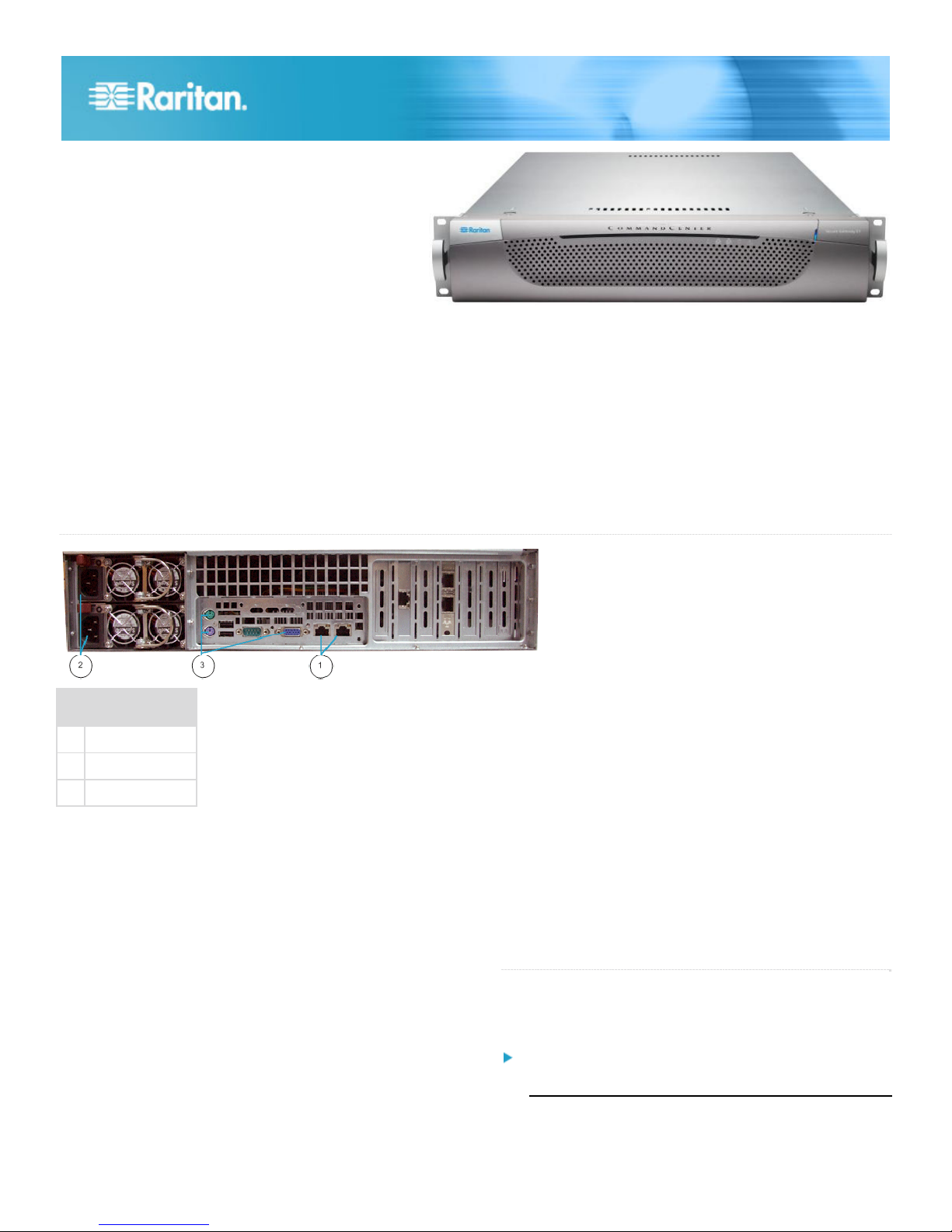
Diagram Key
1 LAN ports
2 Power
3 KVM ports
I. Unpack CC-SG
With your shipment, you should receive:
(1) CommandCenter Secure Gateway E1 unit
(1) CommandCenter Secure Gateway E1 front bezel
(1) Rack mount kit
(2) Power supply cord
(1) CAT 5 network cable
(1) Printed Quick Setup Guide
(1) Registration and Warranty papers
Determine Rack Location
Decide on a location in the rack for CC-SG, in a clean, dustfree, well-ventilated area. Avoid areas where heat, electrical
noise, and electromagnetic fields are generated and place it
near a grounded power outlet.
QS Rule
II. Rack-mount CC-SG
Before rack-mounting CC-SG, unplug all power cords and
remove all external cables and devices.
The rack mount kit contains:
• 2 pairs of rack rails
Each pair consists of two sections: an inner rail that
attaches to the CC-SG unit, and an outer rail that
CC-SG E1 Quick Setup Guide 1
QSG-CCE1-0G-v5.0.0-E y 255-80-5400-01-RoHS
attaches to the rack. A sliding rail guide is positioned
between the inner and outer rails. The sliding rail guide
should remain attached to the outer rail.
• 1 pair of short front brackets
• 1 pair of long rear brackets
• Short screws, Long screws
• Washers
Install Inner Rails onto CC-SG Unit
1. Slide the inner rail out from the outer rail as far as it will
go. Press the locking tab to release the inner rail from the
outer rail and then pull the inner rail completely out. Do
this for both pairs of rack rails.
2. There are five holes on each inner rail that correspond to
the five rail hooks on each side of the CC-SG unit. Align
each inner rail's holes with the rail hooks, and then press
each rail against the unit to attach it.
3. Slide each rail toward the front of the unit until you hear a
click.
4. Attach the inner rails to the CC-SG unit with short screws.
Install Outer Rails onto Rack
1. The outer rails attach to the rack. The outer rails will fit
racks that are 28-32 inches deep.
2. Attach the short front brackets to each outer rail with short
screws. Note the up/Front indication on the brackets when
attaching them.
3. Slide each long rear bracket into the opposite end of each
outer rail. Attach the long rear brackets to the outer rails
with short screws. Note the up/Rear indication on the
brackets when attaching them.
4. Adjust the entire rail unit length to fit the rack depth.
5. Attach each bracketed end of the outer rail to the rack with
washers and long screws.
Install CC-SG into the Rack
Once the rails are attached to both the CC-SG unit and the
rack, install CC-SG into the rack.
1. Fully extend the rack rails, and then line up the rear of the
inner rails with the front of the rack rails.
2. Slide the CC-SG unit into the rack until you hear a click.
You may have to depress the locking tabs when inserting
the CC-SG unit into the rack.
1. Connect the CAT 5 network LAN cable to the LAN 1 port
on the rear panel of the CC-SG unit. It is strongly
recommended to connect a second CAT 5 network LAN
cable to the LAN 2 port. Connect the other end of each
CAT 5 cable to the network.
2. Attach the 2 included AC power cords to the power ports
on the rear panel of the CC-SG unit. Plug the other ends
of the AC power cords into independent UPS protected
outlets.
3. Connect KVM cables to the corresponding ports on the
rear panel of the CC-SG unit.
QS Rule
IV. Log in to Local Console to Set CC-SG IP
Address
1. Power ON CC-SG by pressing the POWER button on the
front of the CC-SG unit.
2. Attach the front bezel by snapping it onto the front of the
CC-SG unit.
3. Log in as admin/raritan. Usernames and passwords are
case-sensitive.
4. You will be prompted to change the local console
password.
a. Type the default password (raritan) again.
b. Type and then confirm the new password. Note the
new password must be a strong password consisting
of at least eight characters that are a combination of
letters and numbers.
5. Press CTRL+X when you see the Welcome screen.
6. Choose Operation > Network Interfaces > Network
Interface Config. The Administrator Console appears.
7. In the Configuration field, select DHCP or Static. If you
select Static, type a static IP address. If needed, specify
DNS servers, netmask, and gateway address.
8. Select Save. Wait a few minutes as CC-SG restarts.
Default CC-SG Settings
IP Address: 192.168.0.192
Subnet Mask: 255.255.255.0
Username/Password: admin/raritan
QS Rule
Locking Tabs Information
Both inner rails have a locking tab:
• To lock the CC-SG unit into place when pushed fully into
the rack.
• To lock the CC-SG unit into place when extended from the
rack.
QS Rule
III. Connect Cables
Once the CC-SG unit is installed into the rack, you can
connect cables. See the diagrams on page 1.
CC-SG E1 Quick Setup Guide 2
QSG-CCE1-0G-v5.0.0-E y 255-80-5400-01-RoHS
 Loading...