

Page 1

smart mini servo feed
cut-to-length
oPerating instructions
MODELS
SMS2, SMS4, SMS8
RAPID-AIR CORPORATION
4601 KISHWAUKEE ST. • ROCKFORD, IL 61109-2925
Phone: (815) 397-2578 • Fax: (815) 398-3887 • Web Site: www.rapidair.com
1
Page 2

table of contents
INTRODUCTION, INSTALLATION AND SET-UP ..................................................................................... pg. 3
ADJUSTMENT, CABLING AND INTERFACING ...................................................................................... pg. 4
PRETEST WITHOUT MATERIAL AND LOADING MATERIAL ................................................................ pg. 5
TROUBLESHOOTING .................................................................................................................................. pg. 6-7
MAINTENANCE PROCEDURES, PRECAUTIONS AND SAFETY ........................................................... pg. 7
CUTTER MAINTENANCE ........................................................................................................................... pg. 8
FSC8/SMS8 CONTROL ASSEMBLY .......................................................................................................... pg. 9
RSC14/SMS2 SERVO CONTROL ASSEMBLY .......................................................................................... pg. 10
PROGRAMMING PROCEDURE ................................................................................................................. pg. 11-13
TROUBLESHOOTING .................................................................................................................................. pg. 14-15
LED STATUS SYMBOLS ............................................................................................................................. pg. 16-18
SMS - CTL FEED DIAGRAM ....................................................................................................................... pg. 19
SMS - CTL SERVO FEED DIAGRAM ......................................................................................................... pg. 20
SMS WITH CUTTER CONTROL PANEL ASSEMBLY .............................................................................. pg. 21
SMS WITH CUTTER WIRING SCHEMATIC ............................................................................................. pg. 22
WARRANTY ................................................................................................................................................. pg. 23
2
Page 3

introduction, installation and set-uP
Smart Mini Servo Feed With Cut-To-Length Introduction
The Rapid-Air Servo Cut-To-Length
Feed system carries with it the
quality and reliability you have grown
to expect from a Rapid-Air product.
The motion control system is a
programmable industrial computer
and this advanced technology,
combined with a highly engineered
precision roll feed, is an unchallenged
combination in the press industry.
The compact mechanical package,
direct coupled with a brushless servo
drive motor, offers response and feed
speed accuracy unparalleled in any
other powered roll feed. Operator
interface is so simplified, a typical
setup person can have the servo
feed programmed and running in a
matter of minutes. A step by step
prompt appears on a four line
80-character display, which asks
simple questions of the operator.
Entry of feed length, cutter dwell time,
and % maximum speed are all that is
required for a new setup. Routine jobs
can be stored, recalled, changed and
saved or run with a simple 2 digit job
number entry. Up to 99 jobs may be
stored and recalled at will.
A resolver, direct coupled to the
servo drive motor for precise digital
position feedback, enable roll
positioning accuracy to +/- .0025 for
any programmed feed length or speed.
Operator programmed feed length,
up to 99.999 inches and % max speed
selection along with full jog features
on a pendant unit, allow the operator
to thread the material and inch it into
position. The inch feature enables the
operator to jog the servo feed forward
or reverse at a slow rate. The operator
can select jog to length or jog continuous to aid in threading up material.
The Rapid-Air Servo Roll Feed has
been designed to mount on a
free-standing table as close as
possible to the cutter.
The precision mechanical roll
feed unit has been designed for
compactness, ease of setup and
installation. Three cables with twist
lock connectors, two cables for the
servo, one connected to the cutter,
and one air line are the only external
connections required. The electrical
controls are housed in a small cabinet
which should be mounted close to
the press working area. The operator
keypad and display are mounted on
top of the control cabinet.
Installation And Mechanical Setup Of Servo And Cutter
If you purchased the servo/cutter
combination already mounted on a
base then the servo and cutter were
aligned at the factory. A good
practice is to check all hold down
bolts to be sure that they did not
come loose during shipment.
If you purchased the servo and cutter
and are going to mount it on a base
at your facility, then a base should
be selected that will hold the weight
of the servo and the cutter and also
the cycling shocks incurred during
production.
When mounting the two devices,
the pass line height of the cutter
and the servo roller center line should
be equal. Even more critical is the
parallelism between the two devices.
The cutter should be mounted first
then the servo center line should
be aligned to the cutter center line
with the servo rollers parallel to the
cutter blade.
The servo should be mounted as
close to the cutter as possible and depending on thickness of the material
a bridge should be installed between
the servo and cutter to minimize
material droop or buckling during feed.
3
Page 4

adjustment, cabling and interfacing
Drive Roll Parallelism Adjustment
Every servo feed has an eccentric
adjustment screw to adjust the upper
roller to be in parallel to the lower
roller. The maximum adjustment is
.008” on the eccentric.
The adjustment screw is located
opposite the belt cover and is held
fast by a socket head cap screw.
The actual adjustment screw is an
eccentric sleeve which is turned
clockwise or counter-clockwise to
raise or lower one end of the upper roll.
The parallel adjustment is factory
set when the unit is manufactured
but if material tracking seems to be a
problem then this could be a way of
solving the problem. To test if the rolls
need adjustment, do the following.
1. Remove the front and rear roll
covers.
2. Shine a light from the rear
of the feed toward the
main rollers.
3. Inspect from the main rolls
side to see if the rollers are
parallel. If they are, then the
material could be the cause
of the material walking. If
they are not parallel then an
adjustment has to be made.
4. To make the adjustment:
a. Locate eccentric screw
and loosen socket head
lock screw.
b. Turn slotted eccentric
sleeve while viewing rolls
until the rolls are parallel.
c. Tighten 10-32 screw and
reassemble parts, then retry
running material.
For a more accurate adjustment use a
feeler gauge to check the parallelism.
This completes the eccentric adjustment write-up, if there are further
questions, please call the factory.
* Before attempting to solve a
possible roll parallelism problem by
readjusting the rolls or calling the
factory, perform the following test.
Step 1) A 3 to 5 foot length of material
should be cut from the storage loop
preceding the servo feed.
Step 2) Lay the material next to a
straight line to see if the material
is cambered. If it is, then this could
be the reason that the material
is walking. If not, then turn the
material upside down from the way
it was being fed and insert into the
feed. If the material walks in the
opposite direction then the material
could be to blame.
Electrical Cables And Air Line
120 VAC INPUT
The input voltage to the control is
120 Vac, 1 Ph, 60 Hz. The max
amperage needed is 7.5 amps and
the control has a circuit breaker
with a trip amperage of 10 amps.
The electrical control enclosure is
shipped completely ready to be
connected to the mechanical feed.
Connected to the enclosure are (2)
cables with keyed screw type
connectors for connection to the
motor. The third connector is used to
interface the cutter to the controls.
Position the electrical enclosure
at a convenient location near the
mechanical feed and attach the
cables. The motor cables are easily
identifiable by the amount of pins in
the plugs. The solenoid cables, if
any, can now be attached and
checked for proper location when
Interfacing Servo Feed With A Cutter
The Servo Drive unit is programmed
to feed each time a signal is received
from the cutter switch. The servo will
feed one progression and wait for the
next signal before it will feed again in
automatic mode.
The command is in the form of a
normally open contact from a proximity switch, located on the cutter and is
activated when the cutter is returned.
If the feed/cutter was purchased
the feed is up and running.
An air line must be connected
from the shop air to the air inlet
of the servo feed. The air should
be at least 80 PSI continuous and
should be dry filtered and lightly
lubricated for the best operation
of the servo feed. The air inlet
is NPT pipe tap. The minimum
air line size requirement is 1/2” ID
hose. - (2 CFM)
complete, then the interfacing was
done for you.
This completes the initial setup of the
servo feed to the cutter or other device.
The servo is now ready to run as intended.
4
Page 5

Pretest and loading material
Pretest For Servo Feed And Cutter Without Material
Now that your servo/cutter combination is in place, and the cables have
been attached, you can proceed
with testing the unit. The first step
is to turn on the main switch on the
electrical enclosure.
At this time the display should show
the Rapid-Air screen for 5 seconds
before starting the main setup program. If you are comfortable with
programming a job then continue, if
not, please refer to the Operator Interface Terminal located in this manual.
Follow the programming sequence
for the operators terminal to input
parameters into job storage. Your servo feed has been fully tested before it
was shipped to your facility and this
procedure is merely a test to insure
that all functions are still functional
and the cables are properly seated.
Once you have programmed the
required parameters, select the
manual mode of operation. If the
option of air regulated upper feed roll
was purchased, check that the main
air is at least 80 psi and check that the
roll pressure gauge is functional by
adjusting the pressure up and down,
this is accomplished by turning the
pressure adjusting knob. Check that
you have enough tension on the
material to avoid slipping during
feeding. Open and close the feed rolls
manually. Visually inspect that the
rolls open and close when using the
manual levers.
Select the “inch” function (F1 on
keypad) on the manual mode screen.
Visually check that the rolls rotate
both forward and reverse with the
corresponding key. The speed is preset to creep the rolls at a slow speed
for manual positioning of the material.
CAUTION: Do not attempt to place
your fingers or any foreign material
into the rolls. Injury to the operator or
damage to the servo rolls could result.
After you have verified that the
rolls are operational, you can experiment with the single cycle moves.
The procedure is outlined in the
programming section of this manual.
After all the checks have been made
and you feel comfortable with the
programming of the servo controller,
place the servo in automatic mode.
Now cycle the press in either the
inch, single stroke or continuous run,
the servo feed should react upon
the closure of the press window
and signal and simulate a feed
progression of material.
Loading Material Into The Servo Feed
Upon the satisfactory completion of all
the tests, you should be ready to load
a strip of material into the servo feed.
Step number one is to select the
manual mode of operation on the
operators console. You open the
rolls manually by lifting the lever
mounted on the side of the servo
feed. Position the leading edge of
the material with the center of the
material near the center of the entry
rolls. Adjust the edge guides on the
cascade rolls to the proper width
setting. Open the feed rolls. Hand
feed the material into the servo unit
until it protrudes out of the feed rolls
and starts into the guide on the cutter.
Close the feed rolls.
Check the roller force pressure to be
sure that there is enough pressure
to prevent slippage but not too much
to induce camber into the material.
The pressure setting is the amount of
force necessary to move the material
into the press at the speed and
feed programmed. You may find it
necessary to readjust the force as
you finalize the setup procedure. The
amount of force needed will vary
depending on the width and type of
material being fed. Make a note of the
final setting to aid in the setup of the
servo feed the next time the same
material is run.
You are now ready to begin testing
the complete system under power.
To check the progression, cycle the
servo and cutter first in the manual
mode then in the single cycle mode.
If the progression is correct, no further adjustments are necessary. If the
progression is either short or long, go
to the troubleshooting chart and perform the sequences described there
for inaccurate feeding, once the feed
progression has been accurately set
and the repeatability is satisfactory,
you are ready for full automatic mode.
5
Page 6

troubleshooting
Problem Cause Remedy
No power indication
No display on operators console
Power on – no motion
Material will not enter rolls
Material will not feed
– Disconnect off.
– Blown fuse.
– Master button in.
– Program fault.
– Faulty wiring.
– Program fault
– Drive fault
– Program error.
– Feed roll adjusting mechanism
too close.
– Material too thick.
– Low roller force.
– Oily material.
– Program fault.
– Obstruction.
– Turn disconnect on.
– Check / replace fuse.
– Pull button out.
– Check lights on P.C.
– Check plug on console.
– Check lights on drive.
– Check lights on servo drive readout.
– Check parameters.
– Open adjustment mechanism.
– Check servo parameters.
– Raise roller pressure.
– Clean material.
– Check parameters.
– Check path.
Material feeds short
Material feeds long
Material camber
– Accel to fast.
– Low roller force.
– Oily material.
– Obstruction in path.
– High % max speed.
– Material slippery.
– Decell set too high.
– High roller force.
– Bad stock.
– Lower accel speed.
– Raise roller pressure.
– Clean material.
– Check path.
– Lower % max feed speed.
– Lower % decell.
– Lower % decell.
– Lower roller pressure.
– Check stock at input for camber.
6
Page 7

troubleshooting (continued)
Problem Cause Remedy
Material feeds off center
No automatic cycle
Servo squeals
Fault signal on drive is displayed
Cannot program unit from display
– Edge guides not set properly.
– Material not centered to feed.
– Bad material.
– No cutter signal.
– Controller fault.
– Servo fault.
– Program error.
– Servo velocity gain too high.
– Belt too loose or tight.
– Servo fault.
– Material jam.
– Power surge / failure.
– Program fault.
– Set edge guides.
– Center material.
– Try new roll of material.
– Check cutter prox. SW. input to
servo control.
– Check lights on drive.
– Check parameters on display.
– Consult factory.
– Readjust belt tension.
– Recycle power.
– Check cutter.
– Check / recycle power.
– Check drive and call factory.
maintenance Procedures, Precautions and safety
Maintenance Procedures Precautions And Safety
DAILY
Wipe off feed rolls.
Clean any dirt from servo unit.
Clean any dirt from operators pendant.
WEEKLY
Check wear pattern of rolls.
MONTHLY
Check cables for cuts or wear.
NEVER – Put screwdrivers or foreign materials in feed rolls.
NEVER – Hold onto material as it is being fed through the servo.
NEVER – Wear neckties around the servo feed rolls.
NEVER – Force the rolls open by prying on them.
NEVER – Modify the mechanical aspects of the servo feed.
CAUTION – Contact the factory before drilling any holes in the unit.
CAUTION – Wear proper eye protection when working around the servo.
CAUTION – Do not wear loose clothing around the servo feed rolls.
7
Page 8

cutter maintenance
Small Cutter
CUTTER DATA: See specific cutter specifications.
OPERATIONS: The solenoid valve, which is remote
mounted, is attached to the cutter (item #3) by a
plastic hose and advances the cutter into the material. Compression springs return the blade to the
raised position. The cutter raised position is monitored by a proximity switch mounted on the rear of
the cutter (item #4).
ADJUSTMENTS: The cutter blade may be lowered
manually by pushing down on the head of the cutter. The upper half of the cutter is attached to an adjustable slide. The
cutter clearance can be adjusted by loosening 2 screws (item #1) and rotating the hex nuts (item #2). To adjust, loosen one
side and tighten the opposite side corresponding to the side you want to adjust in order to line up the blades. Retighten the
top screws (item #1). When greasing, use Mobilux No. 2 or equivalent.
Large Cutter
CUTTER DATA: Material opening (item #1); see
specific cutter specifications.
OPERATIONS: The solenoid valve (item #2)
advances the cutter into the material and the
compression springs return the blade to the
raised position.
ADJUSTMENTS: The blade may be lowered
manually with an eccentric cam screw (item #6)
located on the upper blade assembly just under
the solenoid valve.
The lower half of the cutter is attached to an adjustable slide (item #3). The cutter clearance is adjusted by loosening (2)
hex screws (item #4) on the adjusting slides and turning (2) knurled knobs (item #5) to move the lower blade horizontally in
and out.
8
Page 9
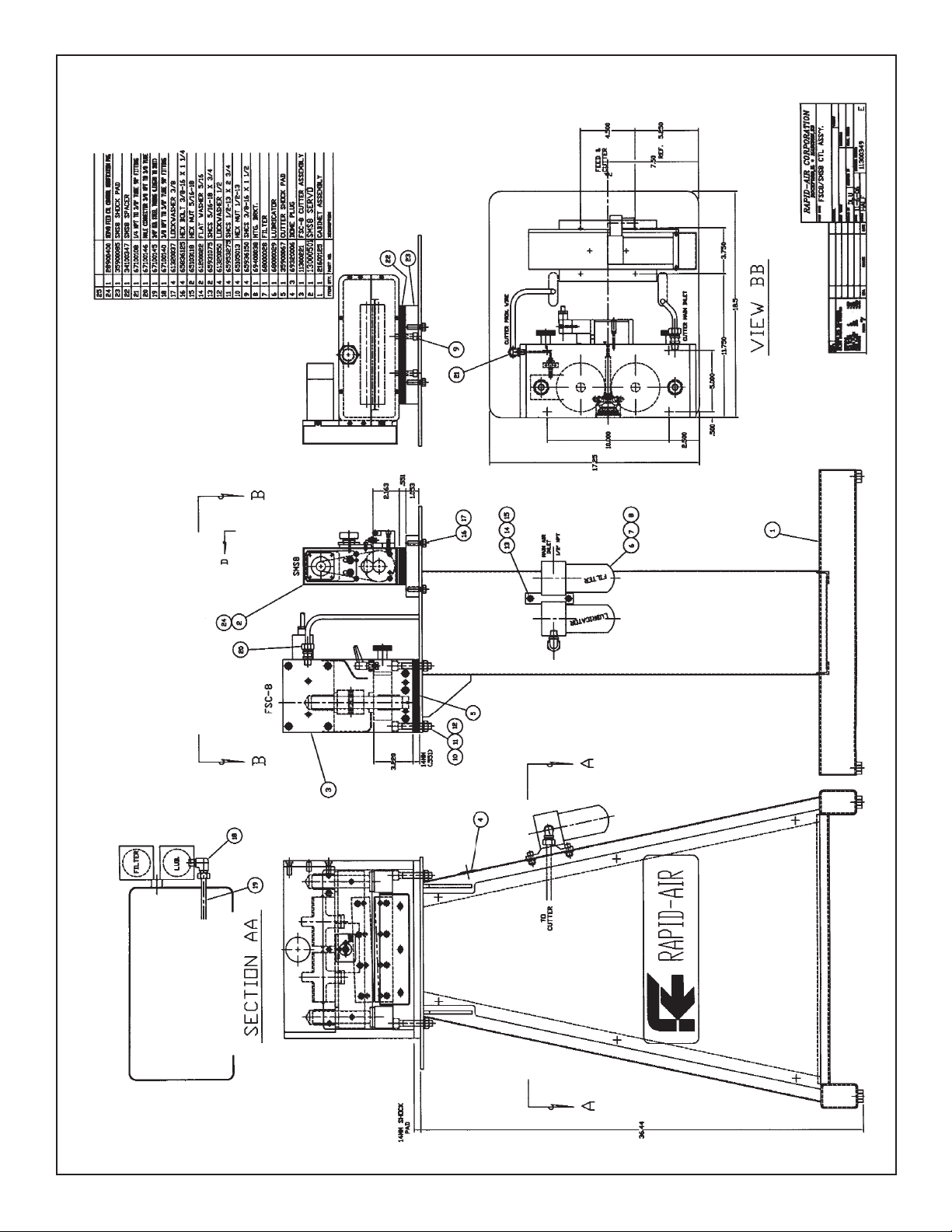
FSC8/SMS8 Control Assembly
9
Page 10

RSC14/SMS2 Servo Control Assembly
10
Page 11

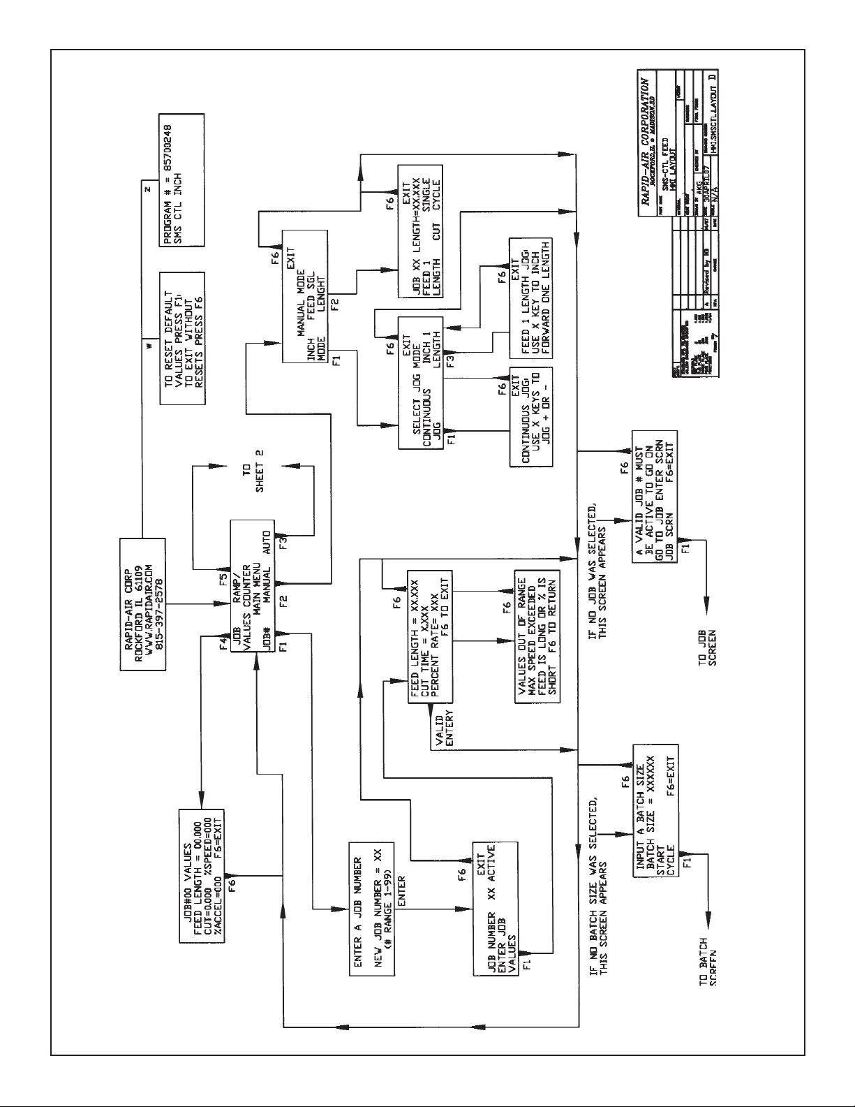
Programming Procedure
Operator Interface Terminal
This section is to familiarize an operator with the terminal screen (program)
flow. Also, the section will explain
how to move from screen to screen.
The screen flow is divided into five
parts as set up in the home screen
– “MAIN MENU”. These divisions are:
1. F1 - JOB ENTRY
2. F2 - MANUAL MODE
3. F3 - AUTOMATIC MODE
4. F4 - REVIEW JOB VALUES
5. F5 - RAMP/COUNTER
The final section is the TROUBLESHOOTING and ERROR CODES.
OVERVIEW
The first screen displayed will look like:
RAPID-AIR CORPORATION
ROCKFORD, IL 61109
WWW.RAPIDAIR.COM
815-397-2578
While the above screen is displayed,
the system is starting up and doing
a self-diagnostic test. If the selfdiagnostic test passes, the program
will start automatically. After a short
delay the main screen will appear.
The “MAIN SCREEN” will look like:
JOB RAMP/
VALUES COUNTER
MAIN MENU
JOB # MANUAL AUTO
SCREEN HINTS
Movement from screen to screen uses
the “F” keys. The “F” key functional
descriptions usually appear above
(F1 to F3) or below (F4 to F6) the keys.
Occasionally, the text will describe the
action caused by an “F” key.
To enter a value, locate the curser (an
underscore line) that will be found below the first character of the number
the program is requesting. As each
character is typed, the cursor will
move to the next digit. The Enter key
may be depressed at any time to enter
current value into memory. When a
value is entered, the program will
check value to ensure that it is a valid
value. A valid entry is a value, which
is in the correct range. A value’s
range is shown by parentheses. If an
invalid number is entered, the cursor
will return to the first character of
the invalid value entered. The cursor will move to the beginning of the
next value needed after a valid entry.
Entering the last value on a screen
will cause the display to move to the
next screen.
SECTION 1 F1 - JOB NUMBER Entry
A job number must be active to do
a manual single feed; an automatic
move, review job values, or edit ramps
or counters. The values entered for
each job will be stored in memory and
available each time that job is selected.
To select an existing job or create a
new job, press F1 while on the “MAIN
SCREEN”. Pressing F1 will display the
“ENTER A JOB SCREEN”. It is:
ENTER A JOB NUMBER
NEW JOB NUMBER = 00
(JOB # RANGE 1-99)
A two-digit number must be entered. An
invalid number will cause the curser to
return to the first digit. After entering a
valid job number, depressing the enter
key will display the following screen:
EXIT
JOB NUMBER 00 ACTIVE
ENTER JOB
VALUES
Selecting F1 will allow values for all
the necessary data for a job to be
entered. The feed advisor will make
the calculations for the job. F6 will
exit to the “MAIN MENU” without
entering or changing any values for
that job. When the F1 is pressed
after selecting enter job values,
the following screen will appear:
FEED LENGTH = 00.000
CUT TIME = 0.000
PERCENT RATE = 000
The feed length is first value required.
A valid feed length distance is 0.001
inches to 99.999 inches. The cut time
is the time the knife blade solenoid is
energized. A valid cut time is between
0.001 and 2.000 seconds. The final
item on this screen is the percent
rate. A valid percent rate is between
1 and 100. After entering valid
values for all three items, the
Feed Advisor will calculate the
motor speed, acceleration and
deceleration. If the speed, accel and
decel are within acceptable limits,
the main screen will reappear. If the
values are outside acceptable limits,
the following screen will appear.
VALUES OUT OF RANGE
MAX SPEED EXCEEDED
FEED IS LONG OR % IS
SHORT F6 TO RETURN
Pushing F4 will take an operator back
to the feed advisor screen. After entering valid data, the “MAIN MENU”
will be displayed.
NOTE: If a job number is not selected
and the selected task requires a job
with a feed length and speed to be
active, the following screen will appear. After a valid job is entered the
program will return to the original task.
11
Page 12

Programming Procedure (continued)
A VALID JOB # MUST
BE ACTIVE TO GO ON
GO TO JOB ENTER SCRN
JOB SCRN F6=EXIT
SECTION 2 F2 - MANUAL MODE
Pressing F2, manual mode while on
the “MAIN MENU”, will cause the
following the screen.
EXIT
MANUAL MODE
INCH FEED SGL
MODE LENGTH
F1, inch mode, produces the following:
EXIT
SELECT JOG MODE
CONTINUOUS INCH 1
JOG LENGTH
F3, feed sgl length, produces the fol-
lowing:
EXIT
JOB 00 LENGTH = 00.000
FEED 1 SINGLE
LENGTH CUT CYCLE
F6, exit, in both screens moves the
display up one level to “MANUAL
MODE”. F1, Continuous jog, allows
an operator to jog each axis in either
direction. The X-axis keys move the
feed axis.
F3, inch 1 length, allows an operator
to inch the material forward one feed
length. The “X” axis keys will move
the axis while a key is pressed until
one feed length is reached. If the key
is released before one feed length is
reached, the axis will stop and wait
until the jog key is pressed again or
one feed length is reached.
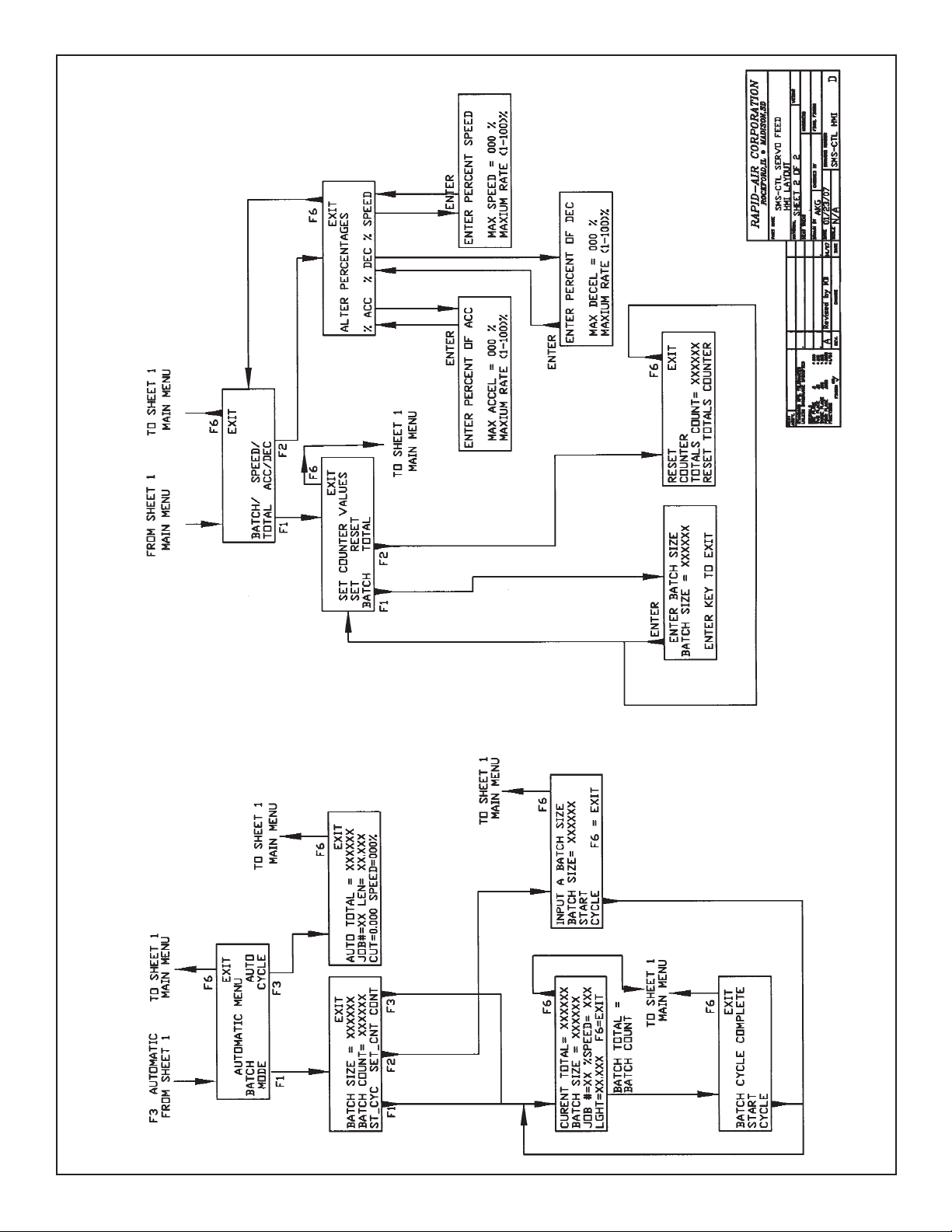
SECTION 3 F3 - AUTOMATIC MODE
Pressing F3, automatic mode while
on the “MAIN MENU”, will cause the
following the screen.
EXIT
AUTOMATIC MENU:
BATCH AUTO
MODE MODE
F1, batch mode, controls batches from
the “BATCH START” screen.
INPUT A BATCH SIZE
BATCH SIZE = 000000
START
CYCLE F6 = EXIT
The F3 key, CONT (continue), will restart a batch stopped before reaching
the full batch size by exiting with the
F6 key. The “BATCH MENU” screen is:
BATCH TOTAL = 000000
BATCH SIZE = 000000
JOB#=00 SPM = 000
BLANK = 00.000 F6 = EXIT
NOTE: If the batch size is set to
000000, the “BATCH SET” screen will
appear. The “BATCH SET” screen will
allow an operator to set the batch
count. The “BATCH SET” screen can
also be found under ramp/count selection on the “MAIN MENU” screen.
The “BATCH SET” screen is shown
above under F2. After the batch size
is entered and F1 (start cycle) is
pressed, the program will return to
“BATCH SET” screen.
When the batch total equals the
batch size, the feed will stop and will
display this screen.
F6, exit, in both screens moves the
display back to “MANUAL MODE”.
F1, inch mode, give the operator two
additional choices. These are:
F1, Continuous jog
EXIT
CONTINUOUS JOG:
USE X KEYS TO
JOG + OR -
F3, inch 1 length
EXIT
FEED 1 LENGTH JOG:
USE X KEY TO INCH
FORWARD ONE LENGTH
EXIT
BATCH SIZE = 000000
BATCH COUNT = 000000
ST_CYC SET_CNT CONT
The F1 key, ST_CYC (start cycle), will
begin the feed/cut cycle. The “BATCH
MENU” screen appears as follows.
CURRENT TOTAL = 000000
BATCH SIZE = 000000
JOB # =00 % SPEED = 000
LGHT = 00.000 F6 = EXIT
The F2 key, SET_CNT (set count), will
allow the operator to set the batch
size or change the batch size. The
“BATCH SET” screen is:
12
EXIT
BATCH CYCLE COMPLETE
BATCH COUNT = 000000
NEW CYCLE
F6, exit, will return to the “MAIN
MENU” screen. F1, start new cycle,
will reset the batch count total to 000000
and will start feeding another batch.
Depressing F3, auto mode, while on the
“AUTOMATIC MODE” screen will display:
EXIT
AUTO TOTAL = 000000
JOB # =00 LENGT = 00.000
CUT = 000 SPEED = 000 %
The automatic cycle will continue
until the F6 key, exit, is pressed.
Page 13

Programming Procedure (continued)
SECTION 4 F4
F4, job values, on the “MAIN MENU”
screen displays the following screen
until F6, exit, is pushed. This screen
lists the current active job number,
the feed length, the SPM, the percentage of speed, the percentage of
acceleration, and if a pilot is used.
JOB # 00 VALUES =
FEED LENGTH = 00.000
CUT = 000 % SPEED = 000
ACCEL = 000 F6 = EXIT
SECTION 5 F5 - RAMP/COUNTER
F5, ramp/counter, on the “MAIN
MENU” screen displays the following
screen:
EXIT
BATCH/ SPEED/
TOTAL ACC/DEC
- JOB VALUES REVIEW
EXIT
SET COUNTER VALUES
SET RESET
BATCH/ TOTAL
F1, set batch, on the “SET COUNTER
VALUES” screen leads to “BATCH
SET” screen discussed above in
SECTION 3.
F2, reset totals, on the “SET COUNTER VALUES” screen resets the total
counter to 000000.
F6, exit, will return to the “RAMP/
COUNTER” screen.
F2, speed/acc/dec, on the “RAMP/
COUNTER” screen leads to:
EXIT
ALTER PERCENTAGES
%ACC %DEC %SPEED
F6, exit, will return to the “RAMP/
COUNTER” screen.
ENTER PERCENT OF ACC
MAX ACCEL = 000 %
MAXIMUM RATE (1 - 100) %
ENTER KEY TO EXIT
The enter key returns the display to
the “ALTER PERCENTAGES” screen.
F2, % dec, allows the deceleration
percentage to be altered with:
ENTER PERCENT OF DEC
MAX DECEL = 000 %
MAXIMUM RATE (1 - 100) %
ENTER KEY TO EXIT
The enter key returns the display to
the “ALTER PERCENTAGES” screen.
F3, % speed, allows the speed
percentage to be altered with:
ENTER PERCENT OF SPEED
MAX SPEED = 000 %
MAXIMUM RATE (1-100) %
ENTER KEY TO EXIT
F1, batch/total, on the
“RAMP/COUNTER” screen leads to:
F1, % acc, allows the acceleration
percentage to be altered with:
The enter key returns the display to
the “ALTER PERCENTAGES” screen.
13
Page 14

troubleshooting
A normally running drive will display an 8 in the LED box, top center. The LED box will display error and fault codes. The keypad
can display additional error codes and information about system operational problems.
LED Box Error Codes
Display Description
0.
1.
2.
3.
4.
5.
6.
7 (not flashing)
7.
8
9
A
b.
c
E.
F.
I
Internal communications error
DC Bus overvoltage level – possibly too high of deceleration
Internal overcurrent, short circuit, over temperature or under voltage fault
Drive overcurrent – check motor cable
DC Bus voltage is below the minimum value – too high an acceleration rate
Feedback trip – check feedback cable
2
Motor or drive I
2
Motor I
Drive over temperature – check internal drive fan
Drive enabled (normal operating mode)
Drive is in torque mode – Not used in Rapid-Air Smart Mini
Drive in Analog Mode – Not used in Rapid-Air Smart Mini
Power base not ready (only on 3 phase drives) – loss of a phase
Cam profile active – Not used in Rapid-Air Smart Mini
General error – error number is on keypad display (see run-time errors below)
Position or velocity following error – possible motor or resolver failure
Drive in electronic gearing mode.
T foldback – motor overloaded or stalled for too long a time
T overload – motor overloaded or stalled
H
h or h.
I
J
J.
o
º.
P. (.flashing)
P. (.steady)
•
r
S
-
-.
=
S
•
1
Drive in a hold state – DIP switch change or PLC request
Homing – Not used in Rapid-Air Smart Mini
Incremental move
Jog move
Preset jog active
Offset move
Overspeed
Positional move
Preset trapezoidal move active – Not used in Rapid-Air Smart Mini
DB (regen resistor) overload
Stop command active
Drive disabled
Crash
Suspend command active
Drive under speed control
Initialization error at power up
14
Page 15

troubleshooting (continued)
Can Status LEDs
There are two CAN LEDs , the left
LED shows activity on the CAN1
(CANopen) bus. The right LED shows
activity on the CAN2 (Baldor CAN)
bus. Each LED can appear green
or red. The states have the following
meanings:
=
NOT LIT: No power to the card.
= GREEN: The bus is operational;
it is experiencing little or no errors.
RUN TIME MML ERROR CODES
Errors 0 to 500 are caused by specialized keywords, and are known as Mint Motion Library (MML) errors.
Errors 3100 and up are general keywords. The most common are also below.
Number Name Description
1 Synchronous MML error Generic error generated when no more specific info is available.
3 Data out of range Data values out of acceptable range for a variable.
9 Out of heap memory Controller is out of memory space.
10 Action not possible Tried to write to a motion keyword while the axis is in motion.
14 Unable to initialize CAN A node returned an error message, other than synchronous or remote.
21 CAN node failed to reply Communication over the CAN bus has timed-out.
22 CAN node not live This error will be generated if you try accessing a node that has died.
27 Problem writing to EEPROM Communication with a remote node timed-out.
28 CAN node - Baud rate The CAN node does not support the requested baud rate.
29 CAN node reported error An error has occurred and cannot be determined further.
34 CAN transmit buffer full This error number should not be reported.
37 Non-volatile data corrupted An error accessing EEPROM or NVRAM data has occurred.
40 Drive is not enabled You have tried starting a move while the drive is disabled.
41 No connection exists There is no connection between the CAN open nodes.
50 Error programming flash The controller has failed to write data to the flash memory.
90 Action not possible The command is not possible whilst the drive is enabled.
121 Error accessing EEPROM EEPROM access has failed.
135 Axis/drive not commissioned The axis/drive is not commissioned.
137 Feedback device comms message is corrupt.
138 Feedback device comms are busy.
139 Feedback device has an error.
147 Static data overrun Static variable is filled, but data remains.
= RED, FLASHING: The bus is passive;
it is experiencing some errors.
= RED: The bus is off; it has experi enced a fatal number of errors.
ERROR CODES IN GENERAL
Various error codes can be displayed
on the operator keypad display. Errors
are divided into two categories –
Run-time Errors and Compilation Errors.
Compilation errors have numbers 2100
to 2400. Compilation errors are based
on programming rules are probably
not arise in normal use, therefore,
are not listed below. If an error with
a number between 2100 and 2400
appears, please consult the Rapid-Air
representative. The most common
Run-time errors and possible causes
are listed below.
RUN TIME GENERAL ERROR CODES
Number Name Description
3100 Division by zero This occurs when the denominator of a division is zero.
3102 Out of memory Array too large to fit in the remaining memory, or function does
not terminate before the internal stacks run out of free storage.
15
Page 16

led status symbols
Symbol Description
Drive / comms watchdog. Internal communications failure. Clear the error; if the problem persists then
contact Baldor technical support.
Over volts. The DC Bus voltage has exceeded the overvoltage level. Check the AC supply voltage is correct
for the unit. Check the DC Bus level. This should be close to the nominal voltage. If the input voltage is correct, then this error may be the result of high deceleration rates. If it is not possible to reduce the deceleration rate, then an external regen resistor should be used. To help you determine the cause of this fault, use
the WorkBench v5 Scope tool to monitor the DC Bus level during moves.
Intelligent Power Module (IPM) trip. The IPM has detected an internal overcurrent, short circuit, over temperature or under voltage fault. Clear the error. If the problem persists, contact Baldor Technical Support or
Rapid-Air.
Overcurrent trip. Current has exceeded 300% of Drive Rated Current. Check the motor cable and
connections for short circuits.
Under volts. The DC Bus voltage has fallen below the minimum undervolts level. This error will only be generated if the drive is in the enabled state. Check the AC supply voltage is correct for the unit. The error could
also occur during high acceleration profiles; to prevent this, reduce the acceleration rate.
Feedback trip. This error indicates loss of encoder/resolver feedback and may indicate that the feedback
cable has become detached, one of the signals has broken, or noise is present. Check the wiring in the
Feedback cable; check the cable screens; check the feedback device fitted to the motor (if possible).
Motor or Drive I
their limit and disabled the drive.
2
T overload. The motor I2T or the drive l.T current protection algorithms have exceeded
(Symbol not flashing)
Motor I
to a level where the drive/motor can recover. The motor / drive can run with demand currents greater than
their rated value for a period of time; after that time the drive will either trip or automatically foldback the
demand current.
Overtemperature. The temperature of the drive has exceeded the trip level or the Motor overtemperature
trip input has been activated. Check that the drives internal fans are functioning. Increase ventilation to the
drive or reduce the ambient temperature.
Drive enabled. The drive is enabled.
Torque mode. The drive is in Torque mode.
Hold to Analog. The axis is in Hold To Analog mode.
Auto tune test driving motor. Autotune is active and driving the motor.
2
T / It foldback. Motor I2T or Drive I.T algorithm has resulted in the demand current being folded back
Warning! The motor shaft may move.
16
Page 17

led status symbols (continued)
Symbol Description
Power base not ready. This error condition applies only to 3-phase models. These drives have a pre-charge
circuit which must activate after power-up before the drive can be enabled. If the drive is enabled before
this then the error occurs. The error could also indicate the loss of one or more of the input phases.
Cam. A cam profile is in progress.
General error. The motion toolbar displays the status of AXISERROR, which is a bit pattern of all latched errors.
Position or velocity following error. A following error has occurred. Following errors could be caused by a
badly tuned drive/motor, especially at high acceleration and deceleration rates where the following error
will typically be greater. The following error limit can be adjusted to suit your application. Following error
could also be the caused by encoder/resolver loss. Confirm that the motor is not overloaded
or stalling. Check the tuning of the drive using the WorkBench v5 Fine-tuning tool. The KVELFF parameter
can be used to reduce following errors during moves.
Follow mode. The drive is in pulse follower or electronic gearing modes.
Hold. The Hold DIP switch is active or the PLC Task has requested a Hold state. Motion will be ramped to
zero demand and will then hold on position while the switch is active.
Homing. The drive is currently homing.
Preset homing active. The drive is currently homing. This motion has been triggered from a Preset move
table.
Incremental move. An incremental move is in progress.
Jog. The drive is Jogging.
Preset jog move active. The drive is Jogging. The Jog was triggered from a Preset jog table.
Offset move. The drive is performing an offset move.
Overspeed. The measured speed of the motor has exceeded the trip level defined by DRIVESPEEDFATAL.
When accelerating to a demand speed close to the trip level, there will typically be a certain amount of
overshoot. Using the Fine-tuning tool, check the amount of overshoot you get with the acceleration and
demand speeds being used in your application.
Positional Move. A point-to-point move is in progress.
(Decimal point flashing)
Preset moves are active, but currently idle (no motion)
17
Page 18

led status symbols (continued)
Symbol Description
Preset trapezoidal move active (in motion).
DB Overload. The regeneration resistor (Dynamic Brake) has been overloaded.
Stop. A STOP command has been issued or the stop input is active.
Drive disabled. The drive must be enabled before operation can continue. A number of actions are required
to enable the drive. See the installation manual supplied with your product.
Crash (various). The drive enable input or the Enable DIP switch have become inactive whilst the drive was
in the enable state (or the drive was enabled whilst they were inactive) - bit 13 in AXISERROR will be set. The
drive can be programmed to ignore this state using DRIVEENABLEINPUTMODE.
Suspend. The SUSPEND command has been issued and is active. Motion will be ramped to zero demand
whilst active.
Speed demand. The drive is under speed control.
Initialization error. An initialization error has occurred at power on.
FlexDrive”, Flex+Drive” And
MintDrive” Options
CAN OPTION / CAN & AUXILIARY I/O OPTION
There are two CAN LEDs on these option cards. On
both options, the left LED shows activity on the CAN1
(CANopen) bus. When the CAN & Auxiliary I/O option is
fitted in a MintDrive”, the right LED shows activity on the
CAN2 (Baldor CAN) bus. Each LED can appear green
or red. The states have the following meanings:
= Not lit: No power to the option card.
= Green: The bus is operational; it is experiencing
little or no errors.
= Red, flashing: The bus is passive;
it is experiencing some errors.
= Red: The bus is off; it has experienced a fatal
number of errors.
DeviceNet Option
There is one Bus Activity LED on this option, which
can appear green or red. The states have the following
meanings:
= Not lit: No power to the option card or there is
no DeviceNet master on the bus.
= Green, flashing: There are one or more devices
on the bus, but there is no communication with
this unit.
= Green: The option is being polled by the
master and is operating correctly.
= Red, flashing: Minor fault, for example an
I/O connection may have timed out.
= Red: Major communications fault, for example,
an incorrect baud rate, a duplicated node ID
(MAC ID), or a bus-off fault.
18
Page 19
SMS - CTL Feed
19
Page 20
SMS - CTL Servo Feed
20
Page 21
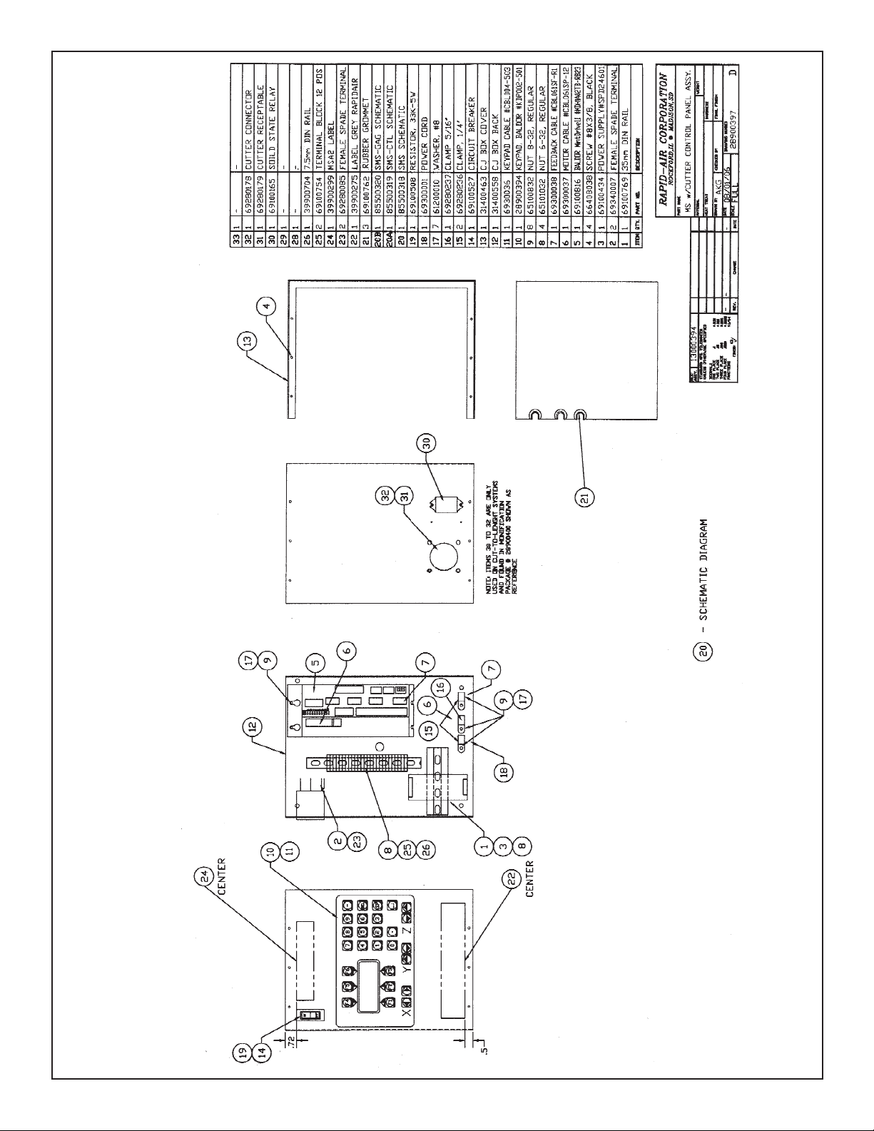
SMS with Cutter Control Panel Assembly
21
Page 22
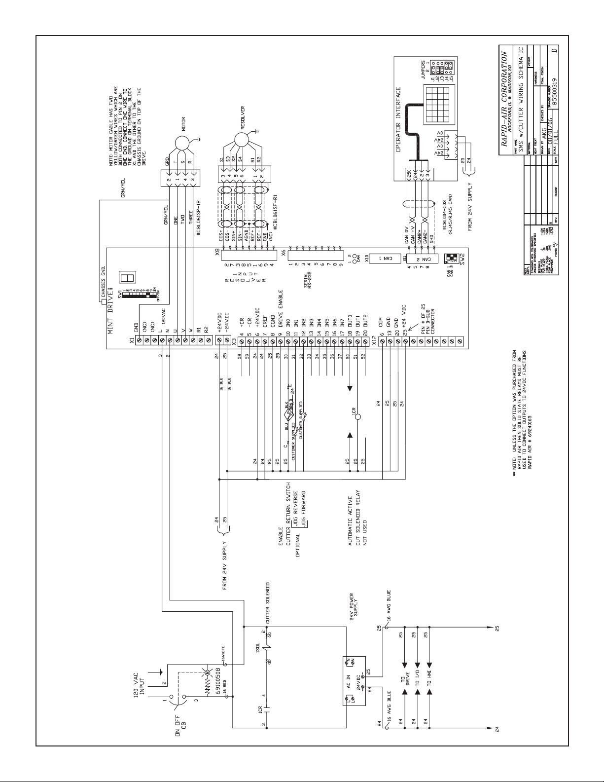
SMS with Cutter Wiring Schematic
22
Page 23

warranty
Warranty Terms & Conditions
ALL SALES BY THE COMPANY ARE MADE SUBJECT TO THE FOLLOWING TERMS AND CONDITIONS. PLEASE READ.
WARRANTY – The Company warrants, for a period of one year from date of shipment by the Company, that the product
shipped is free from defects in material and workmanship. THIS WARRANTY IS EXCLUSIVE AND IN LIEU OF ALL IMPLIED
WARRANTIES IN LAW, INCLUDING MERCHANT - ABILITY. The Company obligation under this warranty is limited to
repairing or replacing, F.O.B. Madison, SD, any part or parts proved to have been defective when shipped. In no event
shall the Company be liable for special or consequential damages. Provisions set forth in specifications are descriptive
and subject to change and are not intended as warranties.
CUSTOMER LICENSE AGREEMENT – The RAPID-AIR CORPORATION reserves the rights in it’s software. The software
program is licensed by RAPID-AIR to the original purchaser of the equipment which contains the software for use only on
the terms set forth in this license.
You may use the program only on the programmable servo computer furnished with the system and only in conjunction
with the servo feed supplied with the system.
You may not without expressed permission from Rapid-Air:
A. Copy, distribute, or document the program for others.
B. Modify or merge any portion of the program for use on non compatible hardware.
C. Make alterations to the program.
23
 Loading...