

Page 1

Straightener and
puShbutton rapid-roll
operating inStructionS
MODELS
SC SERIES
SA3 THROUGH SDX SERIES
(INCLUDES ADJUSTABLE PLATEN STOCK STRAIGHTENER –
SA3 THROUGH SD. 120VAC, 1PH, 60HZ)
(5-07)
RAPID-AIR CORPORATION
4601 KISHWAUKEE ST. • ROCKFORD, IL 61109-2925
Phone: (815) 397-2578
• Fax: (815) 398-3887 • Web Site: www.rapidair.com
1
Page 2

table of contentS
Platen Adjustment Bulletin ...................................................................................................................... pg. 3
Straightener Specification Sheet ............................................................................................................ pg. 4
Pushbutton Control ..................................................................................................................................... pg. 5
Installation ................................................................................................................................................... pg. 5
Start-Up Procedure .................................................................................................................................... pg. 6
Electrical Controls Layout ........................................................................................................................ pg. 6
Dancer Arm Adjustment Explanation ..................................................................................................... pg. 7
Jog and Dancer Arm Setup & Program Adjustments .......................................................................... pg. 8
Standard Straightener Components ........................................................................................................ pg. 9
Operation...................................................................................................................................................... pg. 10
Maintenance ............................................................................................................................................... pg. 10
Troubleshooting Guide .............................................................................................................................. pg. 11
RAMM Board Explanation ........................................................................................................................ pg. 12
Warranty ....................................................................................................................................................... pg. 13
Electrical Schematics ............................................................................................................................... pg. 14-15
Mechanical Parts List P1V-P4V ........................................................................................................... pg. 16-17
Mechanical Parts List SA ...................................................................................................................... pg. 18-20
Mechanical Parts List SB ...................................................................................................................... pg. 21-25
Mechanical Parts List SBX ................................................................................................................... pg. 26-29
Mechanical Parts List SCX ................................................................................................................... pg. 30-36
Mechanical Parts List SD ...................................................................................................................... pg. 37-43
Typing Stamping Layout ............................................................................................................................ pg. 44
2
Page 3
If the straightener is made to correct a clockwise
curvature, it is often impossible to correct a
counterclockwise curvature. The only available
adjustment is the variation of the degree of bend
at each station. This is true even for straighteners
that have banked upper rolls that pivot for
two-point adjustment.
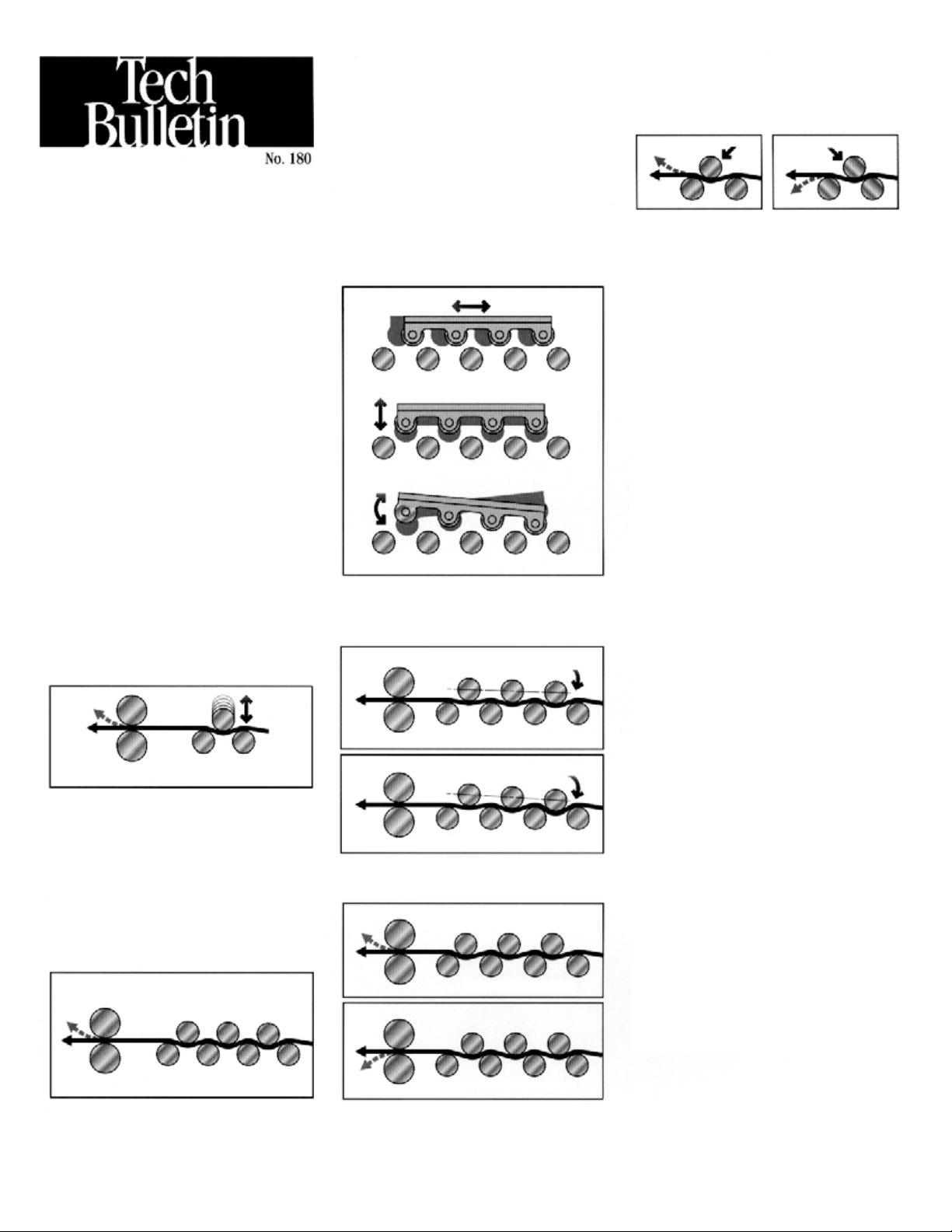
To more easily explain the concept, Figure 8
shows a three-roll combination with the upper
roll forward and Figure 9 shows a three-roll
combination with the upper roll to the rear.
Figure 8 Figure 9
Adjustable Platen
Stock Straighteners
vs.
Straighteners with
Traditional
Vertical Roll
Adjustment
CONCEPT: The concept behind a movable
platen containing the upper bank of rolls for
straighteners can be somewhat difficult to
grasp, but once the principles are understood
the superiority of this system becomes obvious.
To explain the differences between the adjustable platen system and one that uses traditional
single-point vertical roll adjustment, we are
describing both types of systems here.
VERTICALLY ADJUSTABLE UPPER ROLLS:
For centuries the bending of materials has been
done by variations of a three-roll arrangement as
illustrated in Figure 1.
Figure 1
Downward curvature of material
to remove coil set
Bending occurs when one roll is forced into the
space between the other two rolls for downward
curvature of the material to remove coil set.
Pressroom straighteners add multiple three-roll
combinations in order to level the material in
small increments at each stage. This method can
provide acceptable results for some materials,
but is limited because correction of material
curvature is effective in only one direction as
illustrated in Figure 2.
Figure 2
SIX-WAY UPPER ROLL ADJUSTMENT: After
manufacturing straighteners with vertically
adjustable rolls for many years, Rapid-Air
developed and patented the adjustable platen
type straightener as illustrated in Figure 3.
Figure 3
Forward/Back
Up/Down
Up/Down Slant
This design mounts the upper rolls in a platen
which can be adjusted for degree of bend as
illustrated in Figure 4 and Figure 5
Figure 4
Light material distortion
Figure 5
Heavy material distortion
Less deflection
Deeper deflection
and for curvature direction as shown in
Figure 6 and Figure 7.
Figure 6
Rolls forward – curve up
Figure 7
Notice that the sharpest bend occurs where two
rolls are in close proximity. When the upper
roll is forward, the curvature will be up and
when the forward roll is adjusted to the rear,
the bend will be down. The degree of bend can
be adjusted by a combination of vertical and
horizontal adjustments.
ADVANTAGES: The high degree of flexibility
afforded by the adjustable platen design provides
a predictable straightening method for a wide
variety of materials and takes a lot of the “Black
Magic” out of pressroom straightener setup.
The reduction in the flexing and distortion of
the strip of material and the reduction of the
straightening power required allows effectiveness with heavy materials. Additionally, the ability
to place rolls in a proper close proximity allows
effective straightening with very thin materials.
ROLL DIAMETER: The smaller the roll
diameter in a straightener the better it is able to
remove distortions in the strip of material, but
this factor is compromised by the requirement
of larger rolls in wider models of straighteners
in order to prevent deflection of the rolls
themselves. Rapid-Air straighteners are designed
to optimize all factors (including number
of rolls, diameter and position) within the
published material capacities and specifications
for each model.
SWING-OPEN TOP: Rapid-Air developed and
introduced the swing-open top for straighteners
in order to facilitate the cleaning of rolls and the
threading of a new strip of material through the
straightening rolls. For convenience and safety,
each top is counterbalanced and held in the
open position until it is clamped for operation.
Roll adjustment settings are maintained when the
top is closed and locked.
AVAILABILITY: All models of Rapid-Air straighteners are presently available with the adjustable
platen design with an expanded range of models
being introduced in the coming months.
Material curvature is effective
in only one direction
Rolls back – curve down
3
Page 4
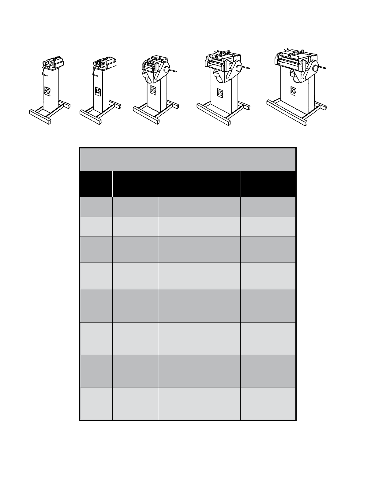
SA
Series
SB
Series
SBX
Series
SCX
Series
rapid-air Straightener Model Selection
SD
Series
Max Effective Max
Material Straightening Speed
Model Width Range per min
SA3 3” (76mm) .002” - .030” (.051-.76mm) 700” (1778cm)
SA3M 3” (76mm) .002” - .030” (.051-.76mm) 1,400” (3556cm)
SB4 4” (102mm) .003” - .050” (.076-1.27mm) 700” (1778cm)
SB4M 4” (102mm) .003” - .050” (.076-1.27mm) 1,400” (3556cm)
SBX4 4” (102mm) .004” - .080” (.10-2.03mm) 825” (2100cm)
SBX8 8” (203mm) .004” - .070” (.10-1.78mm) 825” (2100cm)
SBX12 12” (305mm) .004” - .060” (.10-1.52mm) 825” (2100cm)
SBX4M 4” (102mm) .004” - .080” (.10-2.03mm) 1,650” (4200cm)
SBX8M 8” (203mm) .004” - .070” (.10-1.78mm) 1,650” (4200cm)
SBX12M 12” (305mm) .004” - .060” (.10-1.52mm) 1,650” (4200cm)
SCX6 6” (152mm) .006” - .100” (.15-2.54mm) 825” (2100cm)
SCX12 12” (305mm) .006” - .090” (.15-2.29mm) 825” (2100cm)
SCX18 18” (457mm) .006” - .080” (.15-2.03mm) 825” (2100cm)
SCX24 24” (610mm) .006” - .065” (.15-1.65mm) 825” (2100cm)
SCX6M 6” (152mm) .006” - .100” (.15-2.54mm) 1,650” (4200cm)
SCX12M 12” (305mm) .006” - .090” (.15-2.29mm) 1,650” (4200cm)
SCX18M 18” (457mm) .006” - .080” (.15-2.03mm) 1,650” (4200cm)
SCX24M 24” (610mm) .006” - .065” (.15-1.65mm) 1,650” (4200cm)
SCX6H 6” (152mm) .006” - .080” (.15-2.03mm) 4,100” (10400cm)
SCX12H 12” (305mm) .006” - .070” (.15-1.78mm) 4,100” (10400cm)
SCX18H 18” (457mm) .006” - .060” (.15-1.52mm) 4,100” (10400cm)
SCX24H 24” (610mm) .006” - .055” (.15-1.40mm) 4,100” (10400cm)
SD6 6” (152mm) .006” - .125” (.15-3.18mm) 825” (2100cm)
SD12 12” (305mm) .006” - .125” (.15-3.18mm) 825” (2100cm)
SD18 18” (457mm) .006” - .100” (.15-2.54mm) 825” (2100cm)
SD24 24” (610mm) .006” - .090” (.15-2.29mm) 825” (2100cm)
4
Page 5
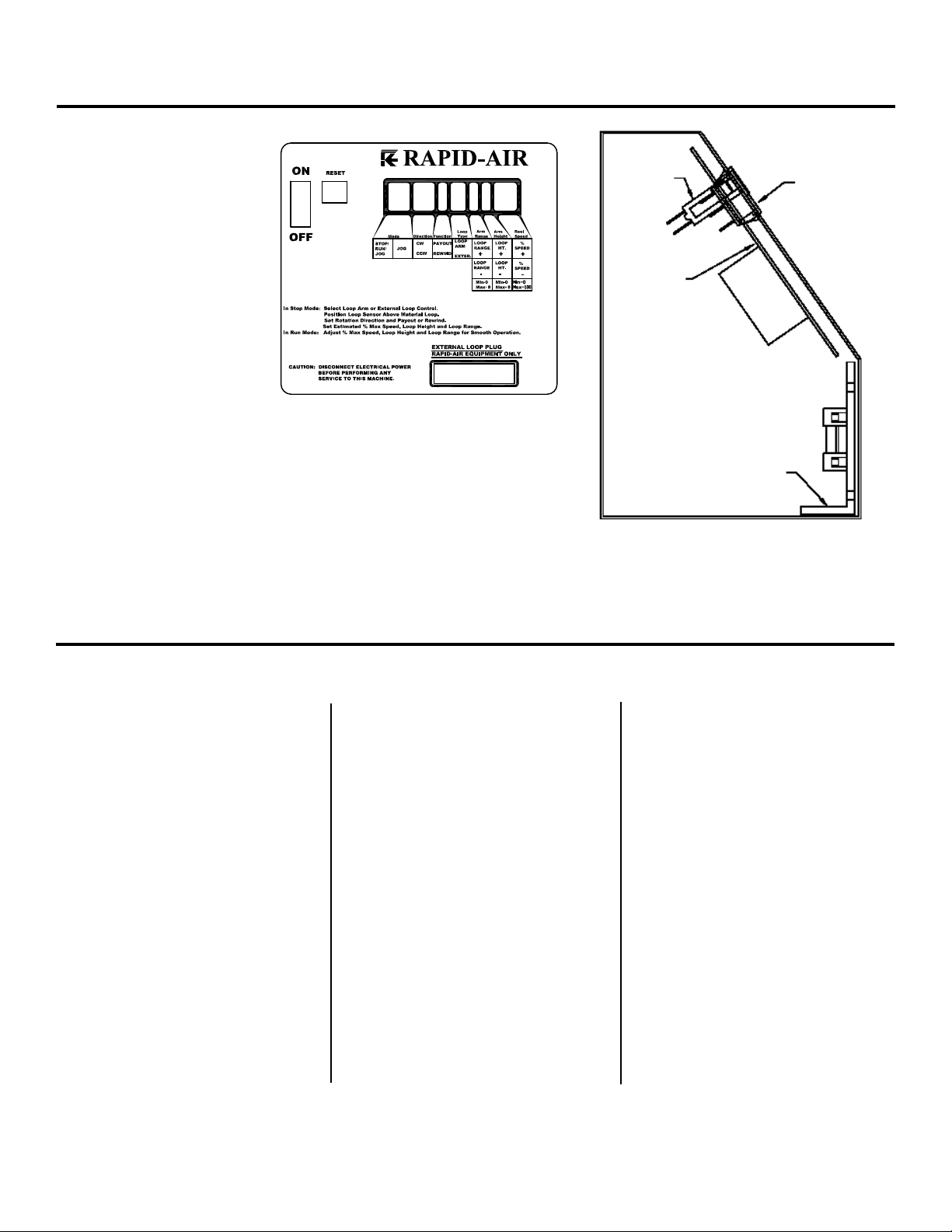
puShbutton control
The main control unit
is located behind the
pushbutton cover.
Here is an illustration of
the layout of the control
panel. This diagram lists
all the components and
the approximate location
of each that could be
used for troubleshooting
the machine if a problem
should occur. The reel
is shipped with—120 VAC
(1 phase) input. Visually
check all electrics before
starting the reel.
MAIN
BREAKER
69100578
CONTROL
BOARD
69100804
ROCKER
SW.
69100315
MOTOR
BOARD
69100014
inStallation
Operating Instructions For SBX Series Powered Straightener
The straightener that you just
received is fully assembled and tested
and ready to be put into position.
CAUTION: Due to shipment vibration,
the straightener should be checked to
be sure that all screws and bolts are
secure and all electrical components
are in place inside the cabinet. Visually inspect the complete machine for
physical damage due to shipment and
handling. If the straightener was damaged in shipment, contact the carrier
first and then Rapid-Air.
Install the straightener on a level
surface with sufficient clearance for
loading the material and adjusting
the roller pressure for straightening.
Align and center the straightener to
the device that it will be supplying the
straightened stock. The straightener
should then be bolted to the floor
especially when used to pull stock
from a non-powered reel.
CAUTION: Before bolting the
straightener down, check for the
longest feed length to be run. The
straightener should be set so that
there will be about two or three feed
lengths in storage in the loop without
re-inducing coil set in the material.
The standard speed straightener
is completely self contained and
only needs to be plugged into a
20 amp, 120 VAC, 60 HZ outlet. If an
extension cord is used as a source
to the straightener power, it should
be a minimum 12 gauge wire to keep
the voltage losses down and also for
electrical safety reasons.
Please check your local safety codes.
The medium and high speed
straighteners require 230 VAC, 60 HZ,
1PH as the supply voltage. Please
refer to the schematics in the manual
for required fuse sizes.
Please check your local safety codes.
Turn on the main power button and
run a test cycle checking the jog
(using the jog button) and run
(using the dancer arm to test that the
speed varies if using the proportional
control). Test all electrical features
before continuing.
5
Page 6

Start up procedure
Prior to applying power to the machine the operator should review all the controls on the machine. A brief summary of the
controls is listed below.
Main Console And Controller
The main pushbutton control box is
mounted on the top of the straightener frame. Located on the face of the
console are eleven pushbuttons, one
display, one on/off switch, one circuit
breaker, one external loop plug and
inside the box is motor board and one
potentiometer when required, all of
which are explained below.
1. % SPEED POT
The % speed function adjusts the
maximum speed that the straightener
will feed and should be set to maintain a constant feed rate. Adjustable
in the run mode.
2. ON/OFF SWITCH
This illuminated switch is the main
power switch for the controller. It must
be “ON” for the machine to function.
3. RUN/STOP/JOG
SELECTOR SWITCH
This function selects between Run,
Stop and Jog. If in Run and the control
arm is moved the rolls will turn. If in
Jog, the Jog button has to be de-
pressed for the rolls to turn. If in Stop,
there should be no movement of the
rolls even if the dancer arm is raised
or lowered or the jog pushbutton is
pressed.
4. JOG BUTTON
Used for intermittent movement of
material on the rolls, mainly used for
set up or getting material thru the
straightener and over to the pulling
device. Active in jog mode only.
5. DANCER ARM LOOP HEIGHT
AND RANGE ADJUSTMENT
a. Loop Range – The loop range func-
tion adjusts the amount the dancer
arm will travel to provide the full
range of speed of the straightener.
There are eight positions available.
b. Loop Height – The loop height function is used for setting the start position of the control arm. The setting determines when the straightener rolls
will start turning. Each position will
move the operating start position up
from the home position to accom-
modate specific material rest height
requirements.
6. LOOP ARM / EXTERNAL SWITCH
This switch selects either dancer arm
(internal) by displaying “LV” for loop
arm vertical reel or “LH” for loop arm
horizontal reel (PMD) or external loop
control by displaying “RT” for the
RTB and ”RS” for the RS_1. The RLL
will work on the “RT” selection.
7. RESET BUTTONS
a. 15 amp – This is the main circuit
breaker for the 120 VAC input
straightener.
8. REMOTE INTERFACE
PORT “D” CONNECTOR
This connector is used to communicate with external loop control equipment.
CAUTION: Never plug any type of computer or non Rapid-Air equipment into
this plug or severe damage will result.
Always consult with the factory when
installing new external controls for
compatibility and wiring information.
Electrical Component Description
69100804 board - main reel control board
69100014 (RAMM) - D.C. motor board
29100021 dancer arm potentiometer
69100578 circuit breaker
69100315 rocker switch
6
Page 7
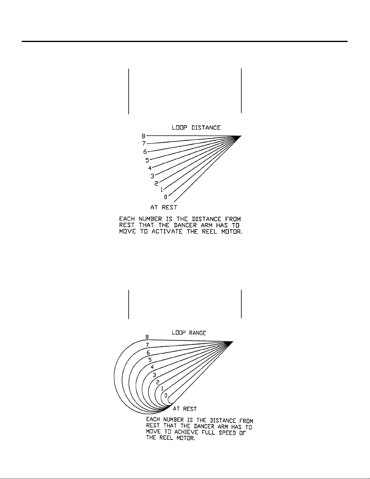
dancer arM loop
Dancer Arm Loop Height Adjustment
Eight different loop sensing arm
operating positions can be selected
during set-up. The material thickness
determines the dancer arm rest
position. Once the material is
threaded up and the dancer arm
is resting on the material and the
reel runs in the rest position then
select a higher number on the height
adjustment until the reel stops
rotating. The zero point of the dancer
arm is raised from its no material rest
position to the current rest position
angle shown (as indicated 0-8). The
dancer arm will start the material
dereeling from the new rest position
selected. The function is active and
can be changed in the run mode.
Dancer Arm Loop Range Function
The loop range function selects the
degree of arm movement to achieve
maximum motor speed selected. If a
loop range of “0” was selected then
the arm would only have to move
approximately 10 degrees to have the
reel at full speed whereas if the loop
range “8” was selected then the arm
would have to move almost the full
travel or approximately 90 degrees to
get to full speed. The function is active
and can be changed in the run mode.
7
Page 8

dancer arM adjuStMent explanation
JOG SPEED AND DANCER SET-UP
The straightener was shipped with
the dancer arm set up for its correct
position so the only thing that has to
be reset would be the jog speed if you
need it to jog faster or slower. The
rest of the keypad is pretty much self
explained so become familiar with the
keypad positions for making adjustments on the fly. Turn on the main
power switch and select “LV” for loop
arm vertical at “Loop Type” on the
pushbuttons.
MAKING INTERNAL
PROGRAM ADJUSTMENTS
Turn off the main power switch,
press and hold the “Run/Stop/Jog”
button while turning the main
power switch on. The first screen
you see will display the jog speed
percentage.
JOG SPEED 23% +
NEXT -
If you want the jog speed faster
then press the “Reel Speed “+ ““ %
speed pushbutton. If you want the jog
speed slower then press the “Reel
Speed “-”” % speed pushbutton. The
jog speed is shown in percent of max
jog speed. If the jog speed is “OK “
then push the “Run/Stop/Jog button”
once for next.
The next screen asks if you want to
set up the sensor. As before the percent speed buttons are used for the
yes-no. Select “no” if all you wanted
to do was set the jog speed. Select
“yes” if you want to reset the dancer
arm position setup. And then “next”.
SETUP SENSOR YES
NEXT NO
The next screen asks you to set the
low set point. If the dancer arm is at
“No Material Rest” then just save
the setting by pushing the Stop/Run
Jog pushbutton.
SENSOR LOW SETPOINT
SAVE XXX
The next screen is for setting the high
set point. Raise the dancer arm to
its upper stop position and press the
save or Stop/Run/Jog button once.
SENSOR HIGH SETPOINT
SAVE XXX
The next screen is to set the offset of
the program. Potentiometers are hard
to get set from left to right so we built
in an offset. If you set the low and
high range and go into run and the
reel runs for no reason then an offset
has to put in. Go through the setup
procedure again and put in an offset
of –3 to –5 and now the pot is zero.
LOW OFFSET + 0 +
NEXT -
You have now set the dancer arm
limits. The next screen is to exit the
setup and start working
EXIT SETUP? YES
NO
Choose yes and next and the next
screen appears .
SHUT OFF POWER TO
SAVE AND EXIT
The dancer arm is now ready for
production running.
8
Page 9

Standard Straightener coMponentS
Curve Up/Down Adjustment
Some applications have dies that cannot accept anything but flat stock
and other dies run better with the material curving up or down to miss the
built-in edge required in the die. Before this feature was added, operators
would under straighten or over
straighten the material to suit their
needs but in doing so would severely
change the material entering the die.
This not only caused feeding problems but part quality problems. With
this feature, curve up or down can be
accomplished by changing the position of the rolls without stressing the
material.
optional Straightener coMponentS
Entrance Cascade Roll
The entrance cascade roll assembly
is used to maintain a support arc for
stock entering a feed. The cascade
roll has three extra rollers to help the
material flow better.
Exit Cascade Roll
The straightener is shipped with
the exit side pre-drilled for the
cascade roll or guide roll block.
The entrance and exit use the
same components.
Entrance Guide Roll Block
All straighteners are shipped with
an entrance guide roll block. This
contains a roller and two adjustable
edge guides.
Angle Bracket
Rapid-Air offers this accessory that
mounts between the straightener
head and the base. It angles the
exit side of the straightener twelve
degrees lower than the entrance
side. This feature works very well
when using the straightener to pull
off a non-powered reel.
9
Page 10

operation
Once the straightener has been
tested and all the functions work
then it should be tested for what it
was designed to do and that is to
remove coil set.
Retract all of the idler rolls and the
exit pinch roll to a position so when
the cover is closed the material is
not being deformed. Open the cover
of the straightener and position the
edge guides for maximum width. Cut
and place about a four foot length of
the material onto the straightener
rolls with the exit end of the material extending through the exit pinch
rolls and centered from side to side
in the straightener. Close the cover
and latch it. Adjust the exit pinch roll
enough to grip and hold the material.
Adjust the edge guides so that they
just touch the material.
Adjust the first idler roll knob, this is
the one nearest the entrance of the
straightener, so that it deforms the
material no more than the thickness
of the material. Adjust the second
idler roll knob so it is lightly on the roll.
Run the material to check that the exit
pinch roll is not slipping on the material, readjust if necessary. This piece
will still have coil set in the first two
feet of the material as it was not run
through the complete straightening
cycle. At this time, this piece could be
rerun and checked for straightness or
a new piece could be cut and run and
then be checked.
A good check is to guide the exiting
material, keeping it parallel to the
rolls, until the run is complete and then
hold one end of the material in the air
while peering down the length of the
material. If the material still has “coil
set” then readjust roll pressure on the
last roll, towards the exit end but before
the pinch roll, until the material is
straight. Run one or more short length
setups while making final adjustments.
Once the proper setting has been determined, the quick release top maintains the adjustment during loading.
Thread the material from the reel
through the straightener, under the
dancer arm, and into the pulling
device leaving ample loop between
the straightener and the pulling
device. If the material thickness
is such that when exiting the
straightener, it will not let the
dancer arm down to the rest
position, then either lengthen the
dancer arm or adjust the loop height
until the straightener stops feeding.
Set the % speed potentiometer to
50% for a starting position and
start the pulling device to have
the material feeding. If the straightener gets finished and stops before
material is needed again then the
straightener is set to feed too
fast, slow it down by adjusting the
% speed potentiometer. The ideal
straightening is to have the
straightener slightly exceed the
feed rate required. This minimizes
the starting and stopping and
resultant stock deformation.
Maintenance
Lubrication
Gear transmission:
The reservoir oil capacity is about 3
to 12 oz. depending on the size of the
straightener. The reservoir oil should be
changed every 2000 hours and should
be filled to the oil level site gauge.
Use MOBILE 600W cylinder oil or
equivalent. This is a non synthetic oil.
Rolls:
Although the rolls should be cleaned
periodically they never have to be
10
greased as all the rolls have permanently lubricated bearings.
Drive Belt:
At the oil change interval, check for
belt tension and wear.
Page 11

troubleShooting guide
MAIN SWITCH ON BUT NOT LIT
1. CB tripped.
a. Reset CB
2. Unit not plugged into
main power.
a. Plug into main power source.
3. No power in incoming line.
a. Check outlet.
b. Check power cord.
4. Loose wiring.
a. Check terminals and
connections.
MOTOR CREEPS IN
STOP POSITION
1. “Min” speed pot on RAMM board
out of adjustment.
2. Dancer arm could be bent which
changes the home position of
the arm.
UNIT TURNS BUT WON’T JOG
1. Jog function was not selected.
a. Select jog.
2. Jog speed has not been set up.
a. Call factory.
UNIT ON BUT MOTOR WON’T RUN.
(ARMATURE VOLTAGE PRESENT –
ON RAMM BOARD)
1. Check motor wiring.
a. Replace motor cord or correct
motor wiring. Call factory.
2. Check motor.
a. Worn brushes or motor
defective. Call factory.
b. Check for oil in motor, gear box
seal could have ruptured.
UNIT ON BUT MOTOR WON’T RUN.
(NO ARMATURE VOLTAGE ON
RAMM BOARD)
1. Selector switch not in run
position.
a. Turn selector switch to
run position.
2. If running with a dancer arm
control.
a. Check that the external/loop
arm function is in the loop arm
position.
3. If running with external control.
a. Check that the external/loop
arm function is in the
external position.
4. Loop height switch setting
too high.
a. Set height setting to “0”.
5. Percent speed function set
too low.
a. Adjust percent speed
function to 100%.
6. Fuses blown.
a. Check fuses & circuit breaker.
7. No AC voltage at DC drive board.
a. Check wiring.
8. Check signal voltage between
P2 to P1 on DC drive.
0-6 VDC—RAMM
0-9 VDC—Regen Drive
while moving dancer arm.
a. If there is a signal, check
continuity between I1 & I2.
b. If no continuity, replace D.C.
drive or call factory.
9. Check Pico fuse on 69100804
board (F1).
a. Replace fuse, 1 amp pico
fuse—call factory.
11
Page 12
Safety warning – pleaSe read carefully
RAMM Solid State DC Motor Speed Control
This product should be installed and
serviced by a qualified technician,
electrician or electrical maintenance
personnel familiar with its operations
and the hazards involved. Proper installation (see instruction information
which accompanies product), which
includes wiring, mounting in proper
enclosure, fusing or other over current protection and grounding, can reduce the chance of electrical shocks,
fires or explosion in this product or
products used with this product, such
as electric motors, switches, coils
solenoids and/or relays. Eye protection must be worn when working with
control under power. This product is
constructed of materials (plastics,
metals, carbon, silicon, etc.) which
may be a potential hazard. Individual
material safety data sheets (MSDS)
are available upon request. Proper
shielding, grounding and filtering of
this product can reduce the emission
of radio frequency interference (RFI)
which may adversely affect sensitive
electronic equipment. If information
is required on this product, contact
our factory. It is responsibility of the
ultimate user of this product to read
and comply with this safety warning.
(SW effective 1/89).
***IMPORTANT***
YOU MUST READ THESE
INSTRUCTIONS BEFORE
OPERATING CONTROL
1. Be sure AC line voltage
corresponds to control voltage.
TABLE 1: NOMINAL TRIMPOT SETTINGS
MIN (minimum speed): 15% CL (current limit/torque): 65%
MAX (maximum speed): 65% ACCEL (acceleration start): 20%
IR (IR compensation): 25% DECEL (deceleration stop): 20%
For motor drive board instructions, go to www.info@kbelectrics.com and find
KBMM write up which is closest to the Rapid-Air RAMM board.
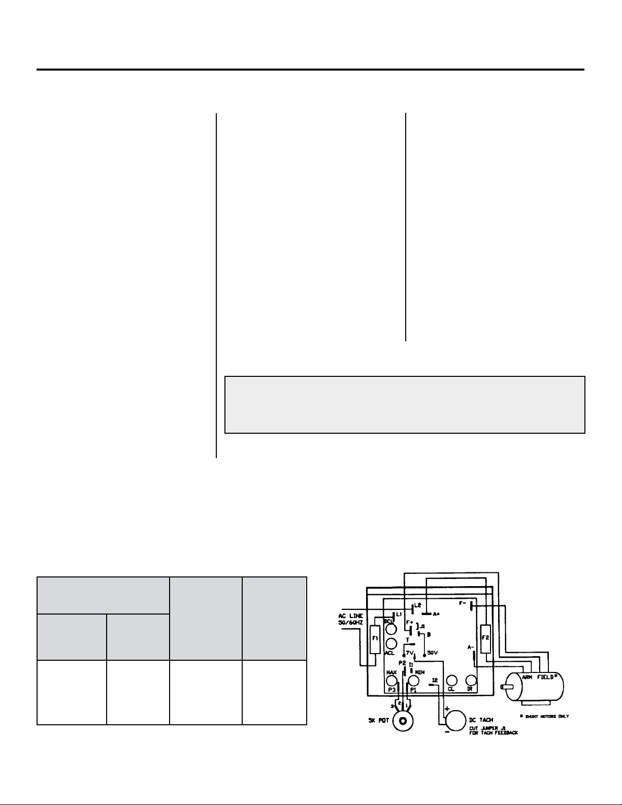
2. Install the correct Plug-In
Horsepower Resistor according
to armature voltage and motor
horsepower.
3. Recheck connections: AC line to
L1 and L2; armature to A+ and
A– and field (Shunt motors only
to F+ and F-.) (
in improper direction, interchange
armature leads.)
4. Install proper AC line fuse and
armature fuse as required.
5. Nominal trimpot settings are as
follows (expressed in % of full
CW rotation):
Note: If motor runs
Plug In Horsepower Resistor
A Plug-In Horsepower Resistor must be installed to match the RAMM to the motor
horsepower and voltage. See table 2 for the correct value. Plug-In Horsepower
Resistors are stocked by your distributor.
TABLE 2: PLUG IN HORSEPOWER RESISTOR CHART
MOTOR HORSEPOWER
RANGE **
Armature
Voltage
90-130 VDC
1/4
1/2
3/4
1**
* Motor horsepower and armature voltage must be specified when ordering so that proper
resistor will be supplied.
** For overlapping motor horsepower range use lower value Plug-In Horsepower Resistor.
*** Auxiliary heat sink must be used to achieve HP rating.
Armature
Voltage
180 VDC
1/2
1
1-1/2
2***
Plug-in
Horsepower
Resistor
Resistance
Value (ohms)
.05
.025
.015
.01
Rapid-Air
P/N
69100529
69100530
69100534
69100531
12
Page 13

warranty
Limited Warranty – RAMM 125, 225, 225D
For a period of one (1) year from date of original purchase Rapid-Air Corporation will repair or replace without charge
devices which our examination proves to be defective in material or workmanship. This warranty is valid if the unit has not
been tampered with by unauthorized persons, misused, abused or improperly installed and has been used in accordance
with the instructions and/or ratings supplied. The foregoing is in lieu of any other warranty or guarantee expressed or
implied, and we are not responsible for any expense (including installation and removal), inconvenience, or consequential
damage, including injury to any person, caused by items of our manufacture and/or sale. Some states do not allow certain
exclusions or limitations found in this warranty so that they may not apply to you. In any event, Rapid-Air Corporation’s total
liability, under all circumstances, shall not exceed the full purchase price of this unit.
13
Page 14
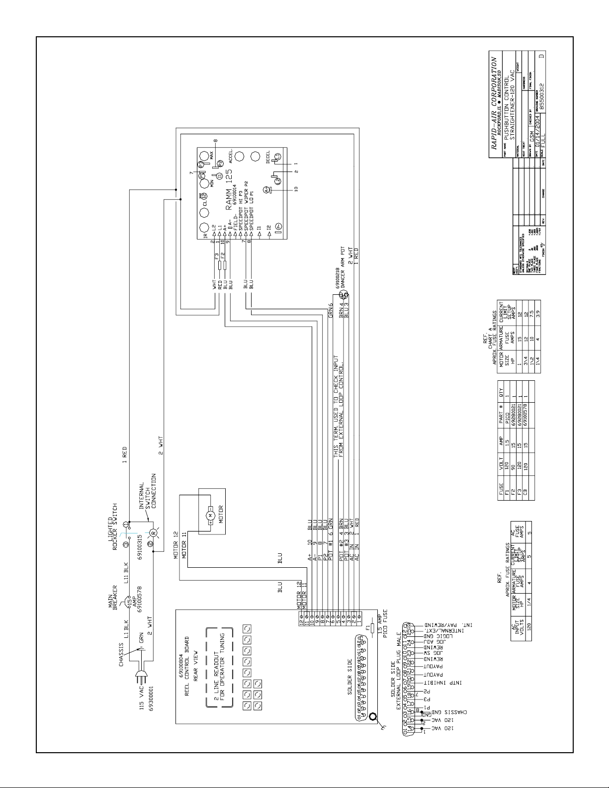
Pushbutton Control Straightener - 120 VAC
14
Page 15

Pushbutton Control Straighteners - 2 and 3HP
15
Page 16

Gear Head Assembly - P1V
16
Page 17

Gear Head Assembly - P1V
17
Page 18

SHT.
1/3
26 4 00 0 2 7
ROCKFORD, IL • MADISON, S.D.
RAPID-AIR CORPORATION
PART NAME
PART NO. DESCRIPTION
1 40 32900289 PIN, PIVOT 2
1 39 32900288 PIN, PIVOT 2
1 38 32900287 PIN, PIVOT 2
2 37 32900286 PIN, PIVOT 2
1 36 36100024 FITTING, WORM COVER 3
1 35 32600012 WORM 3
3 34 32600034 GEAR 3
1 33 32600035 GEAR, IDLER 3
1 32 32600071 GEAR, WORM 3
11 31 32600086 GEAR, SPUR 2
1 30 32600087 GEAR, SPUR 3
1 29 32600088 GEAR, SPUR 3
1 28 32600089 GEAR, PINION 2
1 27 32600090 RACK 2
7 26 34200061 ROLLER 2
5 25 34200060 ROLLER, DRIVE LOWER 2
2 24 34200059 ROLLER 3
1 23 32900229 SHAFT, WORM 3
1 22 32900228 SHAFT, WORM GEAR 3
1 21 32900226 SHAFT, IDLER 3
7 20 32900284 SHAFT, ROLLER 2
1 19 32900283 SHAFT, GUIDE 2
1 18 32900280 SHAFT, IDLER 3
6 17 32900279 SHAFT, IDLER 2
1 16 32900282 SHAFT, ROLLER UPPER 3
1 15 32900281 SHAFT, ROLLER LOWER 3
1 14 34100119 SPACER, SQUEEZE 2
1 13 34100121 SPACER, UPPER 3
1 12 34100120 SPACER, LOWER 2
1 11 31900428 GUIDE 2
1 10 31900429 BRACKET, GUIDE SUPPORT 2
1 9 31900408 BRACKET, SQUEEZE 2
1 8 31900407 BRACKET, SQUEEZE 3
1 7 31900406 BRACKET, IDLER 2
1 6 31500124 COVER, GEAR CASE 3
1 5 31500123 COVER, ROLLER SUPPORT 2
1 4 30100054 FRAME, DRIVE SIDE 3
2
ANCHOR, SPRING BOTTOM
2 80 37500044 SPRING, COMP. 2
2 79 37500043 SPRING, TEN. 2
2 78 37500042 SPRING, COMP. 2
2 77 37500041 SPRING, COMP. 2
2 76 37500040 SPRING, COMP. 2
2 75 64510002 BEARING, THRUST 3
2 74 64520008 BEARING, THRUST 3
1 73 64520010 BEARING, THRUST 2
1 72 64500031 BEARING, NEEDLE 3
28 71 64500033 BEARING, NEEDLE 2
5 70 64500036 BEARING, NEEDLE 2
69
6 68 64500034 BEARING, NEEDLE 2
11 67 64500030 BEARING, NEEDLE 2
1 66 64500029 BEARING, NEEDLE 3
5 65 64500028 BEARING, NEEDLE 2
4 64 64500003 BEARING, NEEDLE 3
3 63 64500002 BEARING, NEEDLE 3
2 62 64500032 BEARING, NEEDLE 3
3 61 36700017 KNOB 2
2 60 34200005 ROLLER 2
2 59 36200005 NUT 2
1 58 65230004 NUT, LOCK 2
2 57 36200018 NUT, LOCK 2
1 56 66700041 THUMB, SCREW 2
1 55 36700015 KNOB 2
1 54 31500127 GUARD, LOWER 3
1 53 31500126 GUARD, UPPER 3
52 3
1 51 31500125 COVER 2
1 50 31900415
1 49 31900414 ANCHOR, SPRING TOP 2
1 48 31900413 BAR, CLAMP 2
1 47 31900412 PIVOT, BLOCK 2
1 46 31900411 ADJ. TEE HORIZ. 2
2 45 31900409 LINK 2
F
H
1 44 31900410 LINK, UPPER 2
QTY. ITEM
1 3 30100053 FRAME, CONTROL SIDE 3
1 2 31500111 COVER. WORM 3
1 1 30100057 HOUSING, GEAR 3
SHT.
I ECN 4703 10-01
H ECN 3500 1-94
G ECN 3212 7-92
STANDARD MFG. TOLERANCES
DECIMALS:
ONE PLACE .0 ± .030
PART NO. DESCRIPTION
QTY. ITEM
1 43 22900285 ECCENTRIC TRUNION 3
1 42 32900227 PIN, PIVOT 3
1 41 32900290 PIN, HINGE 2
SHT.
SA3 STRAIGHTENER HEAD ASSY
F ECN 2549 4-90
TWO PLACE .00 ± .010
E ECN 1302 4-87
THIRD PLACE .000 ± .005
C.R.A.
3-27-85
D ECO 1028 7-85
SCALE
HEAT TREAT HARDNESS
DRAWN BY CHECKED BY FINAL FINISH
DATE DRAWING NUMBER SHT
C ECO 0970 5-85
B ECO 0962 5-85
A ECO 0905 4-85
SYMBOL CHANGE DATE
3 ± 1/64
THE ABOVE TOLERANCES APPLY UNLESS
OTHERWISE SPECIFIED
CHAMPERS ± .005
FINISH 63
FRACTIONS
MATERIAL
FOUR PLACE .0000 ± .0005
1 119 63130375 PLUG, PIPE 3
2 118 63130125 PLUG, PIPE 2
1 117 37600058 GASKET 3
1 116 37600059 GASKET 2
1 115 33700016 STUD, ADJ. 2
1 114 33700015 STUD, ADJ 2
1 113 33700014 STUD, ADJ. 2
1 112 65600004 INSERT, THREADED 2
3 111 65600002 INSERT, THREADED 2
5 110 60200049 SEAL, SHAFT 2
1 109 36800010 KEY 3
4 108 36800005 KEY 3
2 107 61810213 KEY, WOODRUFF 3
1 106 62412125 ROLLPIN 2
3 105 62412062 ROLLPIN 2
1 104 62409050 ROLLPIN 3
2 103 62325150 PIN, DOWEL 3
10 102 62305075 PIN, DOWEL 3
2 101 62325100 PIN, DOWEL 2
5 120 65936475 SCREW, SHCS 3/8-16x4-3/4 2
G
SA3 Straightener Head Assembly
1 156 62319025 DOWEL PIN 3
7 155 63800125 BALL 2
1 154 34700034 WASHER 3
1 153 69420011 BREATHER 2
1 152 69420010 BREATHER 3
1 151 39900091 LABEL 3
1 150 39900092 INSTRUCTION PLATE 3
149
1 148 37901000 COUPLING, OLDHAM 3
14 147 35800051 RETAINER, SEAL 2
2 146 34100003 SPACER 3
14 145 34700048 WASHER 3
1 144 64520010 WASHER 2
1 143 34700061 WASHER 2
1 100 62312062 PIN, DOWEL 2
1 142 34700060 WASHER 2
3 141 34700062 WASHER 2
1 140 64520005 WASHER 3
6 99 62312025 PIN, DOWEL 2
11 139 64520002 WASHER 3
H
18
PART NO. DESCRIPTION
2 98 33600168 PIN, INDICATOR 2
3 97 60910037 RING, RETAINING 2
13 96 60910025 RING, RETAINING 2
14 95 60910015 RING, RETAINING 2
1 94 60910031 RING, RETAINING 2
6 93 60910062 RING, RETAINING 3
1 92 60810062 RING, SPIRAL 3
1 91 60108916 “O” RING 3
1 90 60108146 “O” RING 3
1 89 60108024 “O” RING 3
1 88 31800024 PLATE, SEAL 3
14 87 37600062 SEAL, SHAFT 2
1 86 60200005 SEAL, SHAFT 3
3 85 60200043 SEAL, SHAFT 3
1 84 37500046 SPRING, FLAT 2
3
QTY. ITEM
1 83 37500026 SPRING, WAVE 3
1 82 37500012 SPRING, COMP. 2
2 81 37500045 SPRING, COMP. 2
SHT.
SCREW, PHIL. PAN 10-32x3/8
PART NO. DESCRIPTION
2 134 35900007 SCREW, STOCK GUIDE 2
1 133 36100044 SCREW, ADJ. HORIZ. 2
132
21 138 34700057 WASHER 2
6 137 61300037 WASHER 3
2 136 61300010 WASHER 2
2 135 65936175 SCREW, SHCS 3/8-16x1-3/4 3
4 131 65820062 SCREW, HHCS 1/4-20x5/8 3
4 128 65920075 SCREW, SHCS 1/4-20x3/4 3
8 126 65936125 SCREW, SHCS 3/8-16x1-1/4 3
4 130 66612037 SCREW, BHCS 10-32x3/8 3
4 129 66700701
5 125 66212025 SCREW, SHSS 10-32x1/4 2
8 127 65920125 SCREW, SHCS 1/4-20x1-1/4 3
12 124 65912037 SCREW, SHCS 10-32x3/8 2
QTY. ITEM
1 123 65912087 SCREW, SHCS 10-32x7/8 3
1 122 65912200 SCREW, SHCS 10-32x2 3
1 121 66536100 SCREW. FHCS 3/8-16x1 2
Page 19

SA3 Straightener Head Assembly
19
Page 20

SA3 Straightener Head Assembly
20
Page 21

SB4 Straightener Head Assembly
21
Page 22

SB4 Straightener Head Assembly
22
Page 23

BILL OF MATERIAL PAGE 1
SB4 STNR HEAD ASSY 0-700 1PM ASM #26400029
ITM PART # QTY DESCRIPTION
1
2
3
4
5
6
7
8
9
10
11
12
13
14
15
16
17
18
19
20
21
22
23
24
25
26
27
28
29
30
31
32
33
34
35
36
37
38
39
40
41
42
43
44
45
46
47
48
49
50
51
52
53
54
33700011 B
36700017 B
37500040 A
31900417 C
31500129 D
32900301 B
60910031 B
37500012
62309025
32900297 B
69420011 N
63800093
32900298 B
62325062
64500040 C
63130250
60500001
34700064 B
64500041 C
34200062 B
62237200 N
31900415 B
31900414 B
31900423 B
32900303 B
31900422 B
31900421 B
60910037 B
64520010 B
31900420 B
67410008
36700018 B
33700017 B
64500018 B
64520006 B
60910062 B
31500130 B
65912050 B
37500051
32600109 B
36800005 N
32600034 B
62319050
34700094 B
34300053 N
32900299 B
65230004 N
36200018 B
62337100
66212025 N
39900092 B
62412125
60108111
39900093 B
1 STUD, ADJ.
3 KNOB
2 SPRING, COMP’N LEE LC-045E-6
1 IDLER ROLL BRKT SB4
1 COVER SB4
5 IDLER SHAFT SB4 STNR
12 RET RING 5100-31
1 SPRING, SPEC STOCK CLAMP F56-A
6 DOWEL PIN Q21-093025
6 LOWER DRIVE ROLLER SB4 STNR
1 BREATHER VENT *FLUID PWR ASP-1-BV
5 BALL Q32-093
5 IDLER SHAFT SB4 STNR
2 DOWEL PIN Q21-250062
11 BEARING NEEDLE TORR M-781 CL END
1 PIPE PLUG Q23-25
2 STAT-O-SEAL WASH, PARKER 600-3/8
10 WASHER, SB4 STNR.
10 BEARING NEEDLE TORR JTT-59 DBL SL
5 IDLER ROLL SB4 STNR
2 PULL DOWEL JERGENS 31707 3/8 X 2
1 ANCHOR, SPRING BOTTOM
1 ANCHOR, SPRING TOP
1 LINK, UPPER SB4 STNR
2 HINGE PIN SB4 STNR
2 LINK, SB4 STNR
1 HORIZ. ADJ. BLOCK, SB4 STNR
1 RET RING 5100-37
3 RACE, THRUST TORR. #TRA-613
1 PIVOT BLOCK, SB4 STNR
1 WAVE WASHER ASC. SPG. W0484-009
1 ADJUSTABLE KNOB, SB4 STNR
1 HORIZ. ADJ. SCREW, SB4 STNR
1 BEARING TORR B1010
2 BEARING TORR TRB-1018
8 RET RING 5100-62
1 COVER, SPRING SB4 STNR
4 SCREW, CAP, SOC. HD. Q8-02050
1 SPRING COMP LEE #LC120L-4
1 RACK SB4 STNR
5 KEY 3/16 x 3/16 x 1/2
4 GEAR-DRIVE
1 DOWEL PIN -- 11 WASHER, THRUST
2 STOCK GUIDE COLLAR STAFFORD 10L
1 GUIDE ROLL SHAFT SB4 STNR
1 NUT, LOCK 3/8-16 JERGENS 28101
2 NUT, LOCK, KNURLED 5/16-24 x 1/4
2 DOWEL PIN Q21-375100
3 SCREW, SOC SET, CUP PT Q10-02025
1 INSTR. PLATE - CURVE ADJ.
1 ROLL PIN Q18-125125
2 O RING Q1-8111
1 LABEL, ROLLER IND SB4 STNR
23
Page 24

BILL OF MATERIAL PAGE 2
SB4 STNR HEAD ASSY 0-700 1PM ASM #26400029
ITM PART # QTY DESCRIPTION
55
56
57
58
59
60
61
62
63
64
65
66
67
68
69
70
71
72
73
74
75
76
77
78
79
80
81
82
83
84
85
86
87
88
89
90
91
92
93
94
95
96
97
98
99
100
101
102
103
104
105
106
107
108
64500042 C
61200026 B
31500111 B
30100040 R
30100056 D
30100055 D
37500026 N
32900294 B
32900228 B
64500031 C
65912200
64510002 B
64520005 B
36100024
60108916
60810062 B
36800010 A
32600012 B
60200005 B
32900229 B
37901000 B
10000005
65936175
65936100
66220025 N
65920075 B
63130375
63130125
69420010 B
31500120 B
31500119 B
65912075 B
66612037
65936550 N
65936125
34100003
61300037 N
65820062
34100027 B
34100124 B
34100125 C
64500032 C
61810002
60910050 B
31500128 D
32600110 B
65920150 N
32900296 B
60910043 B
34700063 B
60200047
64500001 C
37600060 B
32601200
1 BEARING, NEEDLE TORR. B-76
1 WASHER Q5-26
1 WORM GEAR COVER P1V CSTG#50110009
1 GEAR HOUSING P1V CSTG #50110121
1 CONTROL SIDE FRAME SB4
1 DRIVE SIDE FRAME SB4
1 SPRING-WASHER ASSOC. SPR W1102-01
1 UPPER ROLLER SHAFT SB4 STNR
1 WORM GEAR SHAFT P1V
1 BEARING, NEEDLE TORR B-128
1 SOCKET HD CAPSCREW Q8-02200
2 BEARING, NEEDLE THRUST Q53-2
1 BEARING TORR TRD-1220
1 WORM COVER 113-P1V
1 O RING Q1-8916
1 RET RING SPIROLOX RS 62
1 KEY
1 WORM, P1V STD.
1 OIL SEAL CR 6204
1 SHAFT WORM P1V
1 COUPLING, OLDHAM R3, R4, S4V, S8V
1 FILLER - NO PART REQUIRED
2 SOCKET HD CAPSCREW Q8-066175
2 SOCKET HD CAPSCREW Q8-066100
3 SCREW, SOC HD SET, 1/4-20 X 1/4
4 SCREW, CAP, SOC. HD. Q8-040075
1 PIPE PLUG Q23-37
2 PIPE PLUG Q23-12
1 BREATHER VENT F.P. ENG ASP-3-BV
1 EXIT GUARD LOWER P4V
1 EXIT GUARD UPPER P4V
4 SCREW, CAP, SOC. HD. Q8-02075
8 BHMS 10/32 x 3/8
5 SOC HD CAPSCREW 3/8-16 x 5-1/2
5 SOCKET HD CAPSCREW Q8-066125
2 SPACER 44B-P1V
6 SPLIT LOCK WASHER 3/8 MEDIUM DUTY
4 HEX HD. CAP SCREW Q15-040062
1 SPACER, SQUEEZE ROLL BRACKET P4V
1 UPPER SPACER SB4 STNR
1 LOWER SPACER SB4 STNR
2 BEARING, NEEDLE TORR. JTT-1010
1 #2 WOODRUFF KEY 3/32 X 1/2
1 RET RING 5100-50
1 GEAR COVER SB4
1 SPUR GEAR 38T, 16P, SB4 STNR
5 SOCK HD CAP SCREW 1/4-20 x 1-1/2
1 IDLER SHAFT SB4 STNR
13 RET RING 5100-43
21 WASHER, SB4 STNR.
11 OIL SEAL TROSTEL 01 EB 040 028 02
12 N. BRG. B-78 7/16 x 5/8 x 1/2 LG
1 GASKET, SB4 STNR
12 GEAR –MTE–
24
Page 25

BILL OF MATERIAL PAGE 3
SB4 STNR HEAD ASSY 0-700 1PM ASM #26400029
ITM PART # QTY DESCRIPTION
109
110
111
112
113
114
115
116
117
118
119
120
121
122
123
124
125
126
127
128
129
130
131
132
133
134
135
136
137
138
139
140
141
142
143
144
145
146
147
148
149
150
62309100 B
32900302 B
60200043 B
31800024 B
60108024
66700041 N
61810213
37500023 B
34200040 B
65912100
64520002 B
60108146
32900295 B
66536100 N
64500002 B
64500003 B
62325150
37600058 C
62409050
32600071 B
32900226 A
32600035 B
32900227 A
31900408 B
31900418 B
62325075
32900056 B
37500041 A
37500045 A
37500050 N
62412062
32900300 B
64500025 C
65600007
32600111 B
31900419
61200022
33700015 B
66300250 B
39900051 B
39900261 B
34700034 B
1 PIN, DOWEL 3/32 x 1 INCH LG.
1 IDLER BRKT HINGE PIN SB4 STNR
3 SEAL SHAFT EB-52-40-2 TROSTEL
1 SEAL PLATE P1V
1 O RING Q1-8024
1 SCREW, THUMB 3/8-16 JERGENS 43910
2 KEY Q30-213
1 SPRING, FLAT SQUEEZE 36B-P4V
2 ROLLER, PINCH P4V
1 SOCKET HD CAPSCREW Q8-02100
9 BEARING TORR TRC 1018
1 O RING Q1-8146
1 LOWER ROLLER SHAFT SB4 STNR
1 SCREW, CAP, SOC FLAT HD 3/8-16 x 1
1 BEARING TORR B108
5 BEARING TORR B1012
2 DOWEL PIN Q21-250150
1 GASKET
1 ROLL PIN Q18-093050
1 WORM GEAR P1V
1 IDLER SHAFT P1V
1 GEAR-IDLER
1 PIVOT PIN P1V
1 BRACKET, SQUEEZE ROLLER
1 SQUEEZE ROLL BRACKET SB4 STNR
10 DOWEL PIN Q21-250075
1 TRUNNION, ECCENTRIC S4V
2 SPRING, COMP’N LEE LC-040C-2
2 SPRING, COMP LEE # LC-45E-10
2 SPRING, TENSION LEE #LE-037D-1
3 ROLL PIN Q18-125062
1 HINGE PIN, COVER SB4 STNR
2 BEARING NEEDLE TORR BH-1012
2 INSERT, THD. JERGNES 26123
1 SPUR GEAR 16T, 16P, SB4 STNR
1 CLAMP BAR SB4 STNR
3 WASHER Q5-22
2 STUD, ADJ. 5/16-24 x 1.62
2 SCREW, DRIVE Q17-025
1 NAMEPLATE, .875 x 1.500
1 CAUTION, LABEL
1 THRUST WASHER
* RECORD NUMBER
PSRV
25
Page 26

SBX-4 Straightener (Standard Speed) with Pushbutton Controls
26
Page 27

SBX-4 Straightener (Standard Speed) with Pushbutton Controls
27
Page 28

SBX-4 Straightener (Standard Speed) with Pushbutton Controls
28
Page 29

SBX-4 Straightener (Standard Speed) with Pushbutton Controls
29
Page 30

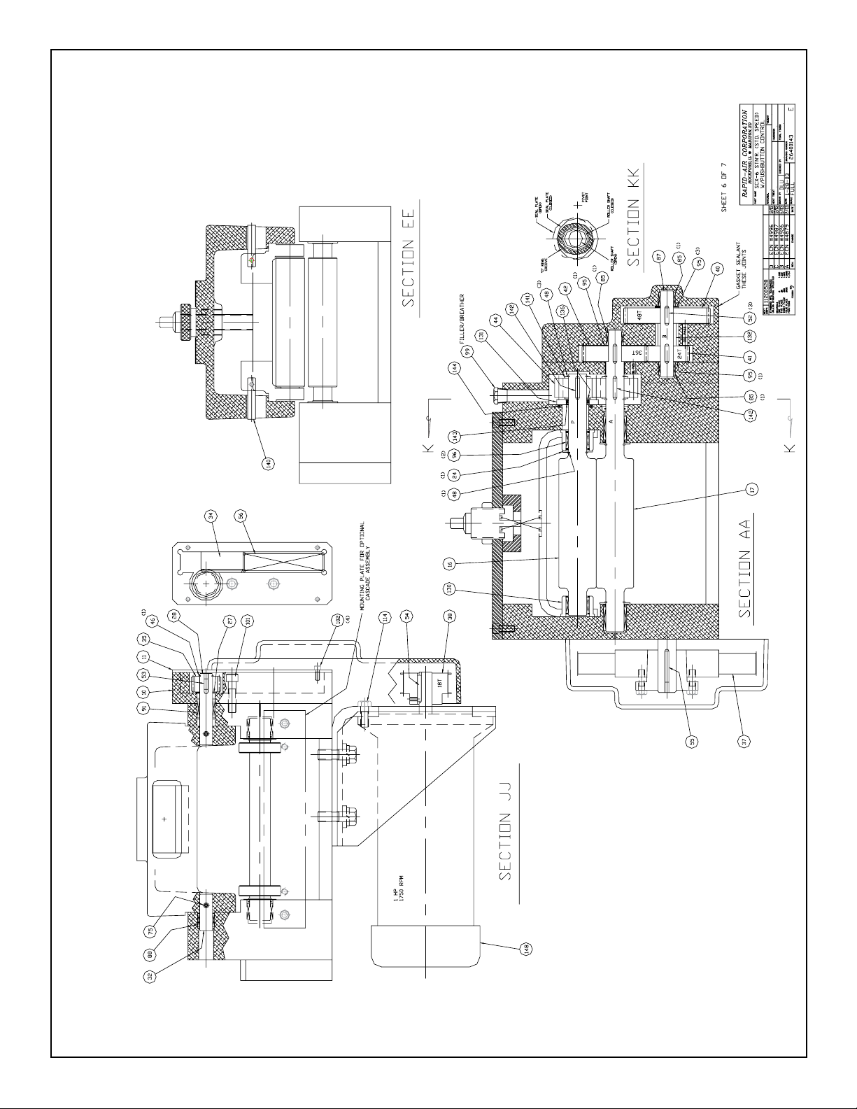
SCX-6 Straightener (Standard Speed) with Pushbutton Controls
30
Page 31

SCX-6 Straightener (Standard Speed) with Pushbutton Controls
31
Page 32

SCX-6 Straightener (Standard Speed) with Pushbutton Controls
32
Page 33

SCX-6 Straightener (Standard Speed) with Pushbutton Controls
33
Page 34

SCX-6 Straightener (Standard Speed) with Pushbutton Controls
34
Page 35
SCX-6 Straightener (Standard Speed) with Pushbutton Controls
35
Page 36

SCX-6 Straightener (Standard Speed) with Pushbutton Controls
36
Page 37

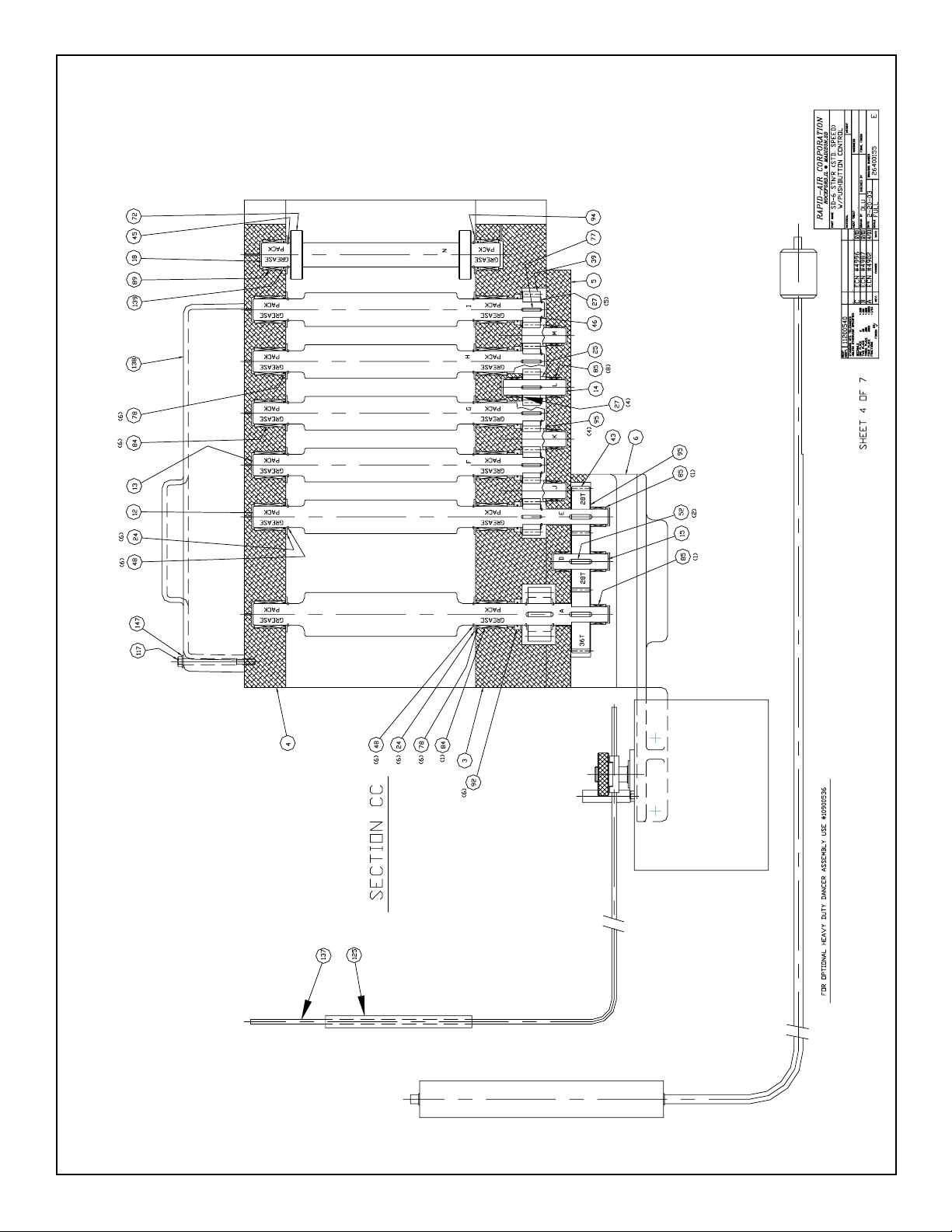
SD-6 Straightener (Standard Speed) with Pushbutton Controls
37
Page 38

SD-6 Straightener (Standard Speed) with Pushbutton Controls
38
Page 39

SD-6 Straightener (Standard Speed) with Pushbutton Controls
39
Page 40
SD-6 Straightener (Standard Speed) with Pushbutton Controls
40
Page 41

SD-6 Straightener (Standard Speed) with Pushbutton Controls
41
Page 42

SD-6 Straightener (Standard Speed) with Pushbutton Controls
42
Page 43

SD-6 Straightener (Standard Speed) with Pushbutton Controls
43
Page 44

Typical Stamping Layout
44
 Loading...