

Page 1

Straightener / rapid-roll
operating inStructionS
MODELS
SA3 - SD WITH COMPACT CONTROL
(5-07)
RAPID-AIR CORPORATION
4601 KISHWAUKEE ST. • ROCKFORD, IL 61109-2925
Phone: (815) 397-2578
• Fax: (815) 398-3887 • Web Site: www.rapidair.com
1
Page 2

table of contentS
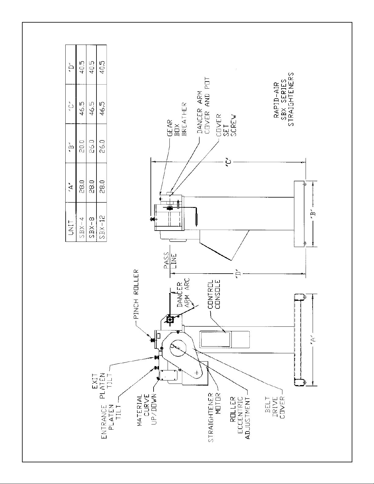
Straightener Layout Sheet SBX ............................................................................................................... pg. 3
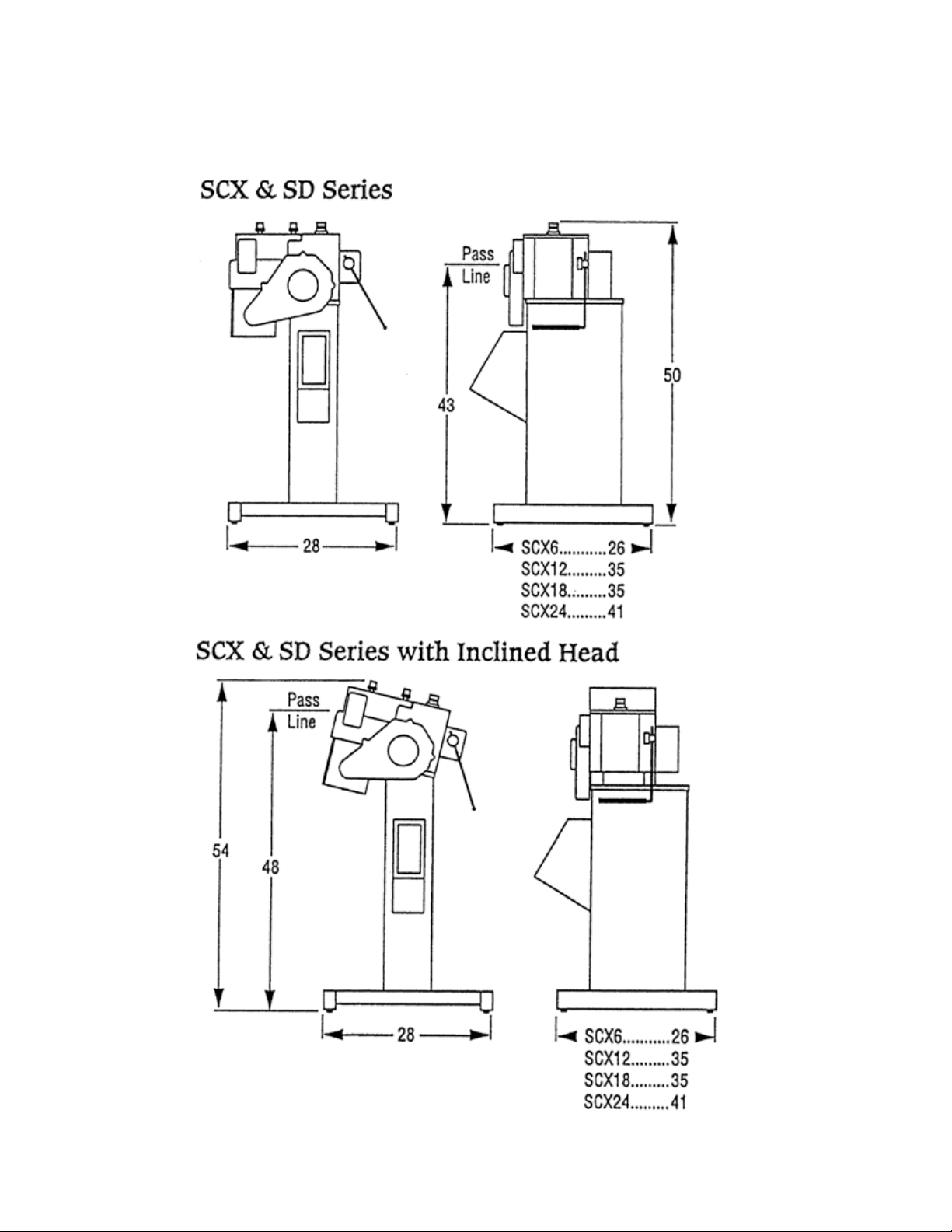
Straightener Layout Sheet SCX ................................................................................................................ pg. 4
Platen Adjustment Bulletin ...................................................................................................................... pg. 5
Specifications ............................................................................................................................................. pg. 6
Installation ................................................................................................................................................... pg. 7
Start-Up Procedure .................................................................................................................................... pg. 8
Electrical Controls Layout ........................................................................................................................ pg. 9-10
Dancer Arm Adjustment Explanation ..................................................................................................... pg. 11
Standard and Optional Components ....................................................................................................... pg. 12
Operations.................................................................................................................................................... pg. 13
Maintenance ............................................................................................................................................... pg. 13
Troubleshooting Guide .............................................................................................................................. pg. 14
Taut Stock Explanation .............................................................................................................................. pg. 15
RAMM Board Explanation ........................................................................................................................ pg. 16-19
Warranty ....................................................................................................................................................... pg. 20
Electrical Schematics ............................................................................................................................... pg. 21-23
Mechanical Parts List SBX ................................................................................................................... pg. 24-27
Mechanical Parts List SCX .................................................................................................................... pg. 28-33
Typical Stamping Layout ........................................................................................................................... pg. 34
Straightener SA3 - SB4 ............................................................................................................................. pg. 35-36
Rapid Roll .................................................................................................................................................... pg. 37-38
2
Page 3
3 4 5
Page 4
Page 5
If the straightener is made to correct a clockwise
curvature, it is often impossible to correct a
counterclockwise curvature. The only available
adjustment is the variation of the degree of bend
at each station. This is true even for straighteners
that have banked upper rolls that pivot for
two-point adjustment.
To more easily explain the concept, Figure 8
shows a three-roll combination with the upper
roll forward and Figure 9 shows a three-roll
combination with the upper roll to the rear.
Figure 8 Figure 9
Adjustable Platen
Stock Straighteners
vs.
Straighteners with
Traditional
Vertical Roll
Adjustment
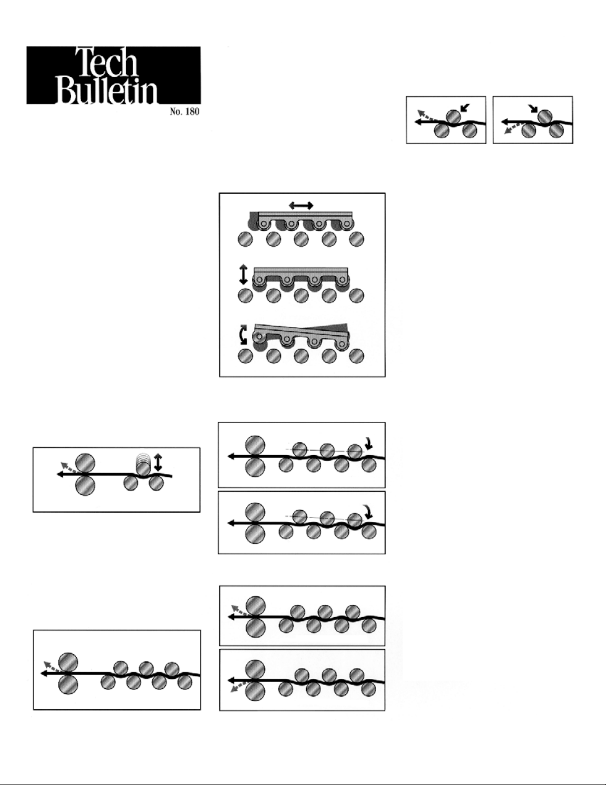
CONCEPT: The concept behind a movable
platen containing the upper bank of rolls for
straighteners can be somewhat difficult to
grasp, but once the principles are understood
the superiority of this system becomes obvious.
To explain the differences between the adjustable platen system and one that uses traditional
single-point vertical roll adjustment, we are
describing both types of systems here.
VERTICALLY ADJUSTABLE UPPER ROLLS:
For centuries the bending of materials has been
done by variations of a three-roll arrangement as
illustrated in Figure 1.
Figure 1
Downward curvature of material
to remove coil set
Bending occurs when one roll is forced into the
space between the other two rolls for downward
curvature of the material to remove coil set.
Pressroom straighteners add multiple three-roll
combinations in order to level the material in
small increments at each stage. This method can
provide acceptable results for some materials,
but is limited because correction of material
curvature is effective in only one direction as
illustrated in Figure 2.
Figure 2
SIX-WAY UPPER ROLL ADJUSTMENT: After
manufacturing straighteners with vertically
adjustable rolls for many years, Rapid-Air
developed and patented the adjustable platen
type straightener as illustrated in Figure 3.
Figure 3
Forward/Back
Up/Down
Up/Down Slant
This design mounts the upper rolls in a platen
which can be adjusted for degree of bend as
illustrated in Figure 4 and Figure 5
Figure 4
Light material distortion
Figure 5
Heavy material distortion
Less deflection
Deeper deflection
and for curvature direction as shown in
Figure 6 and Figure 7.
Figure 6
Rolls forward – curve up
Figure 7
Notice that the sharpest bend occurs where two
rolls are in close proximity. When the upper
roll is forward, the curvature will be up and
when the forward roll is adjusted to the rear,
the bend will be down. The degree of bend can
be adjusted by a combination of vertical and
horizontal adjustments.
ADVANTAGES: The high degree of flexibility
afforded by the adjustable platen design provides
a predictable straightening method for a wide
variety of materials and takes a lot of the “Black
Magic” out of pressroom straightener setup.
The reduction in the flexing and distortion of
the strip of material and the reduction of the
straightening power required allows effectiveness with heavy materials. Additionally, the ability
to place rolls in a proper close proximity allows
effective straightening with very thin materials.
ROLL DIAMETER: The smaller the roll
diameter in a straightener the better it is able to
remove distortions in the strip of material, but
this factor is compromised by the requirement
of larger rolls in wider models of straighteners
in order to prevent deflection of the rolls
themselves. Rapid-Air straighteners are designed
to optimize all factors (including number
of rolls, diameter and position) within the
published material capacities and specifications
for each model.
SWING-OPEN TOP: Rapid-Air developed and
introduced the swing-open top for straighteners
in order to facilitate the cleaning of rolls and the
threading of a new strip of material through the
straightening rolls. For convenience and safety,
each top is counterbalanced and held in the
open position until it is clamped for operation.
Roll adjustment settings are maintained when the
top is closed and locked.
AVAILABILITY: All models of Rapid-Air straighteners are presently available with the adjustable
platen design with an expanded range of models
being introduced in the coming months.
Material curvature is effective
in only one direction
Rolls back – curve down
Page 6
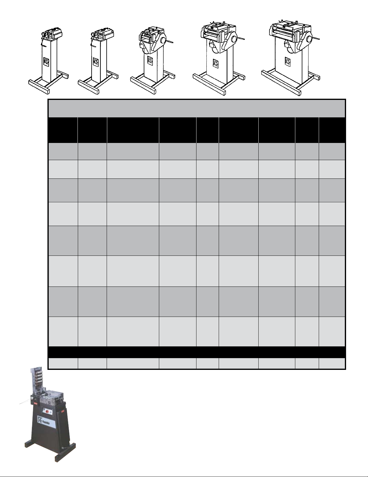
SA
Series
SB
Series
SpecificationS
SBX
Series
SCX
Series
SD
Series
Material Straightening Speed Rolls Rolls (2) Motor Power
Model Width Range per min Speed No., Dia. Dia. (HP) (vac/ph)
SA3 3” (76mm) .002” - .030” (.051-.76mm) 700” (1778cm) Standard 11, 3/8 (9.53mm) 1-1/2 (38.1mm) 1/4 115/1
SA3M 3” (76mm) .002” - .030” (.051-.76mm) 1,400” (3556cm) Medium 11, 3/8 (9.53mm) 1-1/2 (38.1mm) 1/2 115/1
SB4 4” (102mm) .003” - .050” (.076-1.27mm) 700” (1778cm) Standard 11, 5/8 (15.86mm) 1-1/2 (38.1mm) 1/2 115/1
SB4M 4” (102mm) .003” - .050” (.076-1.27mm) 1,400” (3556cm) Medium 11, 5/8 (15.86mm) 1-1/2 (38.1mm) 1/2 115/1
SBX4 4” (102mm) .004” - .080” (.10-2.03mm) 825” (2100cm) Standard 9, 7/8 (22.23mm) 1-3/4 (44.45mm) 3/4 115/1
SBX8 8” (203mm) .004” - .070” (.10-1.78mm) 825” (2100cm) Standard 9, 7/8 (22.23mm) 1-3/4 (44.45mm) 3/4 115/1
SBX12 12” (305mm) .004” - .060” (.10-1.52mm) 825” (2100cm) Standard 9, 7/8 (22.23mm) 1-3/4 (44.45mm) 3/4 115/1
SBX4M 4” (102mm) .004” - .080” (.10-2.03mm) 1,650” (4200cm) Medium 9, 7/8 (22.23mm) 1-3/4 (44.45mm) 1 115/1
SBX8M 8” (203mm) .004” - .070” (.10-1.78mm) 1,650” (4200cm) Medium 9, 7/8 (22.23mm) 1-3/4 (44.45mm) 1 115/1
SBX12M 12” (305mm) .004” - .060” (.10-1.52mm) 1,650” (4200cm) Medium 9, 7/8 (22.23mm) 1-3/4 (44.45mm) 1 115/1
SCX6 6” (152mm) .006” - .100” (.15-2.54mm) 825” (2100cm) Standard 9, 1-3/8 (34.93mm) 1-3/4 (44.45mm) 1 115/1
SCX12 12” (305mm) .006” - .090” (.15-2.29mm) 825” (2100cm) Standard 9, 1-3/8 (34.93mm) 1-3/4 (44.45mm) 1 115/1
SCX18 18” (457mm) .006” - .080” (.15-2.03mm) 825” (2100cm) Standard 9, 1-3/8 (34.93mm) 1-3/4 (44.45mm) 1 115/1
SCX24 24” (610mm) .006” - .065” (.15-1.65mm) 825” (2100cm) Standard 9, 1-3/8 (34.93mm) 1-3/4 (44.45mm) 1 115/1
SCX6M 6” (152mm) .006” - .100” (.15-2.54mm) 1,650” (4200cm) Medium 9, 1-3/8 (34.93mm) 1-3/4 (44.45mm) 2 230/1
SCX12M 12” (305mm) .006” - .090” (.15-2.29mm) 1,650” (4200cm) Medium 9, 1-3/8 (34.93mm) 1-3/4 (44.45mm) 2 230/1
SCX18M 18” (457mm) .006” - .080” (.15-2.03mm) 1,650” (4200cm) Medium 9, 1-3/8 (34.93mm) 1-3/4 (44.45mm) 2 230/1
SCX24M 24” (610mm) .006” - .065” (.15-1.65mm) 1,650” (4200cm) Medium 9, 1-3/8 (34.93mm) 1-3/4 (44.45mm) 2 230/1
SCX6H 6” (152mm) .006” - .080” (.15-2.03mm) 4,100” (10400cm) High 9, 1-3/8 (34.93mm) 1-3/4 (44.45mm) 3 230/1
SCX12H 12” (305mm) .006” - .070” (.15-1.78mm) 4,100” (10400cm) High 9, 1-3/8 (34.93mm) 1-3/4 (44.45mm) 3 230/1
SCX18H 18” (457mm) .006” - .060” (.15-1.52mm) 4,100” (10400cm) High 9, 1-3/8 (34.93mm) 1-3/4 (44.45mm) 3 230/1
SCX24H 24” (610mm) .006” - .055” (.15-1.40mm) 4,100” (10400cm) High 9, 1-3/8 (34.93mm) 1-3/4 (44.45mm) 3 230/1
Max Effective Max Straightening Pinch Drive Input
SD6 6” (152mm) .006” - .125” (.15-3.18mm) 825” (2100cm) Standard 9, 1-3/8 (34.93mm) 1-3/4 (44.45mm) 2 230/1
SD12 12” (305mm) .006” - .125” (.15-3.18mm) 825” (2100cm) Standard 9, 1-3/8 (34.93mm) 1-3/4 (44.45mm) 2 230/1
SD18 18” (457mm) .006” - .100” (.15-2.54mm) 825” (2100cm) Standard 9, 1-3/8 (34.93mm) 1-3/4 (44.45mm) 2 230/1
SD24 24” (610mm) .006” - .090” (.15-2.29mm) 825” (2100cm) Standard 9, 1-3/8 (34.93mm) 1-3/4 (44.45mm) 2 230/1
A right-to-left material ow direction is standard for above models –– left-to-right optional at no additional cost.
SC4 4” (102mm) .015” - .085” (.38-2.13mm) 825” (2100cm) Standard 9, 1-1/4 (31.75mm) 1-1/4 (31.75mm) 1 115/1
Model SC4 Straightener with individually adjustable upper
rolls. This 4” x .085” capacity straightener with its counterbalanced swing-open top is a Rapid-air original and
continues to be available due to customer acceptance and
demand. Dial-type indicators for roll settings are optional.
Model SC4
6
A NOTE ON ROLL DIAMETER AND QUANTITY:
The smaller the roll diameter in a straightener the better
it is able to remove distortions in the strip of material.
Rapid-Air straighteners are designed to optimize all
factors (including number of rolls, diameter and position)
within the published material capacities and specifications for each model.
Page 7

inStallation
Operating Instructions For Straighteners / Rapid Roll
Align the Rapid Roll with the feed allowing sufficient space for free stock
for the feed. The loop control arm
roller rests on the stock between the
Rapid Roll and the press. The Rapid
Roll should be bolted to the floor, especially when used to pull stock from
a non-powered reel.
The pinch rolls must be parallel in the
lateral (horizontal plane to insure that
there will be equal pinch force along
the full width of the stock). An upper
pinch roll adjustable eccentric trunion
is slotted with a locking screw in
its center. Adjust parallelism of the
rolls by loosening the center screw
and rotating the trunion through 180
degrees. A wide blade screwdriver
and allen wrench may be used. Use a
feeler gauge to check for equal spacing on either side of the pinch rolls.
Perform a visual check by lifting the
cover and placing a white piece of
paper in front of the pinch rolls to reflect light through the space between.
Tighten the pinch roll knob so the rolls
just touch. Observe the slit of reflected light between the rolls and make
any final adjustment. Tighten the
trunion lock screw. Raise the pinch
roll to allow clearance for the next
setup procedure.
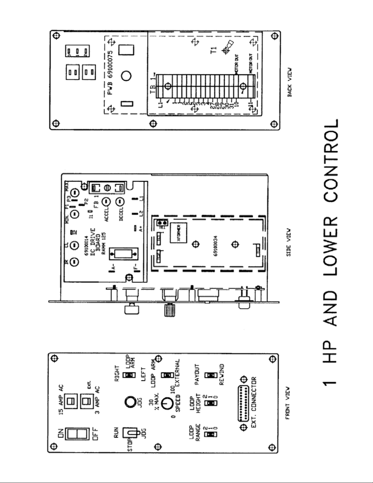
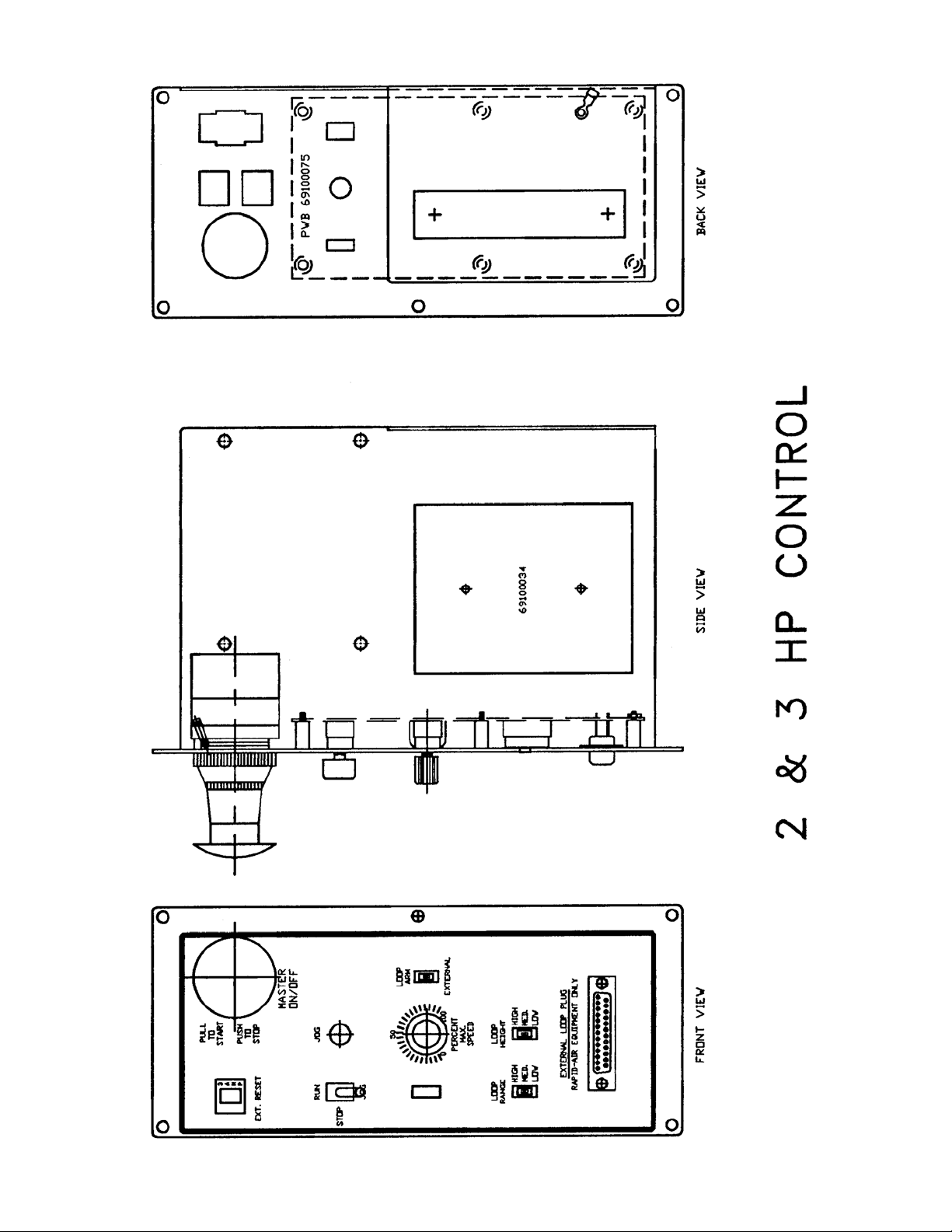
The main control unit is located behind
the side access cover. On pages 9 &
10 is an illustration of the layout of the
control panel. This diagram lists all
the components and the approximate
location of each that could be used for
troubleshooting the machine if a problem
should occur. The reel is shipped with
- 120 vac (1 phase) input. Visually check
all electrics before starting the reel.
7
Page 8

Start up procedure
Prior to applying power to the straightener, all the controls on the machine should be reviewed.
A brief summary is listed below.
Main Console And Controller
The main control console with controls is mounted on the cabinet of the
straightener. Located on the face of
the console are five switches, one potentiometer, one push-button and one
or two circuit breaker reset switches,
which are explained below.
1. ON/OFF SWITCH
This illuminated switch is the main
power switch for the controller.
On the 120 VAC straighteners, it
will be a toggle switch and on the
230 VAC version it will be a mushroom
push-button. It must be “ON” for the
straightener to function.
2. RESET BUTTONS (circuit breaker)
120 VAC.
a. 15 amp – This is the main circuit
breaker for the straightener.
b. 3 amp – This is the main circuit
breaker for the “D-SUB” (25 pin)
connector. Any shorting or overloads
would trip this breaker.
240 VAC.
a. 3 amp – This is the main circuit
breaker for the “D-SUB” connector.
Any shorting or overloads would trip
this breaker.
3. RUN/STOP/JOG
SELECTOR SWITCH
a. If “RUN” was selected and the
dancer control arm was raised, the
straightener rolls would rotate. If
“STOP” was selected then none of
the functions would work. If “JOG”
was selected then the jog button has
to be depressed to have the straightener rolls rotate.
4. JOG BUTTON
Used for intermittent movement of
the straightener rolls and mainly for
setup. The jog speed can be adjusted
by rotating the R3 potentiometer on
the 69100079 board in the control
sub panel.
5. % SPEED POTENTIOMETER
The % speed potentiometer adjusts
the maximum speed that the straightener rolls can rotate regardless
of the dancer arm height. It should be
set to maintain a constant material
feed rate through the straightener.
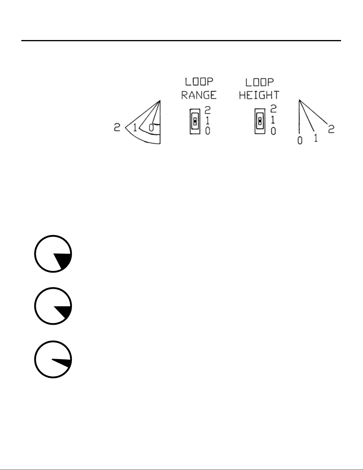
6. DANCER ARM LOOP HEIGHT
AND RANGE ADJUSTMENT
a. Loop Range – The loop range
switch adjusts the amount of
travel that the dancer arm will
move to provide the full range of
speed on the straightener. It has
three positions with a “0” as the
least travel from slowest to
fastest speed and a “2” has the
most movement between slowest
to fastest speed.
b. Loop Height – The loop height
switch is used for setting the
start position of the control arm.
It has three positions with the “0”
setting having the start position at
the dancer arm rest position and
the “2” having the start position
somewhat higher than the dancer
arm rest position. This setting will
determine the dancer arm angle
that the reel will start turning. This
function is used to accommodate
different thickness of material which
would have a different bend radius
thus requiting the dancer arm to
be at a height somewhat above the
home position when at rest.
7. LOOP ARM / EXTERNAL SWITCH
This switch is used to select whether
the material loop is controlled by the
dancer arm or an external loop control. If LOOP ARM is selected then the
control will monitor the dancer arm
movement. If EXTERNAL is selected
then the control will monitor whatever
is plugged into the “D-SUB” (25 pin)
connector.
8. REMOTE INTERFACE
PORT “D” CONNECTOR
This 25 pin connector, located on the
lower portion of the console is used
to communicate with external loop
equipment. The RSB, RTB, & RTA will
plug into the port and can immediately
be implemented.
CAUTION: Never plug any type of
computer or non Rapid-Air equipment
into this plug or severe damage could
result. Always consult the factory
when installing different external
controls for advice on compatibility
and wiring information.
9. PANEL MOUNTED ELECTRICAL
COMPONENT DESCRIPTION
69100034 board – proportional control
board
69100076 board – component interface board
69100014 board – (RAMM) D.C. motor
control board [120 VAC, 1 PH]
69100038 board – (RAMM) D.C. motor
control board [240 VAC, 1 PH]
8
Page 9
9
Page 10
10
Page 11
dancer arm loop
Dancer Arm Loop Height Adjustment
Three different loop sensing
arm operating positions are
selected manually during set-up.
By selecting the higher number,
the zero point of the dancer arm
is raised from its rest position to
the angle shown (as indicated
0-2). The dancer arm will move
from rest position to the angle
selected before the straightener
rolls begin to rotate.
Dancer Arm Loop Range Function
30 degree — Loop sensing arm travels through a full 30 degree arc to vary
3
2
1
rotation speed from slow to full speed as controlled by % speed pot.
20 degree —Loop sensing arm travel through a 20 degree arc to vary
speed from slow to full speed as controlled by % speed pot.
10 degree — Loop sensing arm travels through a 10 degree arc to vary
rotation speed from slow to full speed as controlled by % speed pot.
11
Page 12

Standard Straightener componentS
Curve Up/Down Adjustment
Some applications have dies that cannot accept anything but flat stock and
other dies run better with the material curving up or down to miss the built in
edge required in the die. Before this feature was added, operators would
under straighten or over straighten the material to suit their needs but in doing
so would severely change the material entering the die. This not only caused
feeding problems but part quality problems. With this feature, curve up or down
can be accomplished by changing the position of the rolls without stressing
the material.
optional Straightener componentS
Entrance Cascade Roll
The entrance cascade roll assembly
is used to maintain a support arc for
stock entering a feed. The cascade
roll has three extra rollers to help the
material flow better.
Exit Cascade Roll
The straightener is shipped with
the exit side pre-drilled for the
cascade roll or guide roll block.
The entrance and exit use the
same components.
Entrance Guide Roll Block
All straighteners are shipped with an
entrance guide roll. This contains a
roller and two adjustable edge guides.
Angle Bracket
Rapid-Air offers this accessory that
mounts between the straightener
head and the base. It angles the
exit side of the straightener twelve
degrees lower than the entrance
side. This feature works very well
when using the straightener to pull
off a non-powered reel.
12
Page 13

operation
Once the straightener has been
tested and all the functions work,
then it should be tested for what it
was designed to do and that is to
remove coil set.
Retract all of the idler rolls and the
exit pinch roll to a position so when
the cover is closed the material is
not being deformed. Open the cover
of the straightener and position the
edge guides for maximum width. Cut
and place about a four foot length of
the material onto the straightener
rolls with the exit end of the material extending through the exit pinch
rolls and centered from side to side
in the straightener. Close the cover
and latch it. Adjust the exit pinch roll
enough to grip and hold the material.
Adjust the edge guides so that they
just touch the material.
Adjust the first idler roll knob, this is
the one nearest the entrance of the
straightener, so that it deforms the
material no more than the thickness
of the material. Adjust the second
idler roll knob so it is lightly on the roll.
Run the material to check that the exit
pinch roll is not slipping on the material, readjust if necessary. This piece
will still have coil set in the first two
feet of the material as it was not run
through the complete straightening
cycle. At this time, this piece could be
rerun and checked for straightness or
a new piece could be cut and run and
then be checked.
A good check is to guide the exiting
material, keeping it parallel to the rolls,
until the run is complete and then hold
one end of the material in the air while
peering down the length of the material. If the material still has “coil set”
then readjust roll pressure on the last
roll, towards the exit end but before the
pinch roll, until the material is straight.
Run one or more short length setups
while making final adjustments. Once
the proper setting has been determined, the quick release top maintains
the adjustment during loading.
Thread the material from the reel
through the straightener, under the
dancer arm, and into the pulling
device leaving ample loop between
the straightener and the pulling
device. If the material thickness is
such that when exiting the straightener, it will not let the dancer arm
down to the rest position, then
either lengthen the dancer arm
or adjust the loop height until the
straightener stops feeding.
Set the % speed potentiometer
to 50% for a starting position and
start the pulling device to have the
material feeding. If the straightener
gets finished and stops before
material is needed again then
the straightener is set to feed too
fast, slow it down by adjusting
the % speed potentiometer. The
ideal straightening is to have the
straightener slightly exceed the
feed rate required. This minimizes
the starting and stopping and
resultant stock deformation.
maintenance
Lubrication
Gear transmission
The reservoir oil capacity is about
4 oz. The reservoir oil should be
changed every 2000 hours and should
be filled to the oil level site gauge.
Use MOBILE 600W cylinder oil or
equivalent. This is a non-synthetic oil.
Rolls
Although the rolls should be cleaned
periodically they never have to
be greased as all the rolls have
permanently lubricated bearings.
13
Drive belt
At the oil change interval, check for
belt tension and wear.
Page 14

troubleShooting guide
MAIN SWITCH ON BUT NOT LIT
1. CB tripped.
a. Reset CB.
2. Unit not plugged into main power.
a. Plug into main power source.
3. No power in incoming line.
a. Check outlet.
b. Check power cord.
4. Loose wiring.
a. Check terminals and connections.
MOTOR CREEPS IN STOP POSITION
1. R1 & R3 pot on 69100034 board not
correctly adjusted.
a. Readjust pots so rollers stop.
Call factory.
UNIT TURNS BUT WON’T JOG
1. Selector switch not in jog position.
a. Select jog.
2. Jog pot on 69100076 board not
adjusted correctly.
a. Adjust pot. Call factory
3. Maximum speed pot on Ramm
board set too low.
a. Adjust pot.
UNIT ON BUT MOTOR WON’T RUN.
(ARMATURE VOLTAGE PRESENT –
ON RAMM BOARD)
1. Check motor wiring and fuse.
a. Replace motor cord and correct
motor wiring. Call factory.
2. Check motor.
a. Worn brushes or motor
defective. Call factory.
UNIT ON BUT MOTOR WON’T RUN.
(NO ARMATURE VOLTAGE ON
RAMM BOARD)
1. Selector switch not in run
position.
a. Turn selector switch to
run position.
2. If running with a dancer arm
control.
a. Check that the external/loop
switch is in the loop arm position.
3. If running with external control.
a. Check that the external/loop
arm switch is in the
external position.
4. Height switch setting too high.
a. Set height setting to “0”.
5. Percent speed pot set too low.
a. Adjust percent speed
pot to 100%.
6. Fuses blown.
a. Check fuses & circuit breaker.
7. No AC voltage at DC drive board.
a. Check wiring.
8. Check Signal voltage between
P2 to I2 on DC drive.
0-6 VDC—Ramm
0-9 VDC—Regen Drive
while moving dancer arm.
a. If there is a signal, check
continuity between I1 & I2.
b. If no continuity, replace D.C.
drive or call factory.
9. Check line voltage input of
69100034 board, 120 VAC, TB-1.
a. Check wiring. Call factory.
10. Check pico fuse 69100034
board (f1).
a. Replace fuse, 1 amp pico
fuse — call factory.
11. Check for 0-12 VDC between
pin #1 (=V) and pin #2 (GND)
of panduit connector TC3 on
board #69100034.
a. If no voltage present, call
factory.
12. Check for DC voltage between
pin #6 (VO) and pin #2 (GND) of
panduit connector TC3, on board
69100034, while moving the dancer
arm from minimum to maximum
position.
a. If voltage is present, turn power
off and check the ribbon cable
connections between panduit
connector #TC3 of 69100034
board and panduit connector
#TB-4 of 69100076 board. This
should be a continuity check for
tight connections. Call factory
for assistance.
b. If voltage is not present move
on to step 13.
13. Check voltage between pin #5 of
TB-6 & pin #3 of TB-5 on 69100076
board while moving the dancer
arm from minimum to maximum
position.
a. If voltage varies 2.5-4 volt from
minimum to maximum position,
the dancer arm pot is OK, but
the 69100076 board could be
defective. Call factory.
b. If voltage does not vary when
moving the dancer arm from
minimum to maximum
position — call the factory
for assistance.
14
Page 15

69100034 taut StocK output
The 69100034—Proportional control
board has a taut stock output. The
output must be wired to a solid state
relay as the max current draw is 20
MA. The solid state relay’s contact
can then be incorporated into the
electrical control circuitry.
The output can be wired so that
the relay is either on or off with the
dancer arm down. When the dancer
arm reaches the set point for taut
stock, the relay switches state.
The taut stock height set point is set
by raising the dancer arm to a position that the material is taut and then
adjusting pot R7 so the output changes state. Lower and raise the dancer
arm a few times to check that the set
point repeats and then the set point
repeats and then the task is finished.
The potentiometer that is located just
below the taut stock terminal strip is
used for presetting the max voltage
output requirement for a particular
drive. A RAMM DC drive needs
6 VDC for max motor speed so turn
the pot fully counter clockwise.
A minarik drive board needs 10 VDC
for max motor speed so turn the
pot fully clockwise.
The following is a brief wiring diagram
for the taut stock.
3
GRD
2
10 VDC out with dancer arm down
1
0 VDC out with dancer arm down
15
Page 16

Safety warning – pleaSe read carefully
RAMM Solid State DC Motor Speed Control
This product should be installed and
serviced by a qualified technician,
electrician or electrical maintenance
personnel familiar with its operation
and the hazards involved. Proper installation (see instruction information
which accompanies product), which
includes wiring, mounting in proper
enclosure, fusing or other overcurrent
protection and grounding, can reduce
the chance of electrical shocks, fires
or explosion in this product or products used with this product, such
as electric motors, switches, coils
solenoids and/or relays. Eye protec
tion must be worn when working with
control under power. This product is
constructed of materials (plastics,
metals, carbon, silicon, etc.) which
may be a potential hazard. Individual
material safety data sheets (MSDS)
are available upon request. Proper
shielding, grounding and filtering of
-
this product can reduce the emission
of radio frequency interference (RFI)
which may adversely affect sensitive
electronic equipment. If information is
required on this product, contact our
factory. It is the responsibility of the
ultimate user of this product to read
and comply with this safety warning.
(SW effective 1/89)
***IMPORTANT***
YOU MUST READ THESE
INSTRUCTIONS BEFORE
OPERATING CONTROL
1. Be sure AC line voltage
corresponds to control voltage.
TABLE 1: NOMINAL TRIMPOT SETTINGS
MIN (minimum speed): 15% CL (current limit/torque): 65%
MAX (maximum speed): 65% ACCEL (acceleration start): 20%
IR (IR compensation): 25% DECEL (deceleration stop): 20%
2. Install the correct Plug-In
Horsepower Resistor according
to armature voltage and motor
horsepower.
3. Recheck connections: AC line to
L1 and L2; armature to A+ and
A– and field (Shunt motors only
to F+ and F-.) (
in improper direction, interchange
armature leads.)
4. Install proper AC line fuse and
armature fuse as required.
5. Nominal trimpot settings are as
follows (expressed in % of full
CW rotation):
Note: If motor runs
Plug-In Horsepower Resistor
A Plug-In Horsepower Resistor
must be installed
to match the
RAMM to the
motor horsepower and voltage. See table 2
for the correct
value. Plug-In
Horsepower
Resistors are
stocked by your
distributor.
TABLE 2: PLUG-IN HORSEPOWER RESISTOR CHART*
MOTOR HORSEPOWER RANGE **
Armature Voltage
90-130 VDC
1/4
1/2
3/4
1***
* Motor horsepower and armature voltage must be specified when ordering so that proper resistor will be supplied.
** For overlapping motor horsepower range use lower value Plug-In Horsepower Resistor.
*** Auxiliary heat sink must be used to achieve HP rating.
Armature Voltage
180 VDC
1/2
1
1-1/2
2***
16
Plug-in
Horsepower
Resistor Resistance
Value (ohms)
.05
.025
.015
.01
Rapid-Air
Part Number
69100529
69100530
69100534
69100531
Page 17

introduction
RAMM Full Wave Solid State DC Motor Speed Control
The RAMM Full Wave Solid State DC
Motor Speed Control represents the
latest state of the art design achievable through modern technology.
FEATURES INCLUDE:
Integrated Circuitry
Used to control and amplify
command and reference levels
with both closed and open loop
feedback to provide superior
motor regulation. (Speed changes
due to load, line voltage, or
temperature variations are held to
minimum levels).
High Quality Components
Selected and tested for proven
dependability.
3. Follow the recommended supply
wire sizes as per table 3.
4. Follow the NEC and other
electrical codes that apply.
TABLE 3: MINIMUM SUPPLY WIRE SIZE REQUIREMENTS
Max.
Motor
Amps
(DC Amps)
6.0
12.0
16.0
* Maximum recommended wire size.
Max.
Motor
HP
90V
1/2
1
1-1/2
Max.
Motor
HP
180V
1
2
3
CAUTION: SEPARATE BRANCH
PROTECTION MUST BE PROVIDED
ON 240V CIRCUITS.
5. Connect control in accordance
to connection diagram.
Max.
Motor
Run
16
14
12
Minimum
Wire Size (AWG)
Cu only
Max. Motor Run
14
12*
12
Transient Protection
Used to prevent failure of the
power bridge circuit caused by
voltage spikes on the AC line.
High Reliability
When used in accordance with
instructions in this manual, the
RAMM will provide years of
trouble free operation.
A. INITIAL SETUP AND WIRING
General Instructions
1. Install proper size Plug-In
Horsepower Resistor (see table 2).
2. The RAMM can be connected
to a standard 120V or 240V
50/60 Hz AC line (be sure the
AC input voltage corresponds
to the control voltage rating and
the motor rating). (e.g. 90-130 VDC
motor on 120VAC and 180 VDC
motor on 240 VAC).
FIGURE 1: BASIC RAMM CONNECTION DIAGRAM
CAUTION: DO NOT BUNDLE
POTENTIOMETER CONNECTIONS
(P1, P2, P3) AND INHIBIT
CONNECTIONS (I1, I2) WITH
AC LINE OR MOTOR WIRES.
B. VOLTAGE FOLLOWING
All models can be controlled with an
isolated analog reference voltage
(0-6VDC) in lieu of the main speed
potentiometer. The voltage is connected to P2 (+) and F-. The control
output voltage will linearly follow the
input voltage. The source impedance
of the input should be 10K ohms or
less. The Min trimpot can be used to
provide an offset speed. If an offset is
not required, adjust the Min to 0+ or
0– speed as desired. The Max trimpot
is rendered inoperative in the voltage
following mode. Use auxiliary trimpot
to limit the control range. If the input
signal is not isolated, or is a current
signal (4-20 MA), the RASI240D Signal
Isolator must be used. It will allow
direct connection to process controllers and microprocessors.
17
Page 18

introduction (cont.)
CAUTION:
1. The voltage feeding P2 and
F– must be isolated from the AC
line. Do not ground P2 or F– to set
up a zero ground reference.
2. Do not bundle signal wires to P2
and F– with AC line motor
connections. If signal wires are
over 18”, use shielded cables.
C. FUSING
The RAMM has provision for a built
in AC line fuse and armature fuse.
The AC line fuse protects the control
against catastrophic failure– if the
fuse blows, the control is miswired,
the motor is shorted or grounded, or
the RAMM control is defective. The
armature fuse provides overload
protection for the motor and control.
Choose the proper size armature fuse
by multiplying the maximum DC motor
amps by 1.7. On domestic 240 Volt
AC lines, separate branch circuit
protection for each line must be
used. All fuses should be normal blow
ceramic 3AG or ABC or equivalent.
1. AC Line Fuse is chosen according
to the maximum rating of the
control:
– 12 AMP fuse for all motors up
to 3/4 HP-90V and 1-1/2 HP 180VDC.
– 25 AMP fuse for all motors 1
and 1-1/2 HP-90V and 2 and
3 HP-180VDC.
(Use Buss ABC, Littlefuse
326 ceramic fuse or equivalent.)
TABLE 4: ARMATURE FUSE CHART
Horsepower
90 VDC
Motor
1/4
1/2
3/4
1
1-1/2
* Also used as AC line fuse.
Horsepower
180 VDC
Motor
1/2
1
1-1/2
2
3
2. Armature Fuse can be chosen
in accordance with the fuse chart.
Note: The armature fuse is
calculated based on the
approximate full load DC current
rating of the motor times a form
factor of 1.5. If motor has
characteristics not consistent
with these approximations, a
different fuse value may have to
be used. Fuses are available from
your distributor.
Approx.
DC Motor Current
(Amps)
2.5
5.0
7.5
10.0
15.0
Fuse
Rating
(AC Amps)
4
8
12*
15
25*
18
Page 19

adjuStmentS and control functionS
RAMM Adjustments And Control Functions
WARNING: If adjustments are made
under power, insulated adjustment
tools must be used and eye protection
must be worn.
The RAMM has been factory adjusted
to provide 0-full speed using the
speed control knob. Minimum and
Maximum speed trimpots are provided to change the speed from other
than 0-full speed. The Acceleration
(ACCEL) trimpot is provided to allow
for a smooth start over an adjustable
time period each time the AC power is
applied or the speed pot is rotated.
The DECEL trimpot controls the amount
of ramp-down when the speed pot
is adjusted to a lower speed. The
Current Limit (CL, or torque output)
adjustment is factory set to approximately 1-1/2 times the motor rating.
The IR Compensation (IR) is factory
adjusted to provide excellent motor
regulation under normal operation.
NOTE: In order for the IR comp and
CL trimpot settings to be correct, the
proper Plug-in Horsepower Resistor
must be installed for the particular
motor and input voltage being used.
Do not attempt to change the settings
of the trimpots unless absolutely
necessary since they are factory
adjusted to near optimum settings.
The following procedure, presented in
order of adjustment sequence, should
be used when readjusting all trimpot
functions.
FIGURE 2: ACCEL/DECEL
Trimpot ADJUSTMENT
Acceleration Start. The ACCEL
A.
is factory set at approximately
.2 seconds. To readjust to
different times, set the knob to the
desired position as indicated in Fig 2.
Deceleration. The DECEL is
B.
factory set to provide a ramp down time of .2 seconds. To
change the ramp-down time,
adjust the DECEL trimpot as
indicated in Fig 2.
Minimum Speed Adjustment. If a
C.
higher than zero minimum speed
is desired, readjust the minimum
speed by turning the speed control
knob to zero setting (full CCW
position). Then adjust the Min.
Speed trimpot to the desired setting.
NOTE: The min. speed adjustment
will affect the max. speed setting.
Therefore, it is necessary to readjust
the max. speed after the min. speed is
adjusted.
D. Maximum Speed Adjustment. Turn
Speed Control Knob to full speed
(maximum CW position). Adjust max.
speed trimpot to new desired setting.
NOTE: Do not attempt to adjust the
max. speed above the rated motor
RPM since unstable motor operation
may occur. For moderate changes in
the max. speed, there will be a slight
effect on the min. speed setting.
E. Current Limit (CL/Torque Adjust-
ment). CL circuitry is provided to
protect the motor and control
against overloads. The CL also limits
the inrush current to safe level
during startup. The CL is factory
set to approximately 1.5 times the
full load rating of the motor. (CL
trimpot is nominally set to ap-
proximately 65% of full CW rotation).
To set the CL to factory specifications
adjust as follows:
1. Set speed control knob at approxi mately 30-50% CW rotation. Set CL
trimpot to full CCW position.
2. Connect a DC ammeter in series
with the armature lead.
3. Lock shaft of motor (be sure CL
pot is in full CCW position).
Apply power and rotate CL pot CW
slowly until DC ammeter reads 1.5
times motor rating (do not exceed 2
times motor rating, Max. CW position.)
NOTE: If only an AC ammeter is available, it can be installed in series with
the AC line. Follow above instructions;
however, set AC amperage at .75
times motor rating.
IR Compensation Adjustment. IR
F.
compensation is provided to sub stantially improve load regulation.
If the load presented to the motor
does not vary substantially, the
IR adjustment may be set at a
minimum level (approximately 1/4
of full setting). The control is
factory adjusted to approximately
3% regulation. If superior perfor mance is desired (less than 1%
speed change of base speed
from 0 to full load), then the IR
comp. Should be adjusted as follows:
NOTES: 1. Excessive IR comp. will
cause control to become unstable,
which causes motor cogging.
2. For tach feedback applications the
IR comp can be set to minimum rota
tion (full CCW).
1. Set IR comp. trimpot at approxi mately 25% of CW rotation. Run
motor unloaded at approximately
1/3 speed and record RPM.
2. Run motor with maximum load and
adjust IR comp. trimpot so that
the motor speed under load equals
the unloaded speed per step 1.
3. Remove load and recheck
unloaded RPM. If unloaded RPM
has shifted, repeat procedure for
more exact regulation.
The RAMM is now compensated to
provide minimal speed change under
large variations of applied load.
-
19
Page 20

warranty
Limited Warranty – RAMM 125, 225, 225D
For a period of one (1) year from date of original purchase Rapid-Air Corporation will repair or replace without charge
devices which our examination proves to be defective in material or workmanship. This warranty is valid if the unit has not
been tampered with by unauthorized persons, misused, abused or improperly installed and has been used in accordance
with the instructions and/or ratings supplied. The foregoing is in lieu of any other warranty or guarantee expressed or
implied, and we are not responsible for any expense (including installation and removal), inconvenience, or consequential
damage, including injury to any person, caused by items of our manufacture and/or sale. Some states do not allow certain
exclusions or limitations found in this warranty so that they may not apply to you. In any event, Rapid-Air Corporation’s total
liability, under all circumstances, shall not exceed the full purchase price of this unit.
20
Page 21

Wiring Diagram for STD Speed Straighteners (1-HP)
21
Page 22

Wiring Diagram for High Speed Straighteners (3-HP)
22
Page 23

Wiring Diagram for Medium Speed Straighteners (2-HP)
23
Page 24

Standard Speed SBX Series 4” Straightener
24
Page 25

Standard Speed SBX Series 4” Straightener
25
Page 26

Standard Speed SBX Series 4” Straightener
26
Page 27

Standard Speed SBX Series 4” Straightener
27
Page 28

SCX-6 Straightener Standard Speed
28
Page 29

SCX-6 Straightener Standard Speed
29
Page 30

SCX-6 Straightener Standard Speed
30
Page 31

SCX-6 Straightener Standard Speed
31
Page 32

SCX-6 Straightener Standard Speed
32
Page 33

SCX-6 Straightener Standard Speed
33
Page 34

Typical Stamping Layout
34
Page 35

Straightener Sa3 - Sb4
OPERATION
For set up only, place a short length
of stock about four feet on the
bottom rolls, between the pinch rolls.
Set the entrance guide rolls before
lowering the cover. Make sure the
top rolls are retracted to prevent
stock deformation. Apply light pinch
roll force on the stock to insure
adequate assisting pulling force on
the stock and to prevent slippage of
the stock over the straightener rolls.
Never overload the pinch rolls. This
could damage the stock by extrusion
causing permanent deformation.
With the cover down and the stock in
place, position the idler rolls such that
they are mid-way between the drive
rolls. The windows in the side of the
cover are visual indicators of the idler
rolls relative position to the drive rolls.
Do not lock the cover down at this
time. With the cover held down firmly
by hand, lower the vertical entrance
knob until the first idler roll contacts
the stock with only slight deformation
(crease) at the station. Observe the
degree of deformation at this first station by lifting the cover and noting the
pattern of light reflecting off the stock
surface. Rotate the vertical entrance
knob 1/4 turn down and lock in place.
Close the cover, hand hold in place
while lowering the exit knob. Continuously observe the changing deformation pattern until all but the last station
reflects a change. The stock should
reflect a diminishing deformation
pattern until the final set of exit rolls
afford no deformation. Lock the exit
knob. Close the cover and latch.
The dancer arm position for height
and range is operator selectable
through the settings of thumbwheels.
The speed of the straightener rollers
is automatically controlled by the
position of the dancer arm. As the
dancer arm is raised, the straightener rollers increase in speed. This
minimizes starting and stopping and
resultant stock deformation.
CAUTION: Lateral adjustment, generally, requires no more than two or three
turns either side of center. Never
force idler rolls against the powered
rolls. This will deform the stock.
CAPACITY
The model SA3 is designed for 3”
maximum width and .005 to .020
thick material. The SB4 is designed
for 4” maximum width and .007 to
.035 thick material. The maximum
feed rate for SA3 and SB4 is 700
inches per minute. The maximum
feed rate for SAM3 and SBM4 is
1400 inches per minute.
ELECTRIC MOTOR
SA3 and SB4 straighteners are
furnished with a 1/4 HP - 2500 RPM
permanent magnet motor. Input
power is single phase, 115 volt A.C.
rotation must be CW as viewed from
shaft end. SAM3 and SBM4 have
a 1/2 HP motor.
35
Page 36

Straightener Sa3 - Sb4
Lubrication
Gear transmission oil - Use Mobil 2000 SSU 100 degree F 600W cylinder oil or equivalent.
SA3 & SB4 Worm Gear Case (above motor) 4 oz. capacity.
SA3 Spur Gear Case (straightener side) 4 oz. capacity.
SB4 Spur Gear Case (straightener side) 6 oz. capacity.
Change oil every 1000 hours.
1. Loop Control Arm
2. Pinch Roll Knob
3. Eccentric Trunion
4. Cover Latch
5. Exit Adjustment Knob
6. Entrance Adjustment Knob
7. Visual Indicator Window
8. Lateral Adjustment Knob
9. Entrance Guide Rolls
36
Page 37

rapid roll
OPERATION
For set up only, place a short length
of stock about four feet long on the
bottom rolls, between the pinch
rolls. Set the entrance guide rolls
to maintain stock position. Make
sure the top rolls are retracted. To
prevent stock deformation apply
light pinch roll force on the stock
to insure adequate assisting
pulling force on the stock and to
prevent slippage of the stock while
operating. Never overload the pinch
rolls. This could damage the stock
by extrusion causing permanent
deformation.
The dancer arm position for height
and range is operator selectable
through the setting of thumbwheels.
The speed of the Rapid Roll rollers is
automatically controlled by the position of the dancer arm.
As the dancer arm is raised the Rapid
Roll rollers increase in speed. This
minimizes starting and stopping and
resultant stock deformation.
CAPACITY
The model P1V is designed for 1.5”
maximum width and .0005 to .075 thick
material. The P4V is designed for 4”
maximum width and .0005 - .060 thick
material. The P8V is designed
for 8” maximum width and .0005 - .050
thick material. The maximum feed rate
for P1V, P4V & P8V is 700 inches per
minute. The maximum feed rate for
P1M-P8M is 1400 inches per minute.
ELECTRIC MOTOR
P1V, P4V, and P8V Rapid Rolls
are furnished with a 1/4 HP 2500 RPM permanent magnet
motor. Input power is single
phase, 115 volt A.C. Rotation
must be clockwise as viewed
from shaft end. The P1M, P4M &
P8M have a 1/2 HP motor.
LUBRICATION
Gear transmission oil – Use
Mobil 2000 SSU, 100 degree F 600 W
cylinder oil or equivalent. Rapid Roll
worm gear case (above motor) 4 oz.
capacity (fill to level plug). Change
every 1000 hours of operation.
GREASE FITTINGS
Use Mobilux number 2 or equivalent.
37
Page 38

1. Loop Control Arm
2. Pinch Roll Knob
3. Grease Zircs
4. Eccentric Trunion
5. Entrance Guide Rollers
6. D.C. Drive Motor
38
 Loading...