

Page 1

PALLET MASTER (PMDH)
OPERATING INSTRUCTIONS
MODELS
(INCLUDES PMDH35 & PMDH50. 115VAC, 1PH, 60HZ)
RAPID-AIR CORPORATION
4601 KISHWAUKEE ST. • ROCKFORD, IL 61109-2925
Phone: (815) 397-2578 • Fax: (815) 398-3887 • Web Site: www.rapidair.com
Page 2
OPERATING INSTRUCTIONS PMD HORIZONTAL
(Revision )
10/1/2002
Warning!!!
Taut Stock (over travel reset) not connected.
Check wiring schematic to connect interface with material pulling device.
INSTALLATION
1. The machine that you have just received is fully assembled and ready to be put into position. Due to shipment vibration the machine should be checked to be sure all screws and
bolts are tight and that all electrical components are in place inside cabinet. Visually inspect the machine for damaged parts due to shipment. If the machine was damaged in shipment, contact the carrier first to report the damage, and then Rapid-Air.
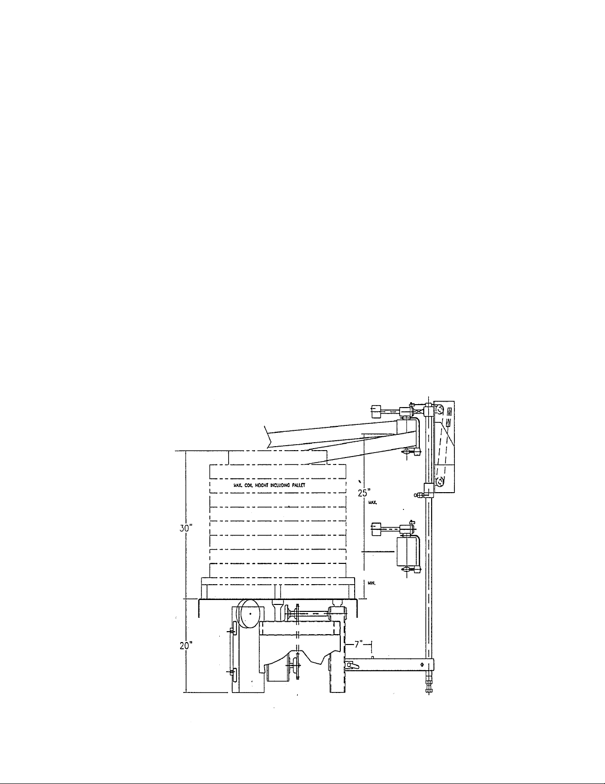
2. Install the machine on a level surface with sufficient clearance for loading and unloading
coils.
3. The machine is completely self-contained and need only be plugged into a 20 amp, 120 volt,
60 HZ outlet. If an extension cord is used as the source to the machine, it should be a minimum #12 gauge wire to keep the voltage loss down and for electrical safety reasons.
See Drawing Below
2
Page 3
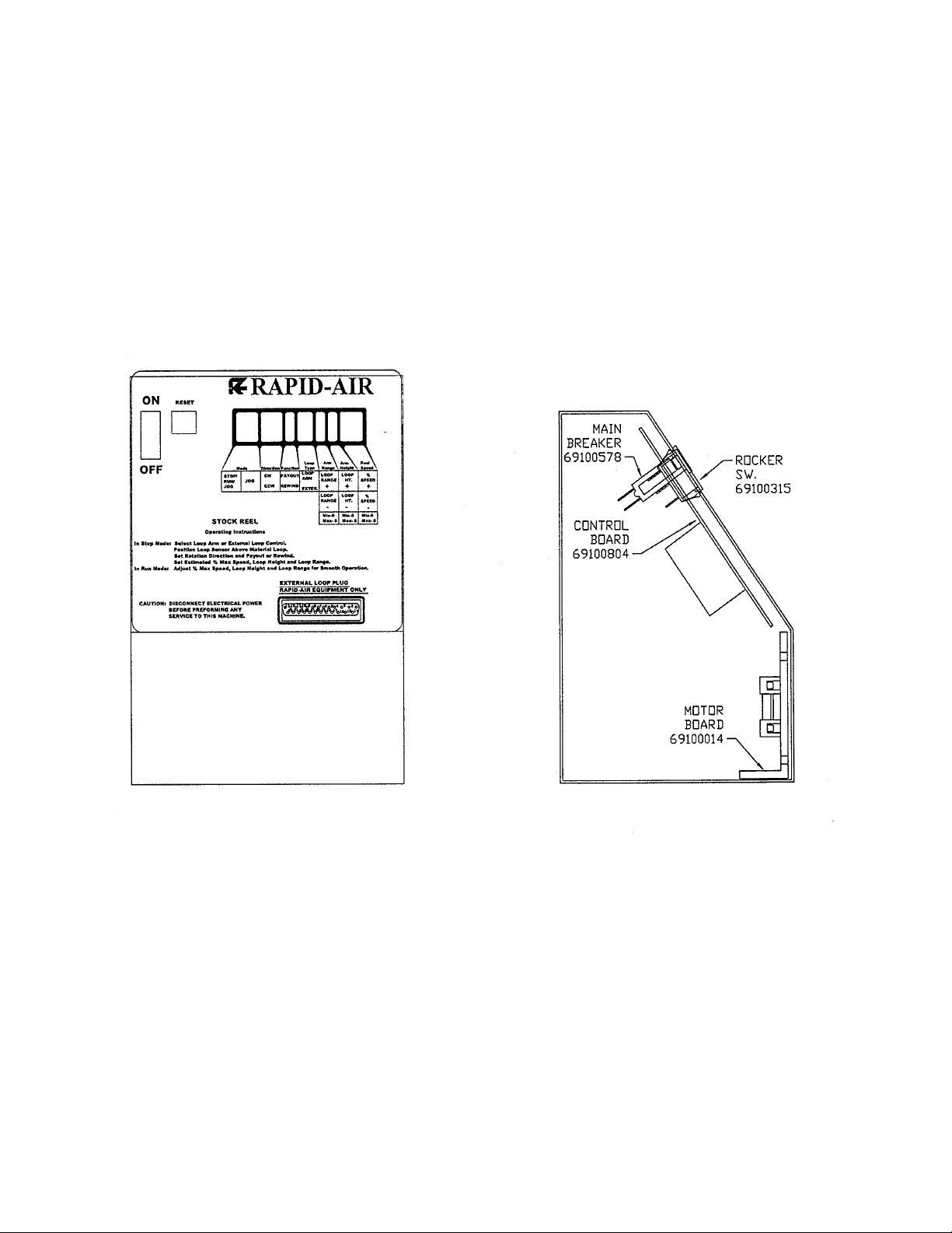
The main control unit is located behind the pushbutton cover. Below is an illustration of the
layout of the control panel. This diagram lists all the components and the approximate location
of each that could be used for troubleshooting the machine if a problem should occur. The reel
is shipped with—120 VAC (1 phase) input. Visually check all electrics before starting the reel.
3
Page 4
Mechanical Operating Procedure
To Load or Unload a Coil Ring
The PMD can handle any coils that are on a pallet, table diameter is 42 inches for the PMD-35
and 51 inches for the PMD-50 and max 3500 lbs on a PMD-35 and MAX 5000 lbs on a PMD
50, but only up to 30 inches in height from the table top.
Step 1:
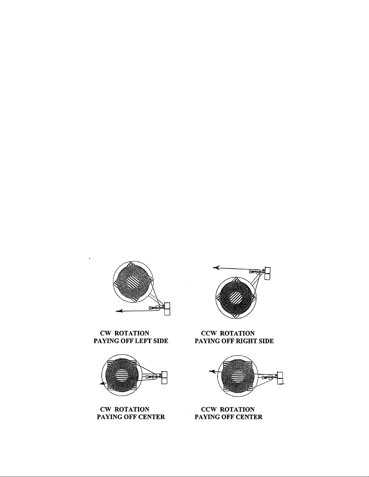
Decide if the material that is paying out will go over the table or beside the table and which side
of the table. If all the coils are wrapped the same way then choose a side that will be in line
with the press and don’t forget the ease of loading of the pallets. If the coils are wrapped so the
table direction has to be switched to unwind the next coil then over the top will be best otherwise the PMD will have to be moved to pay off the other side as the material flow is the opposite way.
Step 2:
Make sure the arm is clear of the loading zone and load the pallet onto the table. Align the pallet so it is in the center of the table. Adjust the dancer arm roller assembly so that it is even
with or slightly above the coil that is being unwound. Jog the table around so the end is within
reach from the operator station and stop. Cut the material free and grab the loose end and then
jog the table around so the material can be threaded in behind the roller. When there is sufficient material available, the PMD can be put into “run” and as the material is walked to the material work station the PMD will rotate and keep up.
.
4
Page 5

Setting up the control
Turn on the main power switch and select “LH” for loop arm horizontal at “Loop Type” on
the pushbuttons.
Turn off the main power switch, press and hold the “Run/Stop/Jog” button while turning the
main power switch on. The first screen you see will display the jog speed percentage.
_________________________________
| JOG SPEED 23% + |
| NEXT - |
|_________________________________|
If you want the jog speed faster then press the “Reel Speed “+ “ “ pushbutton. If you want
the jog speed slower then press the “ Reel Speed “-” “ pushbutton. The jog speed is shown
in percent of max jog speed. If the jog speed is “OK “ then push the Run/Stop/Jog button
once for next.
The next screen asks if you want to set up the sensor? As before the percent speed buttons
are used for the yes-no. Select “yes”! And then next.
_________________________________
| SETUP SENSOR YES |
| NEXT NO |
|_________________________________|
The next screen asks you to set the low set point. If the dancer arm is at “No Material
Rest” then just save the setting by pushing the Stop/Run Jog pushbutton.
_________________________________
| SENSOR LOW SETPOINT |
| SAVE XXX |
|_________________________________|
The next screen is to set the offset of the program. Potentiometers are hard to get set from
left to right so we built in an offset. If you set the low and high range and go into run and
the reel runs for no reason then an offset has to be put in. Go through the setup procedure
again and put in an offset of –3 to –5 and now the pot is zero.
_________________________________
| LOW OFFSET +0 + |
| NEXT - |
|_________________________________|
5
Page 6

You have now set the dancer arm limits.
The next screen is to exit the setup and start working.
_________________________________
| EXIT SETUP? YES |
| NO |
|_________________________________|
Choose yes and next and the next screen appears.
_________________________________
| SHUT OFF POWER TO |
| SAVE AND EXIT |
|_________________________________|
The dancer arm is now ready for production running.
.
6
Page 7
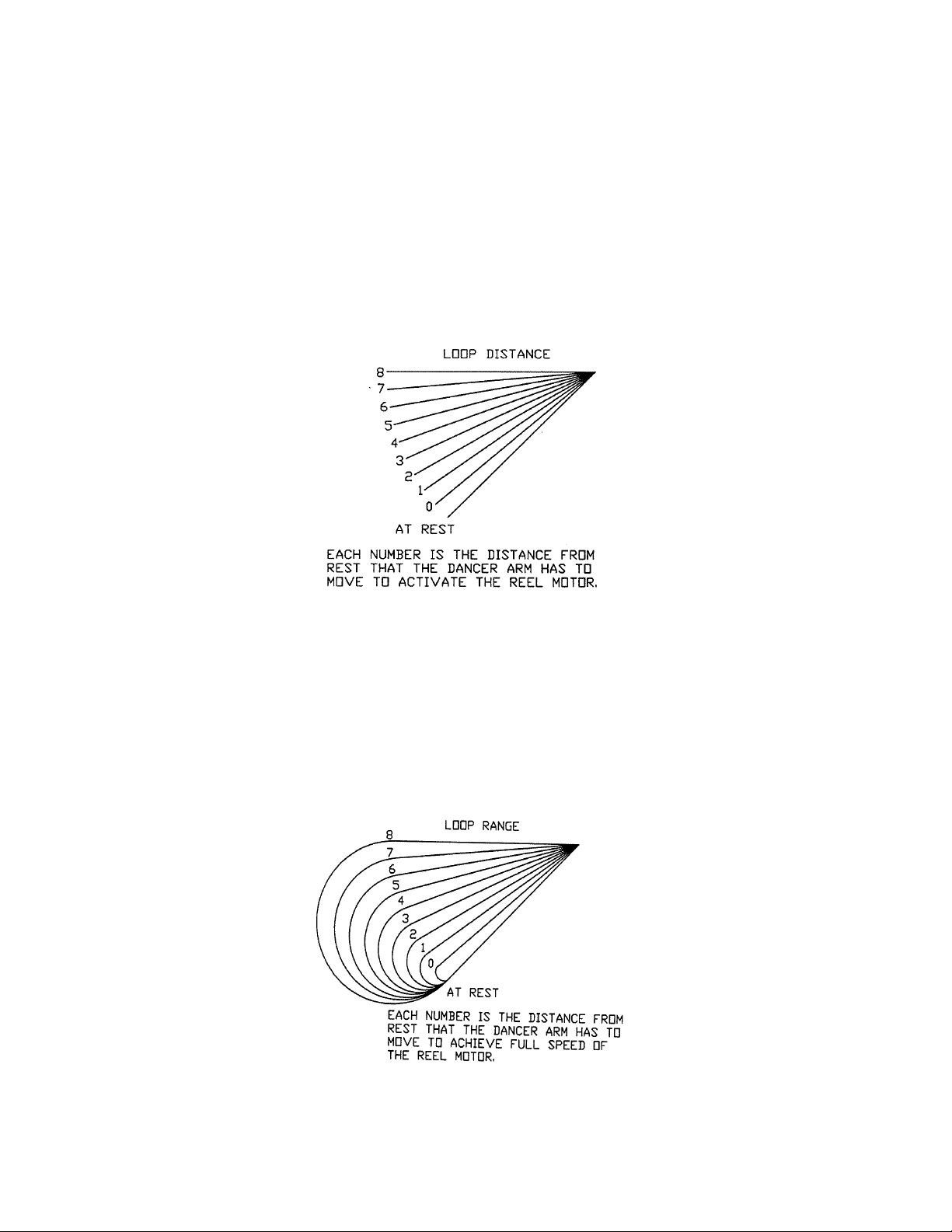
DANCER ARM LOOP POSITION ADJUSTMENT
Eight different loop sensing arm operating positions can be selected during set-up. The material thickness determines the dancer arm rest position. Once the material is threaded up and
the material is resting on the dancer arm and the reel runs in the rest position then select a
higher number on the height adjustment until the reel stops rotating. The zero point of the
dancer arm is moved from it’s no material rest position to the current rest position shown (as
indicated 0-8). The dancer arm will start the material dereeling from the new rest position selected. The function is active and can be changed in the run mode.
DANCER ARM LOOP RANGE FUNCTION
The loop range function selects the degree of arm movement to achieve maximum motor
speed selected. If a loop range of “0” was selected then the arm would only have to move approximately 1/2 inch to have the reel at full speed whereas if the loop range “8” was selected
then the arm would have to move almost the full travel or approximately 41/2 inches to get to
full speed. The function is active and can be changed in the run mode.
7
Page 8

START UP PROCEDURE
Prior to applying power to the machine the operator should review all the controls on the machine. A brief summary of the controls is listed below.
MAIN CONSOLE & CONTROLLER
The main pushbutton control box is mounted next to the dancer arm pot on the control arm assembly. Located on the face of the console are eleven pushbuttons, one display, one on/off
switch, one circuit breaker, one external loop plug and inside the box is motor board and one
potentiometer when required, all of which are explained below.
1. DIRECTIONAL CONTROL - (CW/CCW) -
The direction control function selects the direction the reel will turn, clockwise or counterclockwise. To find which way it should be programmed, Look at how the coil is wound and decide which way the coil should unwind, clockwise or counter-clockwise. Push the appropriate
button until the correct rotation is displayed on the display. CW= clockwise & CCW= counterclockwise.
2. % SPEED POT - The % speed function adjusts the maximum speed that the reel will rotate
and should be set to maintain a constant feed rate. Adjustable in the run mode.
3. ON/OFF SWITCH - This illuminated switch is the main power switch for the controller. It
must be “ON” for the machine to function.
4. PAYOUT/REWIND - The payout/rewind function selects whether the dancer arm will
cause the reel to function at a low speed at the home position and increase the reel speed as the
arm extends (Payout); or cause the reel to function at a low speed at the extended position and
increase the reel speed as the arm retracts. (Rewind).
5. RUN/STOP/JOG - This function selects between Run, Stop & Jog. If in Run and the con-
trol arm is moved the coil plate will turn. If in Jog, the Jog button has to be depressed for the
coil plate to turn. If in Stop, There should be no movement of the coil plate even if the dancer
arm is raised or lowered or the jog pushbutton is pressed.
6. JOG BUTTON - Used for intermittent movement of material on the coil plate, mainly for
set up or rewinding excess material. Active in jog mode only.
7. DANCER ARM LOOP HEIGHT & RANGE ADJUSTMENT -
a. Loop Range - The loop range function adjusts the amount the dancer arm will travel to pro-
vide the full range of speed of the reel. There are eight positions available.
b. Loop Height - The loop height function is used for setting the start position of the control
arm. The setting determines when the reel will start turning. Each position will move the operating start position up from the home position to accommodate specific material rest position
requirements.
8
Page 9

8. LOOP ARM/EXTERNAL SWITCH
This switch selects either dancer arm (internal) by displaying “LV” for loop arm vertical reel or
“LH” for loop arm horizontal reel (PMD) or external loop control by displaying “RT” for the
RTB and ”RS” for the RS_1. The RLL will work on the “RT” selection.
The external connection for a remote loop control on the PMDH usually isn’t used as there is
not much of a loop to look at for adjusting the motor speed.
9. RESET BUTTONS
A. 15 amp - This is the main circuit breaker for the reel.
10. REMOTE INTERFACE PORT “D” CONNECTOR
This connector is used to communicate with external loop control equipment if used.
CAUTION: Never plug any type of computer or non Rapid-Air equipment into
this plug or severe damage will result. Always consult with the factory when installing new external controls for compatibility and wiring information.
ELECTRICAL COMPONENT DESCRIPTION
69100804 board - main reel control board
69100014 (RAMM) - D.C. motor board
69100218 dancer arm potentiometer
69100578 circuit breaker
69100315 rocker switch
9
Page 10

PMDH SPECIFICATIONS AND MAINTENANCE
CAPACITY
SERIES 35 50
COIL CAPACITY 3500 LBS 5000 LBS
STANDARD STOCK WIDTH 4” 6”
MAX MATERIAL THICKNESS .062 .062
TABLE O.D. 42” 51”
MAX COIL OD 36” 50”
MAX SPEED 33 RPM 20 RPM
MAX COIL HEIGHT 30” 30”
ELECTRIC MOTORS
PMDH 35 IS furnished with 3/4 hp, 2500 rpm permanent magnet D.C. motor.
PMDH 50 IS furnished with 1 hp, 2500 rpm permanent magnet D.C. motor.
All motors are 90 V.D.C. unless otherwise specified.
All brushes on the motors should be checked every 1500 to 2000 hours.
LUBRICATION
Gear transmission oil - Use Mobil 600W cylinder oil or equivalent. Fill to bottom edge of the
oil fill hole. The oil capacity of the gear box is as follows:
PMDH 35 32 oz.
PMDH 50 32 oz.
The oil should be changed every 1000 hours.
10
Page 11

TROUBLE SHOOTING GUIDE
MAIN SWITCH ON BUT NOT LIT
1. CB tripped
a. Reset CB
2. Unit not plugged into main power.
a. Plug into main power source.
3. No power in incoming line.
a. Check outlet.
b. Check power cord.
4. Loose wiring
a. Check terminals and connections.
MOTOR CREEPS IN STOP POSITION
1. “Min” speed pot on RAMM board out of adjustment.
UNIT TURNS BUT WON’T JOG
1. Jog function was not selected
a. Select jog.
2. Jog speed has not been set up
a. Call factory.
UNIT ON BUT MOTOR WON’T RUN. (ARMATURE VOLTAGE PRESENT - ON
RAMM BOARD)
1. Check motor wiring
a. Replace motor cord or correct motor wiring. Call factory.
2. Check motor
a. Worn brushes or motor defective. Call factory.
b. Check for oil in motor, gear box seal could have ruptured.
.
UNIT ON BUT MOTOR WON’T RUN. (NO ARMATURE VOLTAGE ON RAMM
BOARD)
1. Selector switch not in run position.
a. Turn selector switch to run position.
2. If running with a dancer arm control.
a. Check that the external/loop arm function is in the loop arm position.
3. If running with external control.
a. Check that the external/loop arm function is in the external position.
4. Loop height switch setting too high.
a. Set height setting to “0”.
5. Taut stock switch has been tripped.
a. Reset the switch on the dancer arm
11
Page 12

6. Percent speed function set too low.
a. Adjust percent speed function to 100%.
7. Fuses blown.
a. Check fuses & circuit breaker.
8. No AC voltage at DC drive board.
a. Check wiring.
9. Check Signal voltage between P2 to P1 on DC drive.
0-6 VDC—Ramm
0-9 VDC—Regen Drive
while moving dancer arm.
a. If there is a signal, check continuity between I1 & I2.
If no continuity, replace D.C. drive or call factory.
10. Check pico fuse on 69100804 board (F1).
a. Replace fuse, 1 amp pico fuse—call factory.
12
Page 13

RAPID-AIR CORPORATION
RAMM
SOLID STATE
DC MOTOR
SPEED CONTROL
SAFETY WARNING—PLEASE READ CAREFULLY
This product should be installed and serviced by a qualified technician, electrician or electrical
maintenance personnel familiar with its operation and the hazards involved. Proper installation
(see instruction information which accompanies product), which includes wiring, mounting in
proper enclosure, fusing or other over current protection and grounding, can reduce the chance
of electrical shocks, fires or explosion in this product or products used with this product, such
as electric motors, switches, coils solenoids and/or relays. Eye protection must be worn when
working with control under power. This product is constructed of materials (plastics, metals,
carbon, silicon, etc.) which may be a potential hazard. Individual material safety data sheets
(MSDS) are available upon request. Proper shielding, grounding and filtering of this product
can reduce the emission of radio frequency interference (RFI) which may adversely affect sensitive electronic equipment. If information is required on this product, contact our factory. It is
the responsibility of the ultimate user of this product to read and comply with this safety warning. (SW effective 1/89)
***IMPORTANT***
YOU MUST READ THESE INSTRUCTIONS BEFORE OPERATING CONTROL
1. Be sure AC line voltage corresponds to control voltage.
2. Install the correct Plug-In Horsepower Resistor according to armature voltage and motor
horsepower.
3. Recheck connections: AC line to L1 and L2; armature to A+ and A– and field (Shunt motors only to F+ and F-.) (Note: If motor runs in improper direction, interchange armature
leads.)
4. Install proper AC line fuse and armature fuse as required.
5. Nominal trim pot settings are as follows (expressed in % of full CW rotation):
TABLE 1: NOMINAL TRIM POT SETTINGS
MIN (minimum speed): 15% CL (current limit/torque): 65%
MAX (maximum speed): 65% ACCEL (acceleration start): 20%
IR (IR compensation): 25% DECEL (deceleration stop): 20%
13
Page 14

PLUG IN HORSEPOWER RESISTOR
A Plug-In Horsepower Resistor must be installed to match the RAMM to the motor horsepower
and voltage. See table 2 for the correct value. Plug-In Horsepower Resistors are stocked by
your distributor.
TABLE 2. PLUG IN HORSEPOWER RESISTOR CHART*
* Motor horsepower and armature voltage must be specified when ordering so that proper resistor will be supplied.
** For overlapping motor horsepower range use lower value Plug-In Horsepower Resistor.
*** Auxiliary heat sink must be used to achieve HP rating.
MOTOR
HORSEPOWER RANGE **
Armature
Voltage
90-130 VDC
1/4
1/2
3/4
1***
Armature
Voltage
180 VDC
1/2
1
1-1/2
2***
Plug-in
Horsepower
Resistor
Resistance
Value (ohms)
.05
.025
.015
.01
Rapid-Air
P/N
69100529
69100530
69100534
69100531
14
Page 15

INTRODUCTION
The RAMM Full Wave Solid State DC Motor Speed Control represents the latest state of the
art design achievable through modern technology.
Features Include:
Integrated Circuitry
Used to control and amplify command and reference levels with both closed and open loop
feedback to provide superior motor regulation. (Speed changes due to load, line voltage, or
temperature variations are held to minimum levels).
High Quality Components
Selected and tested for proven dependability.
Transient Protection
Used to prevent failure of the power bridge circuit caused by voltage spikes on the AC line.
High Reliability
When used in accordance with instructions in this manual, the RAMM will provide years of
trouble free operation.
A. Initial Setup and Wiring
General Instructions
1. Install proper size Plug-In Horsepower Resistor.
(see table 2)
2. The RAMM can be connected to a standard 120V or 240V 50/60 Hz AC line (be
sure the AC input voltage corresponds to the control voltage rating and the motor rat
ing). (e.g. 90-130 VDC motor on 120 VAC and 180 VDC motor on 240 VAC)
3. Follow the recommended supply wire sizes as per table 3.
4. Follow the NEC and other electrical codes that apply.
CAUTION: SEPARATE BRANCH PROTECTION MUST BE PROVIDED ON 240V
CIRCUITS.
5. Connect control in accordance to connection diagram.
TABLE 3. MINIMUM SUPPLY WIRE SIZE REQUIREMENTS
*Maximum recommended wire size
MAX.
MOTOR
AMPS
(DC AMPS)
6.0
12.0
16.0
MAX.
MOTOR
HP
90V
1/2
1
1 1/2
MAX.
MOTOR
HP
180V
1
2
3
MINIMUM WIRE SIZE
(AWG) Cu only
MAX. MAX.
MOTOR MOTOR
RUN RUN
16 14
14 12*
12 12
15
Page 16

Fig. 1. Basic RAMM Connection Diagram
CAUTION: Do not bundle potentiometer connections (P1, P2, P3) and inhibit
connections (I1, I2) with AC line or motor wires.
B. VOLTAGE FOLLOWING. All models can be controlled with an isolated analog reference voltage (0-6 VDC) in lieu of the main speed potentiometer. The voltage is connected to
P2 (+) and F-. The control output voltage will linearly follow the input voltage. The source impedance of the input should be 10K ohms or less. The Min trim pot can be used to provide an
offset speed. If an offset is not required adjust the Min to 0+ or 0– speed as desired. The Max
trim pot is rendered inoperative in the voltage following mode. Use auxiliary trim pot to limit
the control range. If the input signal is not isolated, or is a current signal (4-20ma), the RASI240D) Signal Isolator must be used. It will allow direct connection to process controllers and
microprocessors.
CAUTION: 1. The voltage feeding P2 and F– must be isolated form the AC line.
Do not ground P2 or F– to set up a zero ground reference.
2. Do not bundle signal wires to P2 and F– with AC line motor
connections. If signal wires are over 18”, use shielded cables.
C. FUSING. The RAMM has provision for a built in AC line fuse and armature fuse. The AC
line fuse protects the control against catastrophic failure– if the fuse blows, the control is miswired, the motor is shorted or grounded, or the RAMM control is defective. The armature fuse
provides overload protection for the motor and control. Choose the proper size armature fuse
by multiplying the maximum DC motor amps by 1.7. On domestic 240 Volt AC lines, separate
branch circuit protection for each line must be used. All fuses should be normal blow ceramic
3AG or ABC or equivalent.
1. AC Line Fuse is chosen according to the maximum rating of the control:
12 AMP fuse for all motors up to 3/4 HP-90 VDC and 1 1/2 HP-180 VDC.
25 AMP fuse for all motors 1 and 1 1/2 HP-90 VDC and 2 and 3 HP-180 VDC.
16
Page 17

1. AC Line Fuse is chosen according to the maximum rating of the control:
12 AMP fuse for all motors up to 3/4 HP-90 VDC and 1 1/2 HP-180 VDC.
25 AMP fuse for all motors 1 and 1 1/2 HP-90 VDC and 2 and 3 HP-180 VDC.
(Use Buss ABC, Littlefuse 326 ceramic fuse or equivalent.)
2. Armature Fuse can be chosen in accordance with the fuse chart. Note: The armature fuse is
calculated based on the approximate full load DC current rating of the motor times a from
factor of 1.5. If motor has characteristics not consistent with these approximations, a different fuse value may have to be used. Fuses are available from your distributor.
TABLE 4. ARMATURE FUSE CHART
90VDC 180VDC
MOTOR MOTOR
HORSEPOWER
1/4 1/2
1/2 1
3/4 1 1/2
1 2
1 1/2 3
APPROX.
DC MOTOR
CURRENT
(AMPS)
2.5
5.0
7.5
10.0
15.0
FUSE
RATING
(AC AMPS)
4
8
12*
15
25*
*Also used as AC line Fuse.
ADJUSTMENTS AND CONTROL FUNCTIONS
WARNING: If adjustments are made under power, insulated adjustment
tools must be used and eye protection must be worn.
The RAMM has been factory adjusted to provide 0-full speed using the speed control knob.
Minimum and Maximum speed trim pots are provided to change the speed from other than 0full speed. The Acceleration (ACCEL) trim pot is provided to allow for a smooth start over an
adjustable time period each time the AC power is applied or the speed pot is rotated. The DECEL trim pot controls the amount of ramp-down when the speed pot is adjusted to a lower
speed. The Current Limit (CL, or torque output) adjustment is factory set to approximately 1
1/2 times the motor rating. The IR Compensation (IR) is factory adjusted to provide excellent
motor regulation under normal operation.
17
Page 18

NOTE: In order for the IR comp and CL trim pot settings to be correct, the proper Plug-in
Horsepower Resistor must be installed for the particular motor and input volt age
being used. Do not attempt to change the settings of the trim pots unless absolutely
necessary since they are factory adjusted to near optimum settings.
The following procedure, presented in order of adjustment sequence, should be used when readjusting all trim pot functions.
Fig 2. ACCEL/DECEL
TRIM POT ADJUSTMENT
A. Acceleration Start. The ACCEL is factory set at approximately .2 seconds. To readjust to
different times, set the knob to the desired position as indicated in Fig 2.
B. Deceleration. The DECEL is factory set to provide a ramp-down time of .2 seconds. To
change the ramp-down time, adjust the DECEL trim pot as indicated in Fig 2.
C. Minimum Speed Adjustment. If a higher than zero minimum speed is desired, readjust
the minimum speed by turning the speed control knob to zero setting (full CCW position).
Then adjust the Min. Speed Trim pot to the desired setting.
NOTE: The min. speed adjustment will affect the max. speed setting. Therefore, it is
necessary to readjust the max. speed after the min. speed is adjusted.
D. Maximum Speed Adjustment. Turn Speed Control Knob to full speed (maximum CW position). Adjust max. speed trim pot to new desired setting.
NOTE: Do not attempt to adjust the max. speed above the rated motor RPM since unstable motor operation may occur. For moderate changes in the max. speed, there will be a
slight effect on the min. speed setting.
E. Current Limit (CL/Torque Adjustment). CL circuitry is provided to protect the motor
and control against overloads. The CL also limits the inrush current to safe level during startup.
The CL is factory set to approximately 1.5 times the full load rating of the motor. (CL trim pot
is nominally set to approximately 65% of full CW rotation).
18
Page 19

To set the CL to factory specifications adjust as follows:
1. Set speed control knob at approximately 30-50% CW rotation.
Set CL trim pot to full CCW position.
2. Connect a DC ammeter in series with the armature lead.
3. Lock shaft of motor (be sure CL pot is in full CCW position).
Apply power and rotate CL pot CW slowly until DC ammeter reads 1.5 times motor
rating (do not exceed 2 times motor rating, Max. CW position.)
NOTE: If only an AC ammeter is available, it can be installed in series with the AC line.
Follow above instructions; however, set AC amperage at .75 times motor rating.
F. IR Compensation Adjustment. IR compensation is provided to substantially improve load
regulation. If the load presented to the motor does not vary substantially, the IR adjustment
may be set at a minimum level (approximately 1/4 of full setting). The control is factory
adjusted to approximately 3% regulation. If superior performance is desired (less than 1%
speed change of base speed from 0 to full load), then the IR comp. Should be adjusted as
follows:
NOTES: 1. Excessive IR comp. will cause control to become unstable, which causes
motor cogging.
2. For tach feedback applications the IR comp can be set to minimum rotation
(full CCW).
1. Set IR comp. trim pot at approximately 25% of CW rotation. Run motor unloaded at approximately 1/3 speed and record RPM.
2. Run motor with maximum load and adjust IR comp. trim pot so that the motor speed under
load equals the unloaded speed per step 1.
3. Remove load and recheck unloaded RPM. If unloaded RPM has shifted, repeat procedure
for more exact regulation.
The RAMM is now compensated to provide minimal speed change under large variations of
applied load.
19
Page 20

LIMITED WARRANTY—RAMM 125, 225, 225D
For a period of one (1) year from date of original purchase Rapid-Air Corporation will repair or replace
without charge devices which our examination proves
to be defective in material or workmanship. This warranty is valid if the unit has not been tampered with by
unauthorized persons, misused, abused or improperly
installed and has been used in accordance with the instructions and/or ratings supplied. The foregoing is in
lieu of any other warranty or guarantee expressed or
implied, and we are not responsible for any expense
(including installation and removal), inconvenience, or
consequential damage, including injury to any person,
caused by items of our manufacture and/or sale. Some
states do not allow certain exclusions or limitations
found in this warranty so that they may not apply to
you. In any event, Rapid-Air Corporation’s total liability, under all circumstances, shall not exceed the
full purchase price of this unit.
20
Page 21

21
 Loading...