

Page 1

mini-servo feed
oPerATinG insTrUCTions
MODELS
MS SERIES
(INCLUDES MS2, MS4 & MS8. 115VAC, 1PH, 60HZ)
RAPID-AIR CORPORATION
4601 KISHWAUKEE ST. • ROCKFORD, IL 61109-2925
Phone: (815) 397-2578
• Fax: (815) 398-3887 • Web Site: www.rapidair.com
1
Page 2

TAble of ConTenTs
INTRODUCTION .......................................................................................................................................... pg. 3
INSTALLATION ............................................................................................................................................ pg. 4
ROLL PRESSURE ......................................................................................................................................... pg. 4
ROLL RELEASE HANDLE ............................................................................................................................ pg. 4
ELECTRIC PILOT RELEASE ......................................................................................................................... pg. 4
GEAR BOX .................................................................................................................................................... pg. 4
PILOT RELEASE STOP ................................................................................................................................ pg. 5
FEED ROLLS.................................................................................................................................................. pg. 5
ADJUSTABLE ENTRANCE GUIDE ............................................................................................................ pg. 5
OPERATOR INPUT SECTION ..................................................................................................................... pg. 6-7
TROUBLESHOOTING .................................................................................................................................. pg. 8-9
PRECAUTIONS AND SAFETY .................................................................................................................... pg. 10
WARRANTY ................................................................................................................................................. pg. 11
MINI-SERVO PARTS ASSEMBLY DRAWING ......................................................................................... pg. 12-13
MINI-SERVO CONTROL ASSEMBLY DRAWING ................................................................................... pg. 14
MINI-SERVO ENVELOPE DRAWING ........................................................................................................ pg. 15
MS2 SERVO ADJUSTABLE MOUNTING BRACKET DIMENSIONS ..................................................... pg. 16
KEYPAD DIMENSIONS .............................................................................................................................. pg. 17
MINI-SERVO FEED WIRING SCHEMATIC ............................................................................................... pg. 18
2
Page 3
inTrodUCTion
Rapid-Air Introduction to MS-Series
The MS-Series servo has many
features found in the more expensive
models. Some of its features are:
Input:
120 VAC, 50/60 Hz
Amperage required at input:
10 amps maximum
Accuracy:
.0025 per feed length at the rolls
Maximum feed length input:
999.999 inches
Job storage:
99 jobs
Display:
4 rows by 80 characters, backlit
Note:
Fault type:
Displayed on the drive if a fault
occurs otherwise an “8.” is
displayed.
Rolls:
Hardened and ground.
Drive roll parallelism adjustment:
Used to tune the rolls to the
material if needed.
The Rapid-Air MS-Series feed uses
the same type of programming
procedures as it has in its more expensive models. Input a feed length,
strokes per minute, and a feed arc
and the program will adjust the servo
acceleration/deceleration and maximum servo speed parameters to the
requirement needed to keep up to the
press strokes per minute.
The precision mechanical roll feed has
been designed for compactness, ease
of setup and installation. A 120 VAC
receptacle is all that is required of the
customer. Two cables are supplied with
the control and need to be connected to
the proper locations of the motor. The
electrical controls are housed in a small
box that can be mounted on the press
or if purchased, on a post that can be
positioned close to the press.
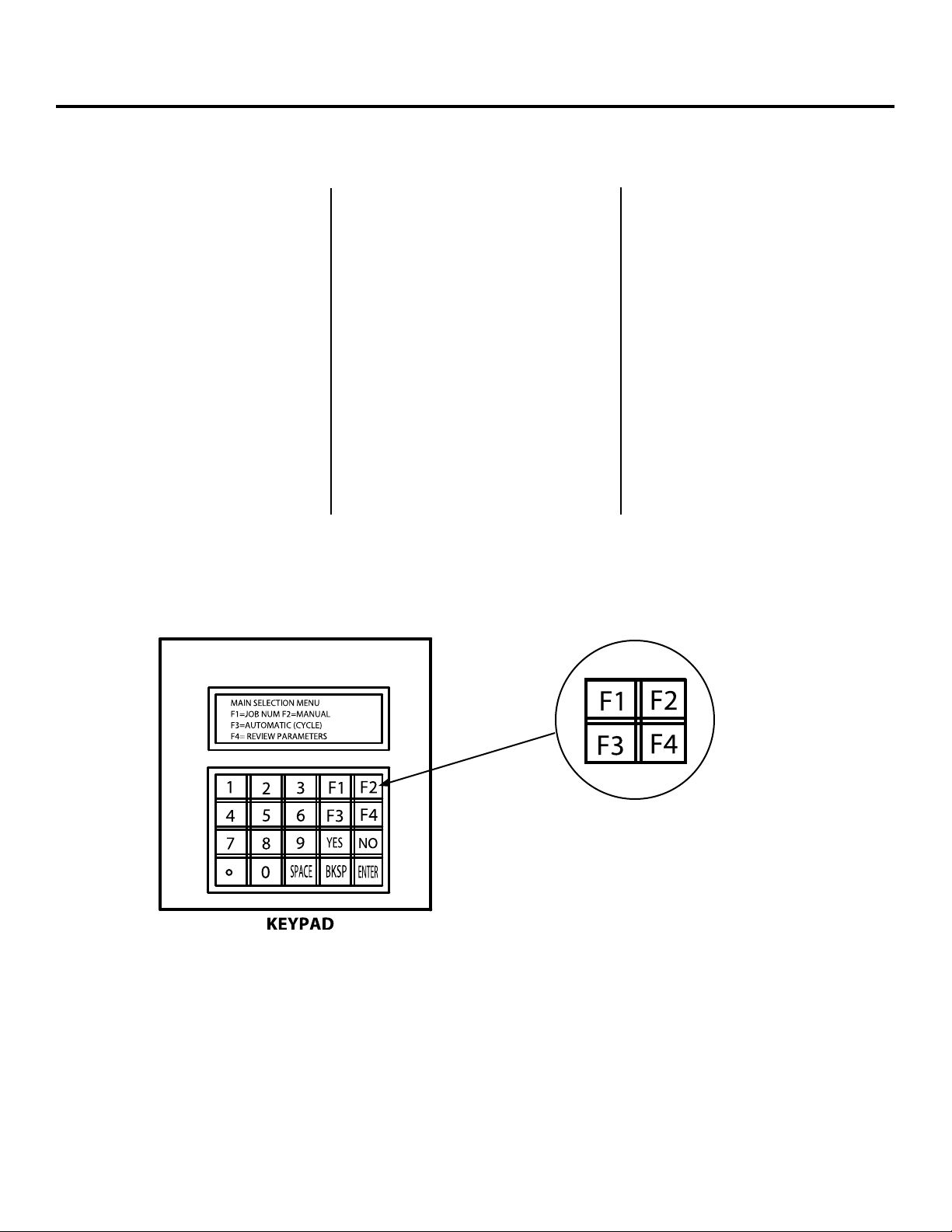
4 keys were chosen to have a double meaning,
arrows and “F” keys. The arrows were brought out
as the primary instead of the “F” keys. If you would
bear with us, we are looking at a correction.
3
Page 4

insTAllATion, roll PressUre & releAse, PiloT releAse
Installation
The Rapid-Air servo was run and fully
tested before being shipped from our
plant. Carefully inspect all parts when
uncrating them. If you find any damaged parts, please report it to the carrier that delivered the servo drive and
at the same time, report the damage to
your distributor.
The servo feed container should
contain:
1) servo feed – standard
1) console – standard
Roll Pressure
The roll pressure knob is located on the
entrance side of the feed and is a knurled knob with a locking nut located
right behind it. It is positioned parallel
to the inlet face and uses a compression spring for adjusting roll pressure.
1) console stand – optional
1) servo mounting bracket – optional
1) cascade roller assembly – optional
Please contact someone at your
facility to verify what options you
purchased.
If a mounting bracket was purchased,
then it should be mounted first
being careful that the center line of the
bracket lines up with the centerline of
the die area. The servo can then be
mounted on the bracket. A print of the
bracket can be found in the back of
this manual.
If a bracket was not purchased,
then the servo will have to be mounted
on the press bed or customer
provided bracket. Line up the rolls
to be centered and perpendicular
to the center line of the die area.
Included in the back of this manual
is a hole pattern layout print for the
MSA2 servo.
Roll Release Handle
The roll release handle is located on the side of the feed. Lifting the handle
opens the rolls and lifting to its stop will lock the rolls in place. This is a true
statement if the pilot release stop is not set. If the stop is set, then the roll will
only raise until the stop is reached just like in automatic for pilot release.
Gear Box
The gear box is located within the
feed body on the same side as the
roll release handle. It has a nonlubricated gear box so it is essentially
maintenance free.
Electric Pilot Release
The optional electric pilot release can be mounted on the entrance side of the
servo at the place labeled “inlet.” It is the customer’s responsibility to interface
the pilot release valve with the customer supplied, press-mounted, activating
switch. The air requirements for the release to work correctly is 80 to 120 psi,
dry filtered and lightly lubricated air. There should be a minimum of 2 CFM
available at all times.
4
Page 5

feed rolls, PiloT releAse sToP, enTrAnCe GUide
Feed Rolls
The rolls are case hardened and
ground solid rolls which make them
good for profiling, if you are running
a part that would need clearances
ground into the roll. Useful information that you might need in the future
is that one revolution of the rolls is
3.173 inches. This can be used to
check if the program and motor are
working correctly. Put a line on the
lower roll and program the feed to
feed to feed 3.173 inches. The line
should return to the same spot after
every feed. If it does not, then call
Rapid-Air. If it does, then something
in the setup, such as roll pressure
or an obstruction in the die, could
cause a short feed.
Pilot Release Stop
A pilot release stop may be added for higher speeds. The pilot release stop is
mounted next to the roll pressure knob and should be set to let the rolls open
about .005/.010 to free the material during piloting.
Adjustable Entrance Guide
The adjustable entrance guide is an add-on feature that can and should be used
on the entrance and exit of the servo feed. It has screwdriver slotted adjustable
stops for quick stop adjustment. By having one on each end of the feed, the set-up
time for aligning the material in the feed is decreased considerably as you will
now know that the material is straight through the feed before entering the die.
5
Page 6

oPerATor inPUT seCTion
Operator Input Section
The intent of this section is to familiarize the operator with the flow of the
program and what to expect with each
key press. Each program screen of
the servo will be displayed and also
comments to clarify possible questions.
There are four sections that will be
explained and they are as follows:
SECTION 1 —
JOB NUMBER
SECTION 2 —
MANUAL MODE
SECTION 3 —
AUTOMATIC MODE
SECTION 4 —
REVIEW JOB PARAMETERS
When the servo is first started, and
has performed its startup procedure,
the first screen displayed should look
like this:
MAIN SELECTION MENU
F1=JOB NUM F2=MANUAL
F3=AUTOMATIC (CYCLE)
F4=REVIEW PARAMETERS
*SELECT F1=JOB NUM
The first step in programming a job is
to select a two digit job number which
will be used to store the parameters
that the operator inputs or to recall
an existing job number that was
previously loaded. When the operator
presses F1 on the keypad, the screen
will change to:
JOB SELECTION MENU
ENTER JOB NUMBER=_____
PRESS F4 KEY AFTER
CORRECT # IS ENTERED
The next screen lets you program
parameters or exit with the existing
parameters.
JOB NUMBER= _____
F1=PROG. PARAMETERS
F4=DON’T ALTER VALUES
Pressing the “F1 PROG. PARAMETERS”
key initiates the following screen.
Key in the required parameters.
FEED LENGTH= _____
PRESS SPEED= _____
FEED ANGLE= _____
* Once the parameters have been
entered, the program will complete
the math routine which selects the
proper accel./decell. and motor speed
for the parameters listed and then the
main menu is displayed again.
* SELECT F2 MANUAL
If the operator elects to move the
material from the feed to the die
electrically, the manual mode has to
be selected. Pressing the F2 key will
bring up the manual mode screen.
MANUAL LENGTH= _____
F1=SINGLE _ FEED
F2=GO TO INCH MODE
F4=RETURN
Each time the F1 key is pressed,
the servo will move the material
the feed length entered for the job
number. The material will move at
the speed required to keep up
with the programmed press strokes
per minute.
If the operator would like the material
to move a slower rate then the inch
mode should be selected. Press F2
now to display the inch mode screen.
INCH MODE:
F1=JOG FORWARD
F2=JOG REVERSE
F4=RETURN
When the F1 key is pressed, the feed
will advance the material at a slow
rate of speed. When the F2 key is
pressed, the feed will reverse the
material and run at a slow rate of
speed. Press F4 to return to the
main screen.
With the main menu displayed
and pressing the “F3 AUTOMATIC
(CYCLE)”, the following screen
appears:
AUTOMATIC JOB=01
FEED LENGTH= _____
PRESS SPEED= _____
F4=RETURN
In the automatic mode, the feed
length and operator entered press
speed will be displayed. Whenever
the press mounted feed switch is
activated, the servo will feed the
feed length displayed on the screen.
Because there is not an interface in
the control for the pilot release it will
be up to the customer to wire the pilot
release switch to the solenoid that
operates the raising of the rolls.
Press F4 button to return to the main
menu and deactivate the automatic
control.
Press F4 again and the final mode is
review parameters, the parameters
for the job number will then be
displayed.
6
Page 7

oPerATor inPUT seCTion (ConTinUed)
Operator Input Section
The last function on the keypad is the
“RESET JOB PARAMETERS.” This
function should be used with special
caution as all the jobs being used will
reset to the default parameters and
cannot be restored without keying
each job number’s parameters.
The following screen is displayed
when the period is pressed while the
“Main Selection menu” is displayed.
RESET JOB PARAMETERS
TO DEFAULT VALUE
F1=RESET VALUES
F4=RETURN – DON’T RESET
It is very important that the operator
make a hard copy of the jobs on
a sheet of paper so there is a
permanent record.
7
Page 8

TroUbleshooTinG (7.3.1 fATAl fAUlT error Codes)
Error # Status Display Fault Message Possible Cause
1
2
3
4.0
4.1
4.2
4.3
4.4
4.5
4.6
4.7
4.8
4.9
r0
r1
r2
r3
r4
r5
r6
r7
r8
r9
t
o
p
Power stage OverTemp
OverVoltage
OverCurrent
External feedback fault
Resolver line break
RDC error
Sinc Encoder init fail
A/B line break
Index line break
Illegal halls
C/D line break
A/B out of range
Burst pulse overflow
overload, fan malfunction, power stage failure
excessive decel rate*
power stage surge current*
feedback signal through C8 not correctly detected
break in resolver feedback detected
fault in resolver-to-digital converted detected
sinc encoder card has not initialized properly
break in encoder A/B input lines detected
break in encoder index line
illegal hall combination detected
break in sinc encoder C/D line detected
sinc encoder A/B level out of range
sinc encoder fault
5
6
7.1
7.2
8
8.1
9
10
12
14.1
14.2
15.1
15.2
u
II
A1
A2
J
J1
E
e
F
d5
d6
d1
d2
Under voltage
Motor over temperature
Positive analog supply fail
Negative analog supply fail
OverSpeed
OverSpeed
EEPROM failure
EEPROM checksum fail
Foldback
Positive over travel fault
Negative over travel fault
Numeric position deviation
Excessive position deviation
bus voltage is too low
motor overload caused overheating
failure in +12V supply
failure in -12V supply
velocity ≥ VOSPD
velocity ≥ 1.8 x VLIM
faulty EEPROM
EEPROM checksum invalid on power up*
system in foldback mode
PFB exceeded PMAX with PLIM=1
PFB exceeded PMIN with PLIM=1
internal fault
PE > PEMAX
16
* These faults can only be cleared by cycling power.
c
Communication interface
a communications fault has occurred
8
Page 9

TroUbleshooTinG (7.3.3 no messAGe fAUlTs)
Fault Description Fatal Non-Fatal Flashing Status Steady Status
Display Display
Watchdog (DSP)
Watchdog (HPC)
No compensation
Invalid velocity control
Encoder not initialized on attempt to enable
Encoder initialization failure
Auto-config failure
Hardware CW limit switch open
Hardware CCW limit switch open
Hardware CW and CCW limit switches open
Software CW limit switch is tripped (PFB>PMAX & PLIM=2)
Software CCW limit switch is tripped (PFB<PMIN & PLIM=2)
Positive and negative analog supply fail
X
X
X
X
X
X
X
X
X
X
X
X
X
-1
-2
-3
-4
-5
L1
L2
L3
L4
L5
A3
RAM failure (during init)
EPROM checksum (during init)
Altera load failure (during init)
Altera DPRAM failure (during init)
X
X
E101
E102
I
c
9
Page 10

PreCAUTions & sAfeTy
Precautions & safety
NEVER – Put screwdrivers or foreign materials in feed rolls
NEVER – Hold onto material as it is being fed through the servo
NEVER – Wear neckties around the servo feed rolls
NEVER – Force the rolls open by prying on them
NEVER – Modify the mechanical aspects of the servo feed
CAUTION – Contact the factory before drilling any holes in the unit
CAUTION – Wear proper eye protection when working around the servo
CAUTION – Do not wear loose clothing around the servo feed rolls
10
Page 11

wArrAnTy
Warranty Terms & Conditions
ALL SALES BY THE COMPANY ARE MADE SUBJECT TO THE FOLLOWING TERMS AND CONDITIONS. PLEASE READ.
WARRANTY - The Company warrants, for a period of one year from date of shipment by the Company, that the product
shipped is free from defects in material and workmanship. THIS WARRANTY IS EXCLUSIVE AND IN LIEU OF ALL IMPLIED
WARRANTIES IN LAW, INCLUDING MERCHANT – ABILITY. The Company obligation under this warranty is limited to
repairing or replacing, F.O.B. Madison, SD, any part or parts proved to have been defective when shipped. In no event shall
the Company be liable for special or consequential damages. Provisions set forth in specifications are descriptive and
subject to change and are not intended as warranties.
Customer License Agreement
Rapid-Air reserves the rights in its software. The software program is licensed by Rapid-Air to the original purchaser of
the equipment which contains the software for use only on the terms set forth in this license.
You may use the program only on the programmable servo computer furnished with the system and only in conjunction
with the servo feed supplied with the system.
You may not without expressed permission from Rapid-Air:
A. Copy, distribute, or document the program for others.
B. Modify or merge any portion of the program for use on non compatible hardware.
C. Make alterations to the program.
11
Page 12

mini-servo PArTs illUsTrATion (see lisTinG on nexT PG.)
12
Page 13

mini-servo PArTs lisT (see diAGrAm on PrevioUs PG.)
MS2 Ass’y MS4 Ass’y MS8 Ass’y
Item Qty. Part No. Part No. Part No. Description
62
61
60
59
58
57
56
55
54
53
52
51
50
49
48
47
46
45
44
43
42
41
40
39
38
37
36
35
34
33
32
31
30
29
28
27
26
25
24
23
22
21
20
19
18
17
16
15
14
13
12
11
10
9
8
7
6
5
4
3
2
1
--
--
--
--
--
--
1
2
1
1
1
1
1
1
2
1
1
6
1
2
4
1
1
1
4
1
1
1
3
2
2
1
1
6
2
2
1
1
2
2
2
1
1
1
1
1
1
1
1
1
1
1
1
1
1
1
1
1
1
1
1
1
---------65906037
10900575
31702083
62900006
32600230
32600229
62412062
66620037
32900849
67100147
66700070
39900175
62325050
65920062
36500042
39900245
69000035
65912050 (4)
65912062
60910037
62412437
36500041
36800031
61200015
65920075
65906025
66608025 (11)
60900112
60910050
34100304
64100066
31702039
62500005
64500065
64600033
33900262
69400084 (1)
60108010 (1)
60108215 (1)
34100317
37500158
36200041
36100097
32500033
32500031
32500032
31500422
34100316
32900848
36600034
31900631
31400537
31400536
31500424
35500230 (1)
34200359
34200358
31702075
30100278
30100277
31702074
66228025
65906037
10900575
31702083
62900006
32600230
32600229
62412062
66620037
32900849
67100147
66700070
39900175
62325050
65920062
36500042
39900245
69000035
65912050 (6)
65912062
60910037
62412037
36500041
36800031
61200015
65920075
65906025
66608025 (16)
60900112
60910050
34100304
64100066
31702039
62500005
64500065
64600033
33900262
69400084 (2)
60108010 (2)
60108215 (2)
34100317
37500158
36200041
36100097
32500033
32500031
32500032
31500422
34100316
32900850
36600034
31900632
31400539
31400538
31500427
35500230 (2)
34200361
34200360
31702076
30100280
30100279
31702074
66228025
65906037
10900575
31702083
62900006
32600230
32600229
62412062
66620037
32900849
67100148
66700070
39900175
62325050
65920062
36500042
39900245
69000035
65912050 (6)
65912062
60910037
62412037
36500041
36800031
61200015
65920075
65906025
66608025 (19)
60900112
60910050
34100304
64100066
31702039
62500005
64500065
64600033
33900262
69400084 (2)
60108010 (2)
60108215 (2)
34100317
37500158
36200041
36100097
32500033
32500031
32500032
31500422
34100316
32900851
36600034
31900633
31400541
31400540
31500427
35500230 (2)
34200363
34200362
31702077
30100280
30100281
31702074
SET SCREW 1/4-28 X 1/4 W/NYLOK
SHCS #6-32 X 3/8
PILOT RELEASE KIT
CAM HANDLE PLATE
CAP PLUG
UHMW SPUR GEAR
STEEL SPUR GEAR
ROLL PIN 1/8 X 5/8
BHSCS 1/4-20 X 3/8
ECCENTRIC ADJUSTMENT SHAFT
PIPE NIPPLE
SHCS LOW HEAD #10-32 X 1/2
“INLET” LABEL
DOWEL PIN 1/4 X 1/2
SHCS 1/4-20 X 5/8
CAM
RAPID-AIR LOGO
MOTOR
SHCS #10-32 X 1/2
SHCS #10-32 X 5/8
RETAINING RING
ROLL PIN 1/8 X 3/8
CAM
KEY
FLAT WASHER 1/4
SHCS 1/4-20 X 3/4
SHCS #6-32 X 1/4
BHSCS #8-32 X 1/4
RETAINING RING
RETAINING RING
SPACER
BRONZE BUSHING
MOTOR MOUNTING PLATE
TAPER PIN
NEEDLE BEARING
BALL BEARING
UPPER ROLLER BEARING SLEEVE
SPHERICAL NUT & WASHER SET
“O” RING
“O” RING
SPACER
COMPRESSION SPRING
ADJUSTING SCREW LOCKNUT
ADJUSTING SCREW
TIMING BELT
LOWER PULLEY
MOTOR PULLEY
BELT COVER HOUSING
SPACER
PIVOT SHAFT
CAM HANDLE
UPPER ROLLER BRACKET
REAR GUARD
FRONT GUARD
PISTON COVER
PISTON
UPPER ROLLER
LOWER ROLLER
ADJUSTING SCREW PLATE
PISTON HOUSING
ROLLER HOUSING
SIDE PLATE
13
Page 14

mini-servo ConTrol Assembly
Item Qty. Part No. Description
1
2
3
4
5
6
7
8
9
10
11
12
10900513
1
31400463
1
69100800
1
69100297
1
69100031
1
61200034
3
65953300
1
69400069
2
65105013
1
31400464
1
69100527
1
69100801
1
STAND ASSEMBLY
CONTROL BOX FRONT
DRIVE
REGEN RESISTOR
POWER SUPPLY
FLAT WASHER 1/2
SHCS 1/2-13 X 3
FRICTION WASHER
HEX NUT 1/2-13
CONTROL BOX BACK
CIRCUIT BREAKER
KEYPAD
14
Page 15

MS Series Servo
15
Page 16

MS2 Servo Adjustable Mounting Bracket
16
Page 17

Keypad
17
Page 18

MiniServo Feed Wiring Schematic – 115 vac, 1 ph, 60 Hz
Note: Do not attempt to rewire servo unit.
18
 Loading...