

Rapid-Air 100, 1000 User Manual

DUAL SWIVEL REEL
OPERATING INSTRUCTIONS
MODELS
100 & 1000 SERIES
RAPID-AIR CORPORATION
4601 KISHWAUKEE ST. • ROCKFORD, IL 61109-2925
Phone: (815) 397-2578 • Fax: (815) 398-3887 • Web Site: www.rapidair.com
OPERATING INSTRUCTIONS DUAL SWIVEL REELS
Installation
1. The machine that you have just received is fully assembled and ready to be put into
position. Due to shipment vibration the machine should be checked to be sure all
screws and bolts are tight. Visually inspect the machine for damaged parts due to
shipment. If the machine is damaged in shipment, contact the carrier first to report
the damage, and then Rapid Air.
2. Install the machine on a level surface with sufficient clearance for loading and
unloading coils.
3. The machine is completely self-contained and need only be plugged into a 20 amp,
120 volt, 60 HZ outlet. If an extension cord is used as the source to the machine, it
should be a minimum #12 wire to keep the voltage loss down and for electrical
safety reasons.
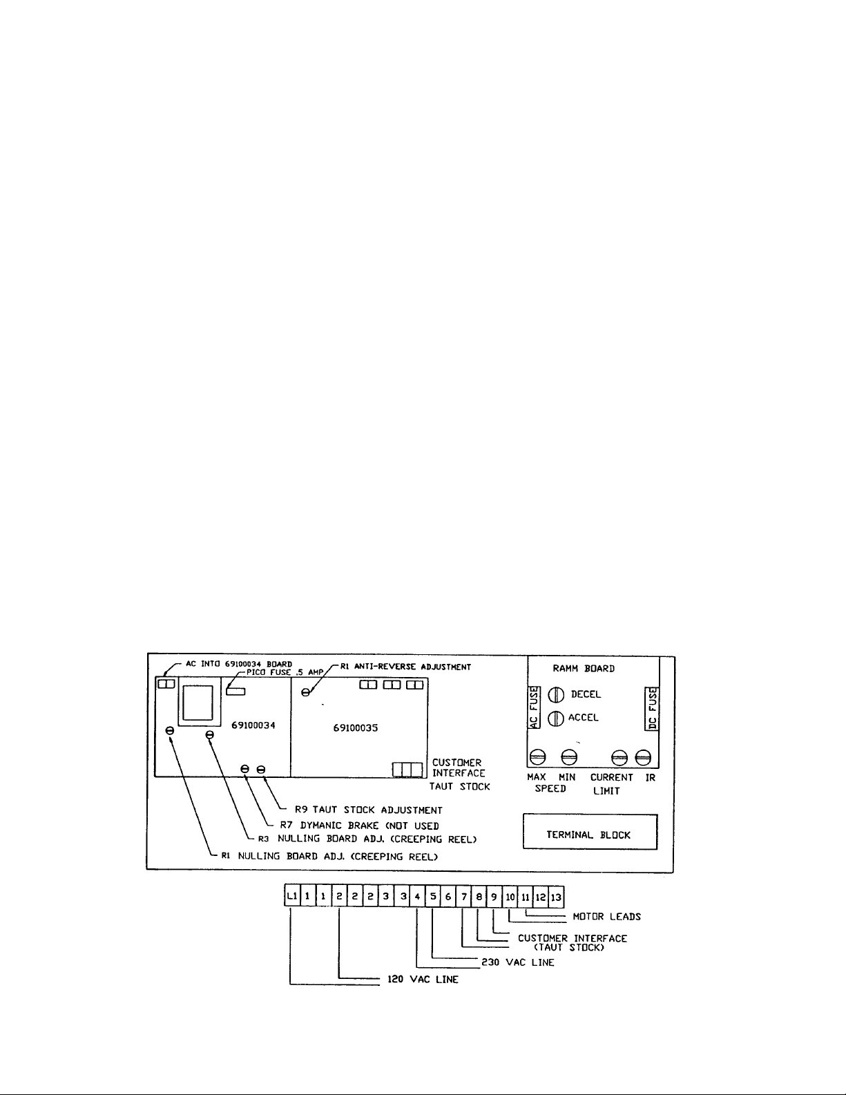
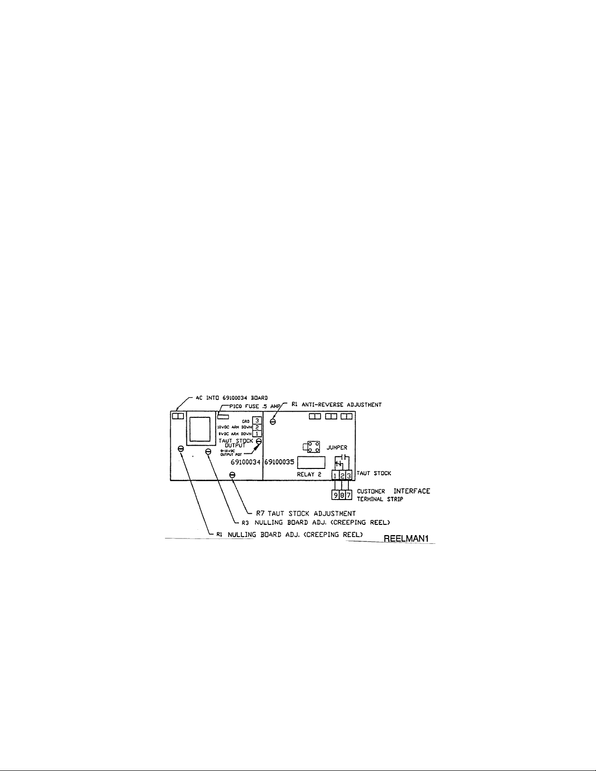
The main control unit is located behind the side access cover. Fig. Man 14 is an illustration of the layout of the control panel. This diagram lists all the components and the
approximate location of each that could be used for troubleshooting the machine if a
problem should occur. The reel can be ordered with 120 vac (1 phase) input. Terminal 4 & 5 will not be used and cannot be used unless the Ramm is changed to a 220
volt controller. If using 220 vac 1 phase input wire as indicated by drawing fig. Man 14.
This unit cannot be used with 120 vac 1 phase input unless the Ramm board is
changed to a 120 volt controller.

MECHANICAL OPERATING PROCEDURE
To Load or Unload a Coil Ring
a) If your reel has fixed center shaft go to step 1.
b) If your reel has an adjustable center shaft go to step 2.
Step 1
Release and remove the outer coil retainer from the shaft. Load or unload the coil ring.
Replace and secure the outer coil retainer. The reel is now ready for production.
Step 2
Release and remove the outer coil retainer from the shaft. If unloading, adjust the centering arms to a position so that they will release the coil. Remove the coil ring. If
loading, place the coil ring on the adjustable centering arms, adjust the centering arms
until they are tight on the coil. Replace and secure the outer coil retainer. The reel is
now ready for production.
The dancer arm was designed to operate from either side of the reel. The main reason
for this was so the reel controls could be lined up on the same side as the punch controls.
To switch the dancer arm to operate on the opposite side that it is currently located on,
first remove the counter weight if equipped with one, then turn the locking knob to disengage the lock on the dancer arm hub. Remove the dancer arm and relocate it to the
other side. Turn the hub 60 degrees and insert the dancer arm into the slot. Set to desired position. Turn the locking knob until tight on the dancer arm. Then replace
counter weight, if so equipped. The dancer arm is now ready for production running.
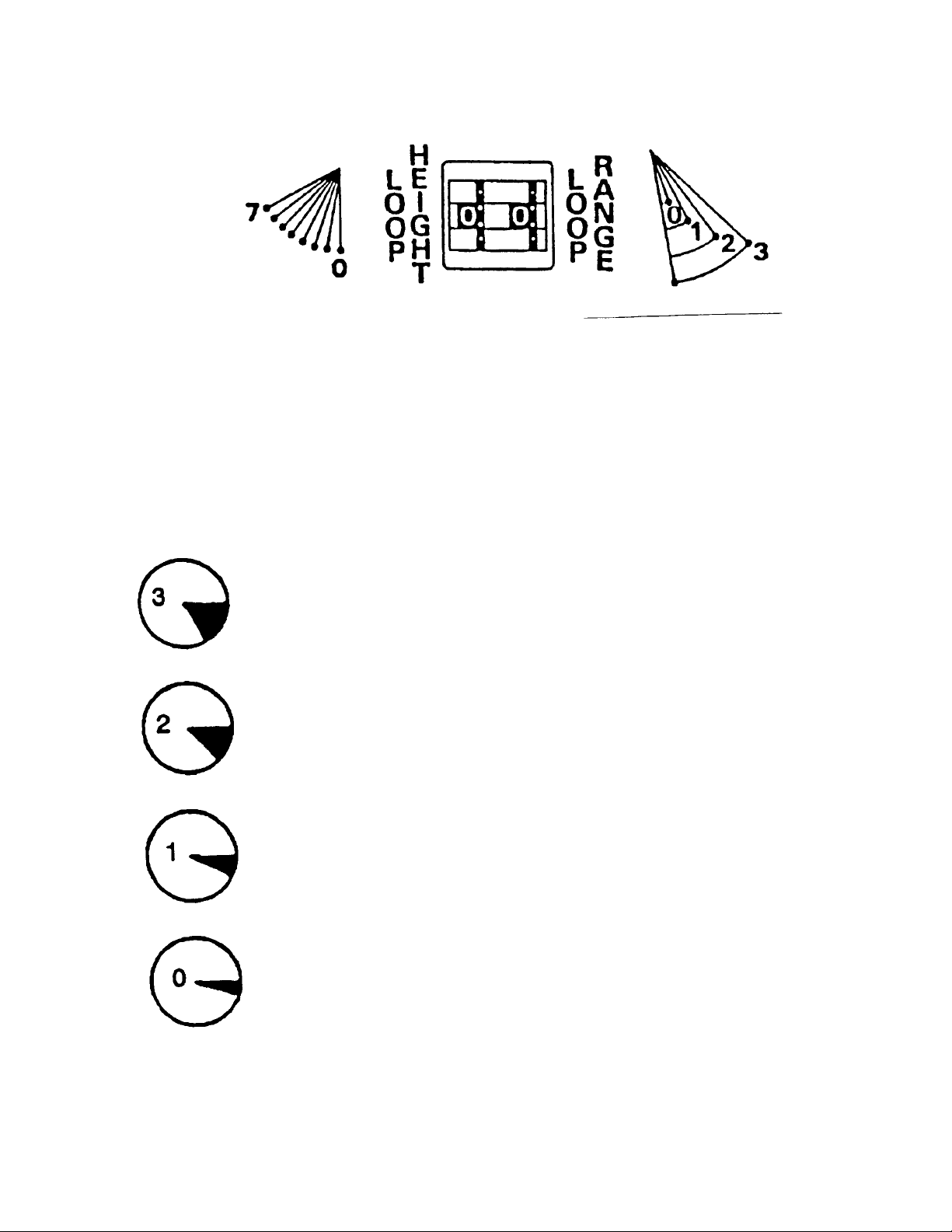
DANCER ARM LOOP HEIGHT ADJUSTMENT
Eight different loop sensing arm operating positions are selected manually during setup. By incrementing the thumbwheel height switch, the zero point of the dancer arm is
raised from it’s rest position to the angle shown (as indicated 0-7). The dancer arm will
move from rest position to the angle selected before the pallet reel begins to rotate.
DANCER ARM LOOP RANGE FUNCTION
30 degree - Loop sensing arm travels through a full 30 degree arc
to vary turntable rotation speed from slow to full speed as controlled by % speed pot.
20 degree - Loop sensing arm travels through a 20 degree arc to
vary turntable speed from slow to full speed as controlled by %
speed pot.
10 degree - Loop sensing arm travels through a 10 degree arc to
vary turntable rotation speed from slow to full speed as controlled
by % speed pot.
5 degree - Only the first 5 degrees of loop sensing arm travel is required to control turntable rotation from slow through full speed as
controlled by % speed pot.

START UP PROCEDURE
Prior to applying power to the machine the operator should review all the controls on
the machine. A brief summary of the controls is listed below.
MAIN CONSOLE & CONTROLLER
The main control console & controls are mounted on the end of the raised extended
arm of the machine. It was installed to keep the operator clear of moving parts such as
the reels. Located on the face of the console are four switches and one potentiometer
which are explained below.
1. Directional Control - The direction control switch selects the direction the reels will
turn, clockwise or counterclockwise. This is based on the operator facing the reel
on the drive side of the machine.
2. % Speed Pot - The % speed pot adjust the maximum speed that the reels will rotate and should be set up to the production rate of the machine that it is coupled
with for payout of rewind.
3. “E” Control or Dancer Arm - This selector selects between using the dancer arm
or the external loop control. If the dancer arm is selected then another console located on unit A and B has to be set up, as explained later. If the “E” control was selected, then the external unit has to be plugged into the amp connector provided
and prewired to the controller.
4. On/Off Switch - This switch is the main power switch for the controller. It must be
“ON” for the machine to function.
5. Master Start/Stop Push Button - Once the main power has turned “ON” the operator will have to pull the red lighted mushroom push-button to activate the controls.
If the mushroom push-button is not lit at this time then the operator should check that
the head position limit switch is activated. The reel cannot start unless the head is in
position.
If the mushroom push-button is lit, the operator should keep his hand clear of the reel
as the motor that drives the reel is activated. The reel will now rotate by lifting the
dancer arm.
TAUT STOCK
The Taut Stock feature monitors the loop between the reel and the external equipment.
If the loop gets small enough to possibly cause damage to the reel, the interface contacts change state and stop the external equipment.
If it is desired to monitor the reel then the following write up will explain how to connect
and adjust this feature.
The Taut Stock feature is built into the Rapid-Air board 69100035 and wires to external
terminals 7-8-9. The terminal #9 is common and from terminal 8 to 9 is normally
closed contact with power on the unit. Terminal 7 to 9 is a normally open contact with
power on the unit. These contacts are from “relay 2” chip. See diagram. This relay
has to be in place for taut stock to work. There is also a 4 prong post labeled “jump”
that has to be connected so that relay 2 can be activated. To correctly apply the
jumper, locate the post and then locate the plastic 2 prong jumper, insert the jumper so
that the left 2 vertical posts are covered. Once this is in place the taut stock feature
can be tuned.
To tune the taut stock, check that there are no connections on the terminals 7 - 8 &9,
except those that were factory connected. Attach an OHM meter to terminal 9 & 7 with
the meter set to Ohms.
Start the reel and raise the dancer arm so that the reel is running at maximum speed.
Lower the dancer arm up to a point that the stock would be taut. Hold the dancer at
this position and adjust the pot R7 of board 69100034 until the contact changes state.
Release the dancer arm. The contact should return to normal state. Raise and lower
the dancer arm 2 to 3 times to insure that the contact functions properly. Disconnect
the OHM meter and connect the customer interface.
CAUTION: The contact rating of the relay is 10VA@ 0.5 amps max. Refer to next
page for 69100034 taut stock output.
 Loading...