

Ransburg 75785, 75786, 75979, 75982, REA-90 Service Manual
...
SERVICE MANUAL
AH-94-04.7AH-94-04.7
AH-94-04.7
AH-94-04.7AH-94-04.7
(Replaces AH-94-04.6)
May - 2008
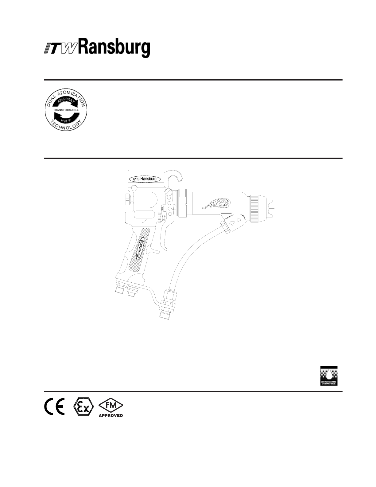
REA-90 and REA-90LREA-90 and REA-90L
REA-90 and REA-90L
REA-90 and REA-90LREA-90 and REA-90L
ELECTROSTELECTROST
ELECTROST
ELECTROSTELECTROST
APPLICAAPPLICA
APPLICA
APPLICAAPPLICA
Dual Atomization TDual Atomization T
Dual Atomization T
Dual Atomization TDual Atomization T
AA
TIC SPRATIC SPRA
A
TIC SPRA
AA
TIC SPRATIC SPRA
TT
ORSORS
T
ORS
TT
ORSORS
YY
Y
YY
echnologyechnology
echnology
echnologyechnology
MODELS:MODELS:
MODELS:
MODELS:MODELS:
75785 - ST75785 - ST
75785 - ST
75785 - ST75785 - ST
75786 - ST75786 - ST
75786 - ST
75786 - ST75786 - ST
75979 - A75979 - A
75979 - A
75979 - A75979 - A
75982 - A75982 - A
75982 - A
75982 - A75982 - A
ANDARD (SOLANDARD (SOL
ANDARD (SOL
ANDARD (SOLANDARD (SOL
ANDARD (WANDARD (W
ANDARD (W
ANDARD (WANDARD (W
VIAVIA
TT
VIA
T
VIAVIA
TT
VIAVIA
TT
VIA
T
VIAVIA
TT
VENTVENT
VENT
VENTVENT
AA
TERBORNE)TERBORNE)
A
TERBORNE)
AA
TERBORNE)TERBORNE)
OR/MGS (SOLOR/MGS (SOL
OR/MGS (SOL
OR/MGS (SOLOR/MGS (SOL
OR (WOR (W
OR (W
OR (WOR (W
AA
TERBORNE)TERBORNE)
A
TERBORNE)
AA
TERBORNE)TERBORNE)
IMPORIMPOR
IMPOR
IMPORIMPOR
carefully read SAFETY PRECAUTIONS,carefully read SAFETY PRECAUTIONS,
carefully read SAFETY PRECAUTIONS,
carefully read SAFETY PRECAUTIONS,carefully read SAFETY PRECAUTIONS,
starting on page 1, and all instructions instarting on page 1, and all instructions in
starting on page 1, and all instructions in
starting on page 1, and all instructions instarting on page 1, and all instructions in
this manual. Keep this Service Manual forthis manual. Keep this Service Manual for
this manual. Keep this Service Manual for
this manual. Keep this Service Manual forthis manual. Keep this Service Manual for
future reference.future reference.
future reference.
future reference.future reference.
BASE) BASE)
BASE)
BASE) BASE)
VENTVENT
VENT
VENTVENT
TT
ANTANT
T
ANT
TT
ANTANT
BASE) BASE)
BASE)
BASE) BASE)
: Before using this equipment,: Before using this equipment,
: Before using this equipment,
: Before using this equipment,: Before using this equipment,
Service Manual Price:Service Manual Price:
Service Manual Price: €
Service Manual Price:Service Manual Price:
25.00 (Euro)25.00 (Euro)
25.00 (Euro)
25.00 (Euro)25.00 (Euro)
$30.00 (U.S.)$30.00 (U.S.)
$30.00 (U.S.)
$30.00 (U.S.)$30.00 (U.S.)

NOTE:NOTE:
NOTE: This manual has been changed from revision
NOTE:NOTE:
Reasons for this change are noted under “Manual Change Summary” inside the back
cover of this manual.
AH-94-04.6AH-94-04.6
AH-94-04.6 to revision
AH-94-04.6AH-94-04.6
AH-94-04.7 AH-94-04.7
AH-94-04.7.
AH-94-04.7 AH-94-04.7
AH-94-04.7

CONTENTSCONTENTS
CONTENTS
CONTENTSCONTENTS
SAFETY:SAFETY:
SAFETY:
SAFETY:SAFETY:
REA-90 and 90L Spray Applicators - Contents
PAGEPAGE
PAGE
PAGEPAGE
1-71-7
1-7
1-71-7
SAFETY PRECAUTIONS............................................................................................................
HAZARDS / SAFEGUARDS........................................................................................................
ATEX:ATEX:
ATEX:
ATEX:ATEX:
EUROPEAN ATEX DIRECTIVE..................................................................................................
EUROPEAN ATEX LABELS........................................................................................................
INTRODUCTION:INTRODUCTION:
INTRODUCTION:
INTRODUCTION:INTRODUCTION:
GENERAL DESCRIPTION..........................................................................................................
REA-90 WITH AVIATOR..............................................................................................................
75785 SOLVENT BASE REA-90 STANDARD AND
75979 SOLVENT BASE REA-90 AVIATOR / MGS....................................................................
75786 WATERBORNE REA-90 STANDARD AND
75982 WATERBORNE REA-90 AVIATOR.................................................................................
INSTALLATION:INSTALLATION:
INSTALLATION:
INSTALLATION:INSTALLATION:
75785 STANDARD SOLVENT BASE AND 75979 AVIATOR /
MGS SOLVENT BASE INSTALLATION.....................................................................................
FILTERS.......................................................................................................................................
75786 STANDARD WATERBORNE AND 75982 AVIATOR
WATERBORNE INSTALLATION................................................................................................
ISOLATION SYSTEM INSTALLATION GUIDELINES...............................................................
WATERBORNE HOSE FITTING INSTALLATION.....................................................................
FLUID HOSE FITTING INSTALLATION.....................................................................................
AIR HOSE FITTING INSTALLATION.........................................................................................
PAINT PREPARATION...............................................................................................................
SPRAY TECHNOLOGY CONVERSION PROCEDURE..........................................................
SPRAY PATTERN ADJUSTMENT.............................................................................................
APPLICATOR TO TARGET DISTANCE....................................................................................
AIR CAP / FLUID NOZZLE SELECTION CHART.....................................................................
AIR CAP / FLUID NOZZLE PERFORMANCE CHART.............................................................
1
2-7
8-108-10
8-10
8-108-10
8-9
9-10
11-1611-16
11-16
11-1611-16
11-12
12
13-14
15-16
17-2617-26
17-26
17-2617-26
17-18
18
19
20-21
21
22
22
22
23
24
24
25
26
MAINTENANCE:MAINTENANCE:
MAINTENANCE:
MAINTENANCE:MAINTENANCE:
SUITABLE SOLVENTS FOR CLEANING REA-90 APPLICATORS.........................................
ROUTINE SCHEDULE................................................................................................................
APPLICATOR ASSEMBLY CLEANING PROCEDURE............................................................
FLUSHING PROCEDURES........................................................................................................
APPLICATOR REPAIR................................................................................................................
EQUIPMENT REQUIRED...........................................................................................................
TO REMOVE THE APPLICATOR FROM THE WORK SITE....................................................
FLUID NOZZLE............................................................................................................................
NEEDLE / ELECTRODE..............................................................................................................
NEEDLE / ELECTRODE RESISTANCE TESTING...................................................................
(Continued On Next Page)(Continued On Next Page)
(Continued On Next Page)
(Continued On Next Page)(Continued On Next Page)
AH-94-04.7
27-5827-58
27-58
27-5827-58
27
28-29
29-30
30-31
31
31
31-33
34-35
35
36

REA-90 and 90L Spray Applicators - Contents
CONTENTS (Cont.)CONTENTS (Cont.)
CONTENTS (Cont.)
CONTENTS (Cont.)CONTENTS (Cont.)
MAINTENANCE: (continued)MAINTENANCE: (continued)
MAINTENANCE: (continued)
MAINTENANCE: (continued)MAINTENANCE: (continued)
PAGEPAGE
PAGE
PAGEPAGE
27-5827-58
27-58
27-5827-58
BARREL ASSEMBLY...................................................................................................................
HOOK / TRANSFORMER ASSEMBLY......................................................................................
HOOK / TRANSFORMER ON/OFF SWITCH REPLACEMENT...............................................
HANDLE.......................................................................................................................................
FAN AIR VALVE...........................................................................................................................
AIR VALVE...................................................................................................................................
TRIGGER.....................................................................................................................................
NEEDLE SHAFT RETURN SPRING REPLACEMENT.............................................................
LOW VOLTAGE CABLE PLUG ASSEMBLY REPLACEMENT................................................
REPLACEMENT...........................................................................................................................
LOW VOLTAGE CABLE REPLACEMENT.................................................................................
FLUID TUBE (SOLVENT BASE APPLICATORS)......................................................................
FLUID HOSE (SOLVENT BASE APPLICATORS).....................................................................
FLUID HOSE (WATERBORNE APPLICATORS)......................................................................
AIR LINE.......................................................................................................................................
FLUID TUBE BRACKET..............................................................................................................
TRIGGER ADJUSTMENT...........................................................................................................
FAN AIR ADJUSTMENT..............................................................................................................
FLUID DELIVERY ADJUSTMENT..............................................................................................
ATOMIZING AIR ADJUSTMENT................................................................................................
TROUBLESHOOTING GUIDE....................................................................................................
36-41
41-43
43
44
44-45
46-47
47
47
48
48-49
49-50
50-51
51-52
52-53
53-54
54
54-55
55
55
55
56-58
PARTS IDENTIFICATION:PARTS IDENTIFICATION:
PARTS IDENTIFICATION:
PARTS IDENTIFICATION:PARTS IDENTIFICATION:
75785 SOLVENT BASE (STANDARD) AND
75979 SOLVENT BASE (AVIATOR / MGS) /
MODEL IDENTIFICATION / PARTS LIST...................................................................................
75786 WATERBORNE (STANDARD) AND 75982
WATERBORNE (AVIATOR) / MODEL IDENTIFICATION /
PARTS LIST..................................................................................................................................
RECOMMENDED SPARE PARTS.............................................................................................
MISC. PARTS...............................................................................................................................
SERVICE KITS.............................................................................................................................
WARRANTY POLICIES:WARRANTY POLICIES:
WARRANTY POLICIES:
WARRANTY POLICIES:WARRANTY POLICIES:
LIMITED WARRANTY..................................................................................................................
59-7059-70
59-70
59-7059-70
59-64
65-69
69
70
70
7171
71
7171
71
AH-94-04.7

REA-90 and 90L Spray Applicators - Contents
AH-94-04.7

REA-90 and 90L Spray Applicators - Safety
SAFETYSAFETY
SAFETY
SAFETYSAFETY
SAFETY PRECAUTIONSSAFETY PRECAUTIONS
SAFETY PRECAUTIONS
SAFETY PRECAUTIONSSAFETY PRECAUTIONS
W A R N I N GW A R N I N G
W A R N I N G
W A R N I N GW A R N I N G
!!
!
!!
Before operating, maintaining or servicing any
ITW Ransburg electrostatic coating system, read
and understand all of the technical and safety
literature for your ITW Ransburg products. This
manual contains information that is important for
you to know and understand. This information
relates to USER SAFETY and PREVENTING
EQUIPMENT PROBLEMS. To help you recognize
this information, we use the following symbols.
Please pay particular attention to these sections.
A WARNING! states information to alert youA WARNING! states information to alert you
A WARNING! states information to alert you
A WARNING! states information to alert youA WARNING! states information to alert you
to a situation that might cause serious injuryto a situation that might cause serious injury
to a situation that might cause serious injury
to a situation that might cause serious injuryto a situation that might cause serious injury
if instructions are not followed.if instructions are not followed.
if instructions are not followed.
if instructions are not followed.if instructions are not followed.
A CAUTION! states information that tellsA CAUTION! states information that tells
A CAUTION! states information that tells
A CAUTION! states information that tellsA CAUTION! states information that tells
how to prevent damage to equipment or howhow to prevent damage to equipment or how
how to prevent damage to equipment or how
how to prevent damage to equipment or howhow to prevent damage to equipment or how
to avoid a situation that might cause minorto avoid a situation that might cause minor
to avoid a situation that might cause minor
to avoid a situation that might cause minorto avoid a situation that might cause minor
injury.injury.
injury.
injury.injury.
A NOTE is information relevant to theA NOTE is information relevant to the
A NOTE is information relevant to the
A NOTE is information relevant to theA NOTE is information relevant to the
procedure in progress.procedure in progress.
procedure in progress.
procedure in progress.procedure in progress.
> The user
with the Safety Section in this manual and
the ITW Ransburg safety literature therein
identified.
> This manual
oughly understood by
operate, clean or maintain this equipment!
Special care should be taken to ensure that
WARNINGSWARNINGS
the
WARNINGS and safety requirements
WARNINGSWARNINGS
for operating and servicing the equipment
are followed. The user should be aware of
and adhere to
codes and ordinances as well as
33 SAFETY STANDARD33 SAFETY STANDARD
33 SAFETY STANDARD, prior to
33 SAFETY STANDARD33 SAFETY STANDARD
installing, operating, and/or servicing this
equipment.
MUSTMUST
MUST read and be familiar
MUSTMUST
MUSTMUST
MUST be read and thor-
MUSTMUST
ALLALL
ALL personnel who
ALLALL
ALL ALL
ALL local building and fire
ALL ALL
W A R N I N GW A R N I N G
W A R N I N G
W A R N I N GW A R N I N G
!!
!
!!
NFPA-NFPA-
NFPA-
NFPA-NFPA-
While this manual lists standard specifications
and service procedures, some minor deviations
may be found between this literature and your
equipment. Differences in local codes and plant
requirements, material delivery requirements, etc.,
make such variations inevitable. Compare this
manual with your system installation drawings
and appropriate ITW Ransburg equipment
manuals to reconcile such differences.
Careful study and continued use of this manual will
provide a better understanding of the equipment
and process, resulting in more efficient operation,
longer trouble-free service and faster, easier
troubleshooting. If you do not have the manuals
and safety literature for your Ransburg system,
contact your local ITW Ransburg representative
or ITW Ransburg.
> The hazards shown on the following
page may occur during the normal use of
this equipment. Please read the hazard
chart beginning on page 2.
11
1
11
AH-94-04.7
REA-90 and 90L Spray Applicators - Safety
AREAAREA
AREA
AREAAREA
Tells where hazards
may occur.
Spray AreaSpray Area
Spray Area
Spray AreaSpray Area
HAZARDHAZARD
HAZARD
HAZARDHAZARD
Tells what the hazard is.
Fire Hazard
Improper or inadequate opera-tion
and maintenance procedures will
cause a fire hazard.
Protection against inadvertent
arcing that is capable of causing
fire or explosion is lost if any safety
interlocks are disabled during
operation. Frequent power supply
shutdown indicates a problem in
the system requiring correction.
SAFEGUARDSSAFEGUARDS
SAFEGUARDS
SAFEGUARDSSAFEGUARDS
Tells how to avoid the hazard.
Fire extinguishing equipment must be present in the
spray area and tested periodically.
Spray areas must be kept clean to prevent the
accumulation of combustible residues.
Smoking must never be allowed in the spray area.
The high voltage supplied to the atomizer must be
turned off prior to cleaning, flushing or maintenance.
When using solvents for cleaning:
Those used for equipment flushing should have flash
points equal to or higher than those of the coating
material.
Those used for general cleaning must have flash
points above 100oF (37.8oC).
Spray booth ventilation must be kept at the rates
required by NFPA-33, OSHA, and local codes. In
addition, ventilation must be maintained during
cleaning operations using flammable or combustible
solvents.
Electrostatic arcing must be prevented.
Test only in areas free of combustible material.
Testing may require high voltage to be on, but only as
instructed.
Non-factory replacement parts or unauthorized
equipment modifications may cause fire or injury.
If used, the key switch bypass is intended for use only
during setup operations. Production should never be
done with safety interlocks disabled.
Never use equipment intended for use in waterborne
installations to spray solvent based materials.
The paint process and equipment should be set up
and operated in accordance with NFPA-33, NEC, and
OSHA requirements.
AH-94-04.7
22
2
22

REA-90 and 90L Spray Applicators - Safety
AREAAREA
AREA
AREAAREA
Tells where hazards
may occur.
Toxic SubstancesToxic Substances
Toxic Substances
Toxic SubstancesToxic Substances
ExplosionExplosion
Explosion
ExplosionExplosion
Hazard /Hazard /
Hazard /
Hazard /Hazard /
IncompatibleIncompatible
Incompatible
IncompatibleIncompatible
MaterialsMaterials
Materials
MaterialsMaterials
HAZARDHAZARD
HAZARD
HAZARDHAZARD
Tells what the hazard is.
Certain material may be harmful if
inhaled, or if there is contact with
the skin.
Halogenated hydrocarbon solvents,
for example: methylene chloride
and 1,1,1, - Trichloroethane, are
not chemically compatible with the
aluminum that might be used in
many system components. The
chemical reaction caused by these
solvents reacting with aluminum
can become violent and lead to an
equipment explosion.
SAFEGUARDSSAFEGUARDS
SAFEGUARDS
SAFEGUARDSSAFEGUARDS
Tells how to avoid the hazard.
Follow the requirements of the Material Safety Data
Sheet supplied by coating material manufacturer.
Adequate exhaust must be provided to keep the air
free of accumulations of toxic materials.
Use a mask or respirator whenever there is a chance
of inhaling sprayed materials. The mask must be
compatible with the material being sprayed and its
concentration. Equipment must be as prescribed by
an industrial hygienist or safety expert, and be NIOSH
approved.
The REA-90 and REA-90L require that aluminum inlet
fittings be replaced with stainless steel. (See
accessories list.) Aluminum is widely used in other
spray application equipment - such as material pumps,
regulators, valves, etc. Check all other equipment
items before use and make sure they can also be
used safely with these solvents. Read the label or
data sheet for the material you intend to spray. If in
doubt as to whether or not a coating or cleaning
material is compatible, contact your material supplier.
Any other type of solvent may be used with aluminum
equipment.
Intended UseIntended Use
Intended Use
Intended UseIntended Use
(Waterborne Only)
Using coating materials and/or
cleaning and flushing solvents
which have flash points below
100F (37.8°C) may cause a fire
hazard.
This system is intended for use with waterborne
coating formulations only.
Waterborne, waterbase and water reducible coatings
are considered the same. Although they may not be
highly flammable, their residues are considered
combustible.
33
3
33
AH-94-04.7
REA-90 and 90L Spray Applicators - Safety
AREAAREA
AREA
AREAAREA
Tells where hazards
may occur.
ElectricalElectrical
Electrical
ElectricalElectrical
EquipmentEquipment
Equipment
EquipmentEquipment
HAZARDHAZARD
HAZARD
HAZARDHAZARD
Tells what the hazard is.
High voltage equipment is utilized.
Arcing in areas of flammable or
combustible materials may occur.
Personnel are exposed to high
voltage during operation and
maintenance.
Protection against inadvertent
arcing that may cause a fire or
explosion is lost if safety circuits
are disabled during operation.
Frequent power supply shutdown
indicates a problem in the system
which requires correction.
An electrical arc can ignite coating
materials and cause a fire or
explosion.
SAFEGUARDSSAFEGUARDS
SAFEGUARDS
SAFEGUARDSSAFEGUARDS
Tells how to avoid the hazard.
The power supply, optional remote control cabinet,
and all other electrical equipment must be located
outside Class I or II, Division 1 and 2 hazardous
areas. (Exception: AVIATOR series applicators)
(Refer to NFPA-33.)
Turn the power supply OFF before working on the
equipment.
Test only in areas free of flammable or combustible material.
Testing may require high voltage to be on, but only
as instructed.
Production should never be done with the safety
circuits disabled.
Before turning the high voltage on, make sure no
objects are within the sparking distance.
AH-94-04.7
44
4
44

REA-90 and 90L Spray Applicators - Safety
AREAAREA
AREA
AREAAREA
Tells where hazards
may occur.
Spray AreaSpray Area
Spray Area
Spray AreaSpray Area
HAZARDHAZARD
HAZARD
HAZARDHAZARD
Tells what the hazard is.
Electrostatic Arcing Never operate the spray applicator without properly
SAFEGUARDSSAFEGUARDS
SAFEGUARDS
SAFEGUARDSSAFEGUARDS
Tells how to avoid the hazard.
grounding the following.
A. Operators
Operators must be grounded. Rubber soled
insulating shoes should not be worn. Grounding
leg straps may be used.
Operators must maintain contact with the
handle of the applicator. If work gloves are used,
the palm section should be cut out.
Operators must remove from themselves all
metal objects that are not grounded.
NOTE:NOTE:
NOTE: REFER TO NFPA-33 REGARDING
NOTE:NOTE:
OPERATOR GROUNDING.
B. Parts being sprayed. Resistance between the
part and a grounded conveyor must not exceed
1 megohm.
C. Every metal and conductive object in the spray
area. This includes the booth, parts hangers,
fire extinguishers, conductive flooring, etc.
Grounded conductive flooring must be provided in the
spray area.
Turn off voltage at the power supply before flushing
out, cleaning, or removing any parts from the
applicator.
Provide proper protection for waterborne supply
systems.
Never install a spray applicator into a fluid system
using an isolated solvent supply.
Always discharge Waterborne system capacitance
prior to servicing.
Do not touch applicator electrode while applicator is
energized.
55
5
55
AH-94-04.7

REA-90 and 90L Spray Applicators - Safety
AREAAREA
AREA
AREAAREA
Tells where hazards
may occur.
General Use andGeneral Use and
General Use and
General Use andGeneral Use and
MaintenanceMaintenance
Maintenance
MaintenanceMaintenance
HAZARDHAZARD
HAZARD
HAZARDHAZARD
Tells what the hazard is.
Improper operation or maintenance
may create a hazard.
Personnel must be properly trained
in the use of this equipment.
SAFEGUARDSSAFEGUARDS
SAFEGUARDS
SAFEGUARDSSAFEGUARDS
Tells how to avoid the hazard.
Personnel must be given training in accordance with
the requirements of NFPA-33.
Instructions and safety precautions must be read and
understood prior to using this equipment.
Comply with appropriate local, state, and national
codes governing ventilation, fire protection, operation
maintenance, and housekeeping. Reference OSHA,
NFPA-33, and your insurance company requirements.
Always turn power to the power supply OFF, unplug
the electrical cord from its outlet, and remove the
front panel fuse, before opening the power supply
door. If necessary, lock the power supply out so that
it cannot be turned ON until the work is finished.
Whenever removing high voltage cables from
equipment, ground the contact end of the cable by
holding the cable such that the contact touches earth
ground for several seconds. Do not touch the contact
until it has been grounded. This will reduce the
possibility of residual charge causing electrical shock.
The High Voltage Multiplier Assembly contains energy
storage components that can cause serious shock
injury, and therefore is not field repairable. Warranty
will be voided if the High Voltage Multiplier seal is
broken. If the High Voltage Multiplier is defective
contact your authorized ITW Ransburg representative
for exchange or repair.
The High Voltage Multiplier and high voltage cable
contain significant capacitance that will store charge.
Allow approximately 10 seconds for this charge to
bleed off before opening the cabinet door or removing
the high voltage cable from the power supply or spray
applicator.
AH-94-04.7
66
6
66

REA-90 and 90L Spray Applicators - Safety
AREAAREA
AREA
AREAAREA
Tells where hazards
may occur.
General Use andGeneral Use and
General Use and
General Use andGeneral Use and
MaintenanceMaintenance
Maintenance
MaintenanceMaintenance
HAZARDHAZARD
HAZARD
HAZARDHAZARD
Tells what the hazard is.
Use of hand tools may cause
cumulative trauma disorders
(CTD's). CTD's or musculoskeletal
disorders, involve damage to the
hands, wrists, elbows, shoulders,
neck and back. Carpal tunnel
syndrome and tendinitis (such as
tennis elbow or rotator cuff
syndrome) are examples of CTD's.
CTD's when using hand tools, tend
to affect the upper extremities.
Factors which may increase the
risk of developing a CTD include:
1. High frequency of the activity.
2. Excessive force, such as
gripping, pinching or pressing
with the hands and fingers.
SAFEGUARDSSAFEGUARDS
SAFEGUARDS
SAFEGUARDSSAFEGUARDS
Tells how to avoid the hazard.
Risk is reduced by avoiding or lessening the listed
hazards.
CTD's can also be caused by such activities as
sewing, golf, tennis and bowling, to name a few.
Pain, tingling, or numbness in the shoulder, forearm,
wrists, hands, or fingers, especially during the night,
may be early symptoms of a CTD. Do not ignore
them. Should you experience any such symptoms,
see a physician immediately. Other early symptoms
may include vague discomfort in the hand, loss of
manual dexterity, and nonspecific pain in the arm.
Ignoring early symptoms and continued repetitive
use of the arm, wrist and hand can lead to serious
disability.
3. Extreme or awkward finger,
wrist or arm positions.
4. Excessive duration of the
activity.
5. Tool vibration.
6. Repeated pressure on a
body part.
7. Working in cold temperatures.
77
7
77
AH-94-04.7

REA-90 and 90L Spray Applictors - Atex
EUROPEAN AEUROPEAN A
EUROPEAN A
EUROPEAN AEUROPEAN A
The following instructions apply to equipment
covered by certificate number Sira 08ATEX5040X:
1. The equipment may be used with flammable
gases and vapors with apparatus groups II and
with temperature class T6.
2. The equipment is only certified for use in ambient
temperatures in the range +12.8°C to +40°C and
should not be used outside this range.
3. Installation shall be carried out by suitably
trained personnel in accordance with the applicable
code of practice e.g. EN 60079-14: 1997.
4. Inspection and maintenance of this equipment
shall be carried out by suitably trained personnel
in accordance with the applicable code of practice
e.g. EN 60079-17.
5. Repair of this equipment shall be carried out by
suitable trained personnel in accordance with the
applicable code of practice e.g. EN 60079-19.
6. Putting into service, use, assembling, and
adjustment of the equipment shall be fitted by
suitably trained personnel in accordance with the
manufacturer's documentation.
Refer to the "Table of Contents" of this service
manual:
a. Installation
b. Operation
c. Maintenance
d. Parts Identification
TEX DIRECTIVE 94/9/EC, ANNEX II, 1.0.6TEX DIRECTIVE 94/9/EC, ANNEX II, 1.0.6
TEX DIRECTIVE 94/9/EC, ANNEX II, 1.0.6
TEX DIRECTIVE 94/9/EC, ANNEX II, 1.0.6TEX DIRECTIVE 94/9/EC, ANNEX II, 1.0.6
8. The certification of this equipment relies upon
the following materials used in its construction:
If the equipment is likely to come into contact with
aggressive substances, then it is the responsibility
of the user to take suitable precautions that prevent
it from being adversely affected, thus ensuring
that the type of protection provided by the equipment
is not compromised.
Aggressive substances: e.g. acidic liquids or
gases that may attack metals, or solvents that
may affect polymeric materials.
Suitable precautions: e.g. regular checks as part
of routine inspections or establishing from the
material's data sheets that it is resistant to specific
chemicals.
Refer to "Specifications" in the "Introduction"
section:
a. All fluid passages contain stainless steel
or nylon fittings.
b. High voltage cascade is encapsulated
with a solvent resistant epoxy.
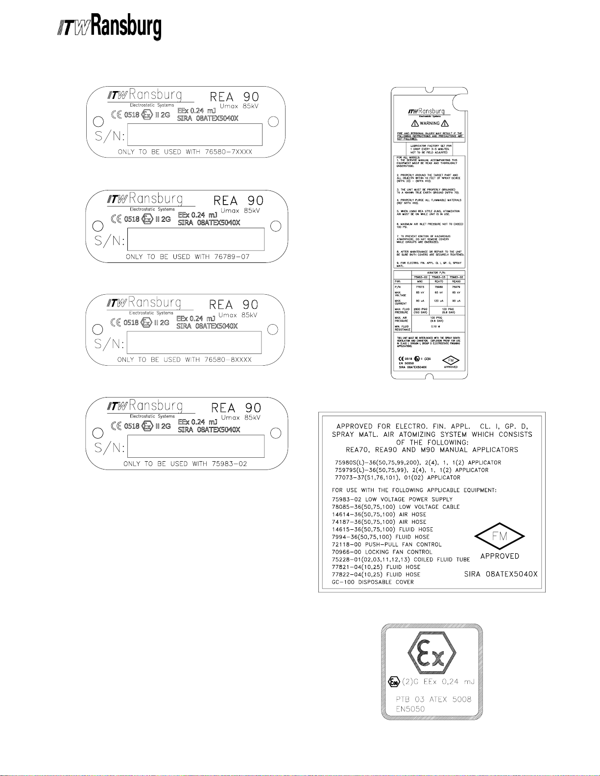
9. A recapitulation of the certification marking is
detailed in the "Atex" section, on the next page,
drawing numbers: 72562, 76180, 76801, 76856,
76860, 77319, 77319-01, 77322, 77325, 77657,
79132, and 79318.
10. The characteristics of the equipment shall be
detailed e.g. electrical, pressure, and voltage
parameters.
7. Components to be incorporated into or used as
replacement parts of the equipment shall be fitted
by suitably trained personnel in accordance with
the manufacturer's documentation.
AH-94-04.7
The manufacturer should note that, on being put
into service, the equipment must be accompanied
by a translation of the instructions in the language
or languages of the country in which the equipment
is to be used and by the instructions in the original
language.
88
8
88

REA-90 and 90L Spray Applicators - Atex
REA-90 and 90L ElectrostaticREA-90 and 90L Electrostatic
REA-90 and 90L Electrostatic
REA-90 and 90L ElectrostaticREA-90 and 90L Electrostatic
Applicators 75785, 75786, 75979,Applicators 75785, 75786, 75979,
Applicators 75785, 75786, 75979,
Applicators 75785, 75786, 75979,Applicators 75785, 75786, 75979,
and 75982 Aand 75982 A
and 75982 A
and 75982 Aand 75982 A
Product MarkingProduct Marking
Product Marking
Product MarkingProduct Marking
DefinitionsDefinitions
Definitions
DefinitionsDefinitions
Ex Certificate Number: Sira 08ATEX5040X
Sira = Notified Body performing EC-type
examination
08 = Year of certification
ATEX = Reference to ATEX Directive
5 = Protection Concept Code (code 5 is titled
Encapsulation)
040 = Document serial number
X = Special conditions for safe use apply
Special conditions for safe use: The REA-90 and
90L 75785, 75786, 75979, and 75982 Electrostatic
Applicators shall only be used with associated
76580-7XXXX, 76580-6XXXX, 76789, and 75983
Control Unit.
TEXTEX
TEX
TEXTEX
Label 76180Label 76180
Label 76180
Label 76180Label 76180
Label 76801Label 76801
Label 76801
Label 76801Label 76801
Product MarkingProduct Marking
Product Marking
Product MarkingProduct Marking
II 2 GII 2 G
II 2 G
II 2 GII 2 G
Ex = Specific marking of explosive protection
II = Equipment Group hazardous area characteristics
2 = Equipment Category
G = Type of explosive atmosphere (gases, vapors,
or mists)
EEx 0.24mJEEx 0.24mJ
EEx 0.24mJ = The REA-90 and 90L Applicators
EEx 0.24mJEEx 0.24mJ
757875, 75786, 75979, and 75982 are suitable for
use in automatic spraying installations complying
with EN 50 050 as they are a Type A class with a
discharge energy limit of 0.24mJ.
Label 72562Label 72562
Label 72562
Label 72562Label 72562
Label 76856Label 76856
Label 76856
Label 76856Label 76856
Label 76860Label 76860
Label 76860
Label 76860Label 76860
99
9
99
AH-94-04.7
REA-90 and 90L Spray Applictors - Atex
Label 77319Label 77319
Label 77319
Label 77319Label 77319
Label 77319-01Label 77319-01
Label 77319-01
Label 77319-01Label 77319-01
Label 77322Label 77322
Label 77322
Label 77322Label 77322
Label 79657Label 79657
Label 79657
Label 79657Label 79657
W
Label 77325Label 77325
Label 77325
Label 77325Label 77325
Label 79132Label 79132
Label 79132
Label 79132Label 79132
Label 79318Label 79318
Label 79318
Label 79318Label 79318
AH-94-04.7
1010
10
1010

REA-90 and 90L Spray Applicators - Introduction
INTRODUCTIONINTRODUCTION
INTRODUCTION
INTRODUCTIONINTRODUCTION
GENERAL DESCRIPTIONGENERAL DESCRIPTION
GENERAL DESCRIPTION
GENERAL DESCRIPTIONGENERAL DESCRIPTION
The REA process is an air-atomized method for
electrostatically applying coatings to objects. The
REA applicator system (technology) applies a
high voltage DC charge to the applicator electrode,
creating an electrostatic field between the atomizer
and the target object.
The REA-90 or REA-90L Delta Electrostatic Spray
Applicators (see Figures 1 and 2) applies a -85kV
DC charge to the coating materials at the point of
atomization. This electrostatic charge allows a
more efficient, uniform application of coating
material to the front, edges, sides, and back of
products. It is highly suitable for applying coatings
to a variety of surface configurations: large targets,
small parts, tubular wares, concave and recessed
parts, etc. Because it is a grounded fluid system
(for solvent based systems), it is highly suitable
for applying a wide range of solvent reduced
coatings such as enamels, lacquers, epoxies,
etc. The 75786 and 75982 models are available to
accommodate waterborne materials.
The REA-90 and REA-90L electrostatic spray
applicators are transformable between air spray
and HVLP spray technology. The REA-90 is
designed for use as a conventional air spray (highpressure) or high volume/low-pressure (HVLP)
air spray to atomize the coating material. By
changing a select few parts, the applicator may be
transformed to be operated in either spray mode.
(See "Spray Technology Conversion Procedure"
in the "Installation" section for details.)
overspray around and deposit it on the back
surface of the target. Therefore, a high percentage
of the coating is deposited on the target.
One of the many features of the REA applicator
system is that the electrical energy, which is
available from the resistive charging electrode, is
limited to the optimum level of safety and efficiency.
This system is incapable of releasing sufficient
electrical or thermal energy during normal operating
conditions to cause ignition of specific hazardous
materials in their most easily ignited concentrations
in air (see NFPA-33).
The control unit provides low voltage output to the
applicator and contains controls for AC on/off,
high voltage adjust, kV and micro amp meter.
As the applicator electrode approaches ground,
the control unit and applicator circuitry cause the
high voltage and current to “fold back” and decrease
towards zero for models 75785, 75979, and 75982.
For models 75786, the fold back circuitry in the
control unit has been turned off to provide maximum
voltage for waterborne applications.
W A R N I N GW A R N I N G
W A R N I N G
W A R N I N GW A R N I N G
!!
!
!!
> Never use a standard solvent base
applicator system (75785 or 75979) on a
standard waterborne control unit. Failure
to comply may cause damage to equipment and/or risk of fire and injury.
A regulated pressure fluid system delivers coating
material to the atomizer. At the time of triggering
the applicator, fan and atomization air is introduced,
which atomizes the coating material into a spray
mist. The atomized spray particles under the
influence of the electrostatic field become
electrically charged. The charged particles are
attracted to, and deposited on, the target object.
The forces between the charged particles and the
grounded target are sufficient to turn most normal
1111
11
1111
W A R N I N GW A R N I N G
W A R N I N G
W A R N I N GW A R N I N G
!!
!
!!
> Never use a waterborne (75786 or
75982) REA-90 system to spray solvent
reduced coating materials. Failure to
comply may cause damage to equipment
and/or risk of fire and injury.
AH-94-04.7

REA-90 and 90L Spray Applicators - Introduction
W A R N I N GW A R N I N G
W A R N I N G
W A R N I N GW A R N I N G
!!
!
!!
> When more than one waterborne
applicator is fed from a common isolated
supply, there is a potential for electrical
energy discharge through any other
applicators when one applicator is triggered. Depending upon the system
capacity, this discharge could be hazardous.
TMTM
TM
REA-90 WITH AREA-90 WITH A
REA-90 WITH A
REA-90 WITH AREA-90 WITH A
The REA-90 may be used with the AVIATOR
power generator in hazardous locations. This
equipment meets Class 1, Division 1, and Group
D hazardous location requirements. This allows
moving the REA-90 power source inside most
spray booths or areas where the standard control
unit may not be conveniently located. Examples
are airplane hangars, etc.
VIAVIA
VIA
VIAVIA
TT
T
TT
OROR
OR
OROR
TMTM
NOTESNOTES
NOTES
NOTESNOTES
AH-94-04.7
1212
12
1212

REA-90 and 90L Spray Applicators - Introduction
75785 SOL75785 SOL
75785 SOL
75785 SOL75785 SOL
REA-90 STREA-90 ST
REA-90 ST
REA-90 STREA-90 ST
SPECIFICASPECIFICA
SPECIFICA
SPECIFICASPECIFICA
Environmental / PhysicalEnvironmental / Physical
Environmental / Physical
Environmental / PhysicalEnvironmental / Physical
Applicator Length:Applicator Length:
Applicator Length:
Applicator Length:Applicator Length:
Weight:Weight:
Weight: 28 ounces (793.8g)
Weight:Weight:
Hose and CableHose and Cable
Hose and Cable
Hose and CableHose and Cable
Lengths:Lengths:
Lengths:
Lengths:Lengths:
AtomizerAtomizer
Atomizer
AtomizerAtomizer
Assembly (Std):Assembly (Std):
Assembly (Std):
Assembly (Std):Assembly (Std):
ElectricalElectrical
Electrical
ElectricalElectrical
Operating Voltage:Operating Voltage:
Operating Voltage: 85kV DC (-) maximum
Operating Voltage:Operating Voltage:
Current Output:Current Output:
Current Output: 90 microamperes maximum
Current Output:Current Output:
VENTVENT
VENT
VENTVENT
ANDARDANDARD
ANDARD
ANDARDANDARD
TIONSTIONS
TIONS
TIONSTIONS
11-inches (279.4mm)
36 ft (Optional: 50, 75,
and 100 ft)
4907-45, 4904-65R
Air Spray
75601-00, 75600-01 HVLP
(foldback)
BASE BASE
BASE
BASE BASE
75979 SOL75979 SOL
75979 SOL
75979 SOL75979 SOL
REA-90 AREA-90 A
REA-90 A
REA-90 AREA-90 A
SPECIFICASPECIFICA
SPECIFICA
SPECIFICASPECIFICA
Environmental / PhysicalEnvironmental / Physical
Environmental / Physical
Environmental / PhysicalEnvironmental / Physical
Applicator Length:Applicator Length:
Applicator Length:
Applicator Length:Applicator Length:
Weight:Weight:
Weight: 28 ounces (793.8g)
Weight:Weight:
Hose and CableHose and Cable
Hose and Cable
Hose and CableHose and Cable
Lengths:Lengths:
Lengths:
Lengths:Lengths:
AtomizerAtomizer
Atomizer
AtomizerAtomizer
Assembly (Std):Assembly (Std):
Assembly (Std):
Assembly (Std):Assembly (Std):
ElectricalElectrical
Electrical
ElectricalElectrical
Operating Voltage:Operating Voltage:
Operating Voltage: 85kV DC (-) maximum
Operating Voltage:Operating Voltage:
Current Output:Current Output:
Current Output: 90 microamperes maximum
Current Output:Current Output:
VENTVENT
VENT
VENTVENT
VIAVIA
TT
VIA
T
VIAVIA
TT
TIONSTIONS
TIONS
TIONSTIONS
11-inches (279.4mm)
36 ft (Optional: 50, 75,
and 100 ft)
4907-45, 4904-65R
Air Spray
75601-00, 75600-01 HVLP
(foldback)
BASE BASE
BASE
BASE BASE
OR / MGSOR / MGS
OR / MGS
OR / MGSOR / MGS
TMTM
TM
TMTM
Paint Resistance *: Paint Resistance *:
Paint Resistance *: .1 MΩ to ∞
Paint Resistance *: Paint Resistance *:
Part Sprayability:Part Sprayability:
Part Sprayability: Determine sprayability of
Part Sprayability:Part Sprayability:
part to be coated using
76652, Test Equipment
MechanicalMechanical
Mechanical
MechanicalMechanical
Fluid FlowFluid Flow
Fluid Flow
Fluid FlowFluid Flow
Capacity:Capacity:
Capacity: 1000 cc/minute**
Capacity:Capacity:
Operating Pressure (Air Spray)Operating Pressure (Air Spray)
Operating Pressure (Air Spray)
Operating Pressure (Air Spray)Operating Pressure (Air Spray)
Fluid:Fluid:
Fluid:
Fluid:Fluid:
Air:Air:
Air: 0-100 psi
Air:Air:
Consumption:Consumption:
Consumption: 16 CFM @ 50 psi
Consumption:Consumption:
Operating Pressure (HVLP Spray)Operating Pressure (HVLP Spray)
Operating Pressure (HVLP Spray)
Operating Pressure (HVLP Spray)Operating Pressure (HVLP Spray)
Fluid:Fluid:
Fluid:
Fluid:Fluid:
Air:Air:
Air: 0-100 psi
Air:Air:
Consumption:Consumption:
Consumption: 22 CFM @ 50 psi
Consumption:Consumption:
0-100 psi
0-100 psi
(handle input) for 10 psi
nozzle output
Paint Resistance *: Paint Resistance *:
Paint Resistance *: .1 MΩ to ∞
Paint Resistance *: Paint Resistance *:
Part Sprayability:Part Sprayability:
Part Sprayability: Determine sprayability of
Part Sprayability:Part Sprayability:
part to be coated using
76652, Test Equipment
MechanicalMechanical
Mechanical
MechanicalMechanical
Fluid FlowFluid Flow
Fluid Flow
Fluid FlowFluid Flow
Capacity:Capacity:
Capacity: 1000 cc/minute**
Capacity:Capacity:
Operating Pressure (Air Spray)Operating Pressure (Air Spray)
Operating Pressure (Air Spray)
Operating Pressure (Air Spray)Operating Pressure (Air Spray)
Fluid:Fluid:
Fluid:
Fluid:Fluid:
Air:Air:
Air: 0-100 psi
Air:Air:
Consumption:Consumption:
Consumption: 16 CFM @ 50 psi
Consumption:Consumption:
Operating Pressure (HVLP Spray)Operating Pressure (HVLP Spray)
Operating Pressure (HVLP Spray)
Operating Pressure (HVLP Spray)Operating Pressure (HVLP Spray)
Fluid:Fluid:
Fluid:
Fluid:Fluid:
Air:Air:
Air: 0-100 psi
Air:Air:
Consumption:Consumption:
Consumption: 22 CFM @ 50 psi
Consumption:Consumption:
0-100 psi
0-100 psi
(handle input) for 10 psi
nozzle output
**
*(Use Model No. 76652, Test Equipment) ** This reflects the maximum fluid volume the
**
applicator can deliver. The maximum spray volume
that can be atomized depends on fluid rheology,
spray technology, and finish quality required.
1313
13
1313
AH-94-04.7

REA-90 and 90L Spray Applicators - Introduction
APPLICATOR:APPLICATOR:
APPLICATOR:
APPLICATOR:APPLICATOR:
REA-90 (75785S & 75979S)
REA90L (75785L & 75979L)
AH-94-04.7
Figure 1: REA-90 and REA-90L Standard & AVIATOR/MGS SolventborneFigure 1: REA-90 and REA-90L Standard & AVIATOR/MGS Solventborne
Figure 1: REA-90 and REA-90L Standard & AVIATOR/MGS Solventborne
Figure 1: REA-90 and REA-90L Standard & AVIATOR/MGS SolventborneFigure 1: REA-90 and REA-90L Standard & AVIATOR/MGS Solventborne
Electrostatic Spray Applicator FeaturesElectrostatic Spray Applicator Features
Electrostatic Spray Applicator Features
Electrostatic Spray Applicator FeaturesElectrostatic Spray Applicator Features
1414
14
1414

REA-90 and 90L Spray Applicators - Introduction
75786 W75786 W
75786 W
75786 W75786 W
REA-90 STREA-90 ST
REA-90 ST
REA-90 STREA-90 ST
SPECIFICASPECIFICA
SPECIFICA
SPECIFICASPECIFICA
Environmental / PhysicalEnvironmental / Physical
Environmental / Physical
Environmental / PhysicalEnvironmental / Physical
Applicator Length:Applicator Length:
Applicator Length:
Applicator Length:Applicator Length:
Weight:Weight:
Weight: 28 ounces (793.8g)
Weight:Weight:
Hose and CableHose and Cable
Hose and Cable
Hose and CableHose and Cable
Lengths:Lengths:
Lengths:
Lengths:Lengths:
AtomizerAtomizer
Atomizer
AtomizerAtomizer
Assembly (Std):Assembly (Std):
Assembly (Std): 4907-45, 4904-65R
Assembly (Std):Assembly (Std):
ElectricalElectrical
Electrical
ElectricalElectrical
Operating Voltage:Operating Voltage:
Operating Voltage: 85kV DC (-) maximum
Operating Voltage:Operating Voltage:
Current Output:Current Output:
Current Output: 150 microamperes
Current Output:Current Output:
AA
TERBORNETERBORNE
A
TERBORNE
AA
TERBORNETERBORNE
ANDARDANDARD
ANDARD
ANDARDANDARD
TIONSTIONS
TIONS
TIONSTIONS
11-inches (279.4mm)
36 ft
(Optional: 50 and 75 ft)
Air Spray
75601-00, 75600-01 HVLP
maximum (no foldback)
75982 W75982 W
75982 W
75982 W75982 W
REA-90 AREA-90 A
REA-90 A
REA-90 AREA-90 A
SPECIFICASPECIFICA
SPECIFICA
SPECIFICASPECIFICA
Environmental / PhysicalEnvironmental / Physical
Environmental / Physical
Environmental / PhysicalEnvironmental / Physical
Applicator Length:Applicator Length:
Applicator Length:
Applicator Length:Applicator Length:
Weight:Weight:
Weight: 28 ounces (793.8g)
Weight:Weight:
Hose and CableHose and Cable
Hose and Cable
Hose and CableHose and Cable
Lengths:Lengths:
Lengths:
Lengths:Lengths:
AtomizerAtomizer
Atomizer
AtomizerAtomizer
Assembly (Std):Assembly (Std):
Assembly (Std):
Assembly (Std):Assembly (Std):
ElectricalElectrical
Electrical
ElectricalElectrical
Operating Voltage:Operating Voltage:
Operating Voltage: 85kV DC (-) maximum
Operating Voltage:Operating Voltage:
Current Output:Current Output:
Current Output: 90 microamperes maximum
Current Output:Current Output:
AA
TERBORNETERBORNE
A
TERBORNE
AA
TERBORNETERBORNE
VIAVIA
TT
VIA
VIAVIA
TIONSTIONS
TIONS
TIONSTIONS
OROR
T
OR
TT
OROR
11-inches (279.4mm)
36 ft
(Optional: 50 and 75 ft)
4907-45, 4904-65R
Air Spray
75601-00, 75600-01 HVLP
(foldback)
Part Sprayability:Part Sprayability:
Part Sprayability: Determine sprayability of
Part Sprayability:Part Sprayability:
part to be coated using
76652, Test Equipment
MechanicalMechanical
Mechanical
MechanicalMechanical
Fluid FlowFluid Flow
Fluid Flow
Fluid FlowFluid Flow
Capacity **:Capacity **:
Capacity **: 1000 cc/minute
Capacity **:Capacity **:
Operating Pressure (Air Spray)Operating Pressure (Air Spray)
Operating Pressure (Air Spray)
Operating Pressure (Air Spray)Operating Pressure (Air Spray)
Fluid:Fluid:
Fluid:
Fluid:Fluid:
Air:Air:
Air: 0-100 psi
Air:Air:
Consumption:Consumption:
Consumption: 16 CFM @ 50 psi
Consumption:Consumption:
Operating Pressure (HVLP Spray)Operating Pressure (HVLP Spray)
Operating Pressure (HVLP Spray)
Operating Pressure (HVLP Spray)Operating Pressure (HVLP Spray)
Fluid:Fluid:
Fluid:
Fluid:Fluid:
Air:Air:
Air: 0-100 psi
Air:Air:
Consumption:Consumption:
Consumption: 22 CFM @ 50 psi
Consumption:Consumption:
0-100 psi
0-100 psi
(handle input) for 10 psi
nozzle output
Part Sprayability:Part Sprayability:
Part Sprayability: Determine sprayability of
Part Sprayability:Part Sprayability:
part to be coated using
76652, Test Equipment
MechanicalMechanical
Mechanical
MechanicalMechanical
Fluid FlowFluid Flow
Fluid Flow
Fluid FlowFluid Flow
Capacity **:Capacity **:
Capacity **: 1000 cc/minute
Capacity **:Capacity **:
Operating Pressure (Air Spray)Operating Pressure (Air Spray)
Operating Pressure (Air Spray)
Operating Pressure (Air Spray)Operating Pressure (Air Spray)
Fluid:Fluid:
Fluid:
Fluid:Fluid:
Air:Air:
Air: 0-100 psi
Air:Air:
Consumption:Consumption:
Consumption: 16 CFM @ 50 psi
Consumption:Consumption:
Operating Pressure (HVLP Spray)Operating Pressure (HVLP Spray)
Operating Pressure (HVLP Spray)
Operating Pressure (HVLP Spray)Operating Pressure (HVLP Spray)
Fluid:Fluid:
Fluid:
Fluid:Fluid:
Air:Air:
Air: 0-100 psi
Air:Air:
Consumption:Consumption:
Consumption: 22 CFM @ 50 psi
Consumption:Consumption:
** This reflects the maximum fluid volume the
applicator can deliver. The maximum spray volume
that can be atomized depends on fluid rheology,
spray technology, and finish quality required.
0-100 psi
0-100 psi
(handle input) for 10 psi
nozzle output
1515
15
1515
AH-94-04.7

REA-90 and 90L Spray Applicators - Introduction
APPLICATORAPPLICATOR
APPLICATOR
APPLICATORAPPLICATOR
REA-90 (75786S & 75982S)
REA90L (75786L & 75982L)
AH-94-04.7
Figure 2: REA-90 and REA-90L Standard & AVIATOR WaterborneFigure 2: REA-90 and REA-90L Standard & AVIATOR Waterborne
Figure 2: REA-90 and REA-90L Standard & AVIATOR Waterborne
Figure 2: REA-90 and REA-90L Standard & AVIATOR WaterborneFigure 2: REA-90 and REA-90L Standard & AVIATOR Waterborne
Electrostatic Spray Applicator FeaturesElectrostatic Spray Applicator Features
Electrostatic Spray Applicator Features
Electrostatic Spray Applicator FeaturesElectrostatic Spray Applicator Features
1616
16
1616

REA-90 and 90L Spray Applicators - Installation
INSTINST
INST
INSTINST
75785 ST75785 ST
75785 ST
75785 ST75785 ST
SOLSOL
SOL
SOLSOL
75979 A75979 A
75979 A
75979 A75979 A
SOLSOL
SOL
SOLSOL
INSTINST
INST
INSTINST
> Installation of the equipment MUST be in
compliance with all Federal, State, and Local
Codes. Prior to installation, all personnel
should read and understand the NFPA-33, e
OSHA, and ITW Ransburg Bulletin "Operating Your Electrostatic Coating System
safely".
ALLAALLA
ALLA
ALLAALLA
VENTVENT
VENT
VENTVENT
VIAVIA
VIA
VIAVIA
VENTVENT
VENT
VENTVENT
ALLAALLA
ALLA
ALLAALLA
W A R N I N GW A R N I N G
W A R N I N G
W A R N I N GW A R N I N G
!!
!
!!
TIONTION
TION
TIONTION
ANDARDANDARD
ANDARD
ANDARDANDARD
BASE AND BASE AND
BASE AND
BASE AND BASE AND
TT
OR / MGSOR / MGS
T
OR / MGS
TT
OR / MGSOR / MGS
BASE BASE
BASE
BASE BASE
TIONTION
TION
TIONTION
The control unit MAY be connected through conduit
to an explosion-proof switch (to turn high voltage
on and off) and explosion-proof indicator light
(indicates status of control unit) within the
hazardous area for the convenience of the
operator.
Location of Control UnitLocation of Control Unit
Location of Control Unit
Location of Control UnitLocation of Control Unit
(A(A
VIAVIA
TT
(A
VIA
(A(A
VIAVIA
The AVIATOR may be located within the hazardous
area. It may be mounted on a booth wall, pump
cart, or other suitable places. Refer to the AVIATOR
Power Generator manual for details on its
installation.
The air supply to the AVIATOR Power Generator
must be interlocked with the exhaust air for the
spray area. If a conveyor system is used, then the
air supply must be interlocked with it also.
OR Units)OR Units)
T
OR Units)
TT
OR Units)OR Units)
ACAC
AC
ACAC
InIn
In
InIn
W A R N I N GW A R N I N G
W A R N I N G
W A R N I N GW A R N I N G
!!
!
!!
NEVERNEVER
>
NEVER wrap the applicator, associated
NEVERNEVER
valves and tubing, and supporting hardware
in plastic to keep it clean. A surface charge
may build up on the plastic surface and
discharge to the nearest grounded object.
Efficiency of the applicator will also be
reduced and damage or failure of the applicator components may occur.
THE APPLICATOR IN PLASTIC WILLTHE APPLICATOR IN PLASTIC WILL
THE APPLICATOR IN PLASTIC WILL
THE APPLICATOR IN PLASTIC WILLTHE APPLICATOR IN PLASTIC WILL
VOID WARRANTY.VOID WARRANTY.
VOID WARRANTY.
VOID WARRANTY.VOID WARRANTY.
Location of Control UnitLocation of Control Unit
Location of Control Unit
Location of Control UnitLocation of Control Unit
(Non-A(Non-A
(Non-A
(Non-A(Non-A
Install the low voltage control unit at least 3 feet
(0.9m) outside the spray area and/or in accordance
with federal, state, and local codes. Refer to the
low voltage control unit manual for mounting details.
The control unit can be wired through conduit or
with a line cord depending upon application
requirements and codes.
VIAVIA
VIA
VIAVIA
TT
OR Units)OR Units)
T
OR Units)
TT
OR Units)OR Units)
WRAPPING WRAPPING
WRAPPING
WRAPPING WRAPPING
Routing of Low VRouting of Low V
Routing of Low V
Routing of Low VRouting of Low V
Position the spray applicator in the spray area and
route the low voltage cable to the control unit. The
cable should be routed so that it is not damaged by
foot and vehicle traffic and also so that it is not
close to areas of high temperature (129oF+). The
operator should have free movement of the
applicator and all bend radius of the cable should
not be less than 6 inches (15 cm). Connect the low
voltage cable to the control unit and hand tighten
the retaining nut. If during the routing of the low
voltage cable it is required to remove it from the
spray applicator, care should be taken when
reinstalling it back that the retaining nut is wrench
tight and the nut cannot be removed by hand.
C A U T I O NC A U T I O N
C A U T I O N
C A U T I O NC A U T I O N
!!
!
!!
> Do NOT overtighten the low voltage
connection at the applicator. The plastic
parts could be damaged.
oltage Cableoltage Cable
oltage Cable
oltage Cableoltage Cable
1717
17
1717
AH-94-04.7

ACAC
AC
ACAC
InIn
In
InIn
AirAir
Air
AirAir
RegulatorRegulator
Regulator
PowerPower
Power
PowerPower
SupplySupply
Supply
SupplySupply
BoothBooth
Booth
BoothBooth
Figure 3: Typical REA Applicator InstallationFigure 3: Typical REA Applicator Installation
Figure 3: Typical REA Applicator Installation
Figure 3: Typical REA Applicator InstallationFigure 3: Typical REA Applicator Installation
W A R N I N GW A R N I N G
W A R N I N G
W A R N I N GW A R N I N G
!!
!
!!
TargetTarget
Target
TargetTarget
RegulatorRegulator
ApplicatorApplicator
Applicator
ApplicatorApplicator
> The electrical discharge that is available
from the charging electrode must not
exceed 0.25 mJ of energy. To achieve this
limit, any flow of energy from the paint
supply through the paint line to the applicator electrode must be prevented by grounding the paint line at the applicator handle.
REA-90 and 90L Spray Applicators - Installation
FILFIL
TERSTERS
FIL
TERS
FILFIL
TERSTERS
Air InAir In
Air In
Air InAir In
1. Install an air filter assembly on the air inlet of the
control unit. Screw the fitting into the filter inlet.
The filter MUST be installed with the arrow pointing
PaintPaint
Paint
PaintPaint
SupplySupply
Supply
SupplySupply
in the direction of flow. Refer to the appropriate
filter assembly manual for installation instructions.
C A U T I O NC A U T I O N
C A U T I O N
C A U T I O NC A U T I O N
!!
!
!!
> An air filter MUST be installed to permit
proper functioning of the air flow switch
inside the control unit.
2. ITW Ransburg recommends that a fluid filter be
installed at the output of the fluid supply (pressure
pot, pump, circulating system, etc.). It is the end
users responsibility to install a filter that meets
their system's requirements.
Verify that the applicator handle is actually
grounded before operating it! This is done
with a fully connected and operational system, by placing one lead of an ohmmeter to
the handle and the other to the building
electrical ground (cold water pipe, building
structure, steel, etc.). This reading should
be essentially zero.
If a greater reading is obtained, check that
the control unit is grounded. See the control unit manual for grounding procedure.
W A R N I N GW A R N I N G
W A R N I N G
W A R N I N GW A R N I N G
!!
!
!!
> When installing the AVIATOR Power
Generator, the air supply to the generator
must be interlocked with the booth exhaust
air and the conveyor system.
AH-94-04.7
1818
18
1818

REA-90 and 90L Spray Applicators - Installation
Location of Control UnitLocation of Control Unit
Location of Control Unit
75786 ST75786 ST
75786 ST
75786 ST75786 ST
WW
AA
TERBORNE ANDTERBORNE AND
W
A
TERBORNE AND
WW
AA
TERBORNE ANDTERBORNE AND
75982 A75982 A
75982 A
75982 A75982 A
WW
AA
TERBORNETERBORNE
W
A
TERBORNE
WW
AA
TERBORNETERBORNE
INSTINST
INST
INSTINST
> Installation of the equipment MUST be in
compliance with all Federal, State, and
Local Codes. Prior to installation, all personnel should read and understand the
NFPA-33, OSHA, and ITW Ransburg
Bulletin "Operating Your Electrostatic
Coating System Safely".
> The control unit MUST be located
outside of the spray area.
> The fluid lines and fluid sources MUST
be isolated from ground.
> Personnel MUST be GROUNDED to
prevent a shock or spark during electrostatic operation.
ALLAALLA
ALLA
ALLAALLA
!!
!
!!
ANDARDANDARD
ANDARD
ANDARDANDARD
VIAVIA
TT
VIA
VIAVIA
W A R N I N GW A R N I N G
W A R N I N G
W A R N I N GW A R N I N G
OROR
T
OR
TT
OROR
TIONTION
TION
TIONTION
Location of Control UnitLocation of Control Unit
(Non-A(Non-A
(Non-A
(Non-A(Non-A
Position the low voltage control unit at least 3 feet
(0.9m) outside the spray area and in accordance
with federal, state, and local codes. Refer to the
Low Voltage Control Unit manual for mounting
details. The control unit can be wired through
conduit or with a line cord depending upon
application requirements and codes.
The control unit MAY be connected through conduit
to an explosion-proof switch (to turn high voltage
on and off) and explosion-proof indicator light
(indicates status of control unit) within the
hazardous area for the convenience of the
operator.
Location of Control UnitLocation of Control Unit
Location of Control Unit
Location of Control UnitLocation of Control Unit
(A(A
VIAVIA
VIA
VIAVIA
TT
T
TT
(A
(A(A
The AVIATOR may be located within the hazardous
area. It may be mounted on a booth wall, pump
cart, or other suitable places. Refer to the
AVIATOR Power Generator manual, for details on
its installation.
VIAVIA
TT
VIA
VIAVIA
OR Units)OR Units)
OR Units)
OR Units)OR Units)
OR Units)OR Units)
T
OR Units)
TT
OR Units)OR Units)
> Install and route the hoses and cable so
they are NOT exposed to temperatures in
excess of 120
cable bends are NO LESS than a 6-inch
(15cm) radius. Failure to comply with these
parameters could cause equipment malfunction that might create HAZARDOUS
CONDITIONS!
> Install only one spray applicator per
isolated fluid supply system.
NEVERNEVER
>
NEVER wrap the applicator, associated
NEVERNEVER
valves and tubing, and supporting hardware
in plastic to keep it clean. A surface charge
may build up on the plastic surface and
discharge to the nearest grounded object.
Efficiency of the applicator will also be
reduced and damage or failure of the applicator components may occur.
THE APPLICATOR IN PLASTIC WILLTHE APPLICATOR IN PLASTIC WILL
THE APPLICATOR IN PLASTIC WILL
THE APPLICATOR IN PLASTIC WILLTHE APPLICATOR IN PLASTIC WILL
VOID WARRANTY.VOID WARRANTY.
VOID WARRANTY.
VOID WARRANTY.VOID WARRANTY.
o
F and so that all hose and
W A R N I N GW A R N I N G
W A R N I N G
W A R N I N GW A R N I N G
!!
!
!!
WRAPPING WRAPPING
WRAPPING
WRAPPING WRAPPING
The air supply to the AVIATOR Power Generator
must be interlocked with the exhaust air for the
spray area. If a conveyor system is used, then the
air supply must be interlocked with it also.
Routing of Low VRouting of Low V
Routing of Low V
Routing of Low VRouting of Low V
Position the spray applicator in the spray area and
route the low voltage cable to the control unit. The
cable should be routed so that it is not damaged by
foot and vehicle traffic and also so that it is not
close to areas of high temperature (129oF+). The
operator should have free movement of the
applicator and all bend radius of the cable should
not be less than 6 inches (15 cm). Connect the low
voltage cable to the control unit and hand tighten
the retaining nut. If during the routing of the low
voltage cable it is required to remove it from the
spray applicator, care should be taken when
reinstalling it back that the retaining nut is wrench
tight and cannot be removed by hand.
oltage Cableoltage Cable
oltage Cable
oltage Cableoltage Cable
1919
19
1919
AH-94-04.7
 Loading...