

Ransburg 75584 Service Manual

SERVICE MANUAL
LN-9214-00.2LN-9214-00.2
LN-9214-00.2
LN-9214-00.2LN-9214-00.2
DIGITDIGIT
DIGIT
DIGITDIGIT
ALAL
NODE ADAPTER NODE ADAPTER
AL
NODE ADAPTER
ALAL
NODE ADAPTER NODE ADAPTER
MODEL:MODEL:
MODEL:
MODEL:MODEL:
7558475584
75584
7558475584
IMPORIMPOR
IMPOR
IMPORIMPOR
carefully read SAFETY PRECAUTIONS,carefully read SAFETY PRECAUTIONS,
carefully read SAFETY PRECAUTIONS,
carefully read SAFETY PRECAUTIONS,carefully read SAFETY PRECAUTIONS,
starting on page 1, and all instructions instarting on page 1, and all instructions in
starting on page 1, and all instructions in
starting on page 1, and all instructions instarting on page 1, and all instructions in
this manual. Keep this Service Manual forthis manual. Keep this Service Manual for
this manual. Keep this Service Manual for
this manual. Keep this Service Manual forthis manual. Keep this Service Manual for
future reference.future reference.
future reference.
future reference.future reference.
TT
ANTANT
T
ANT
TT
ANTANT
: Before using this equipment,: Before using this equipment,
: Before using this equipment,
: Before using this equipment,: Before using this equipment,

NOTE:NOTE:
NOTE: This manual has been changed from revision
NOTE:NOTE:
Reasons for this change are noted under “Manual Change Summary” inside the back
cover of this manual.
LN-9214-00.1LN-9214-00.1
LN-9214-00.1 to revision
LN-9214-00.1LN-9214-00.1
LN-9214-00.2 LN-9214-00.2
LN-9214-00.2.
LN-9214-00.2 LN-9214-00.2

CONTENTSCONTENTS
CONTENTS
CONTENTSCONTENTS
SAFETY:SAFETY:
SAFETY:
SAFETY:SAFETY:
Digital Node Adapter - Contents
PAGEPAGE
PAGE
PAGEPAGE
1-31-3
1-3
1-31-3
SAFETY PRECAUTIONS.........................................................................................................
HAZARDS/SAFEGUARDS.......................................................................................................
INTRODUCTION:INTRODUCTION:
INTRODUCTION:
INTRODUCTION:INTRODUCTION:
GENERAL DESCRIPTION.......................................................................................................
ENVIRONMENTAL/PHYSICAL SPECIFICATIONS................................................................
CONNECTION SPECIFICATIONS..........................................................................................
ELECTRICAL SPECIFICATIONS.............................................................................................
INSTALLATION:INSTALLATION:
INSTALLATION:
INSTALLATION:INSTALLATION:
CONNECTIONS AND CONFIGURATIONS............................................................................
E1, E2 JUMPERS......................................................................................................................
SWITCH SETTINGS..................................................................................................................
OPERATION:OPERATION:
OPERATION:
OPERATION:OPERATION:
MODES OF OPERATION.........................................................................................................
DIGITAL MAX. MODE...............................................................................................................
DIGITAL MIN. MODE.................................................................................................................
ATOMIZER MAX. MODE BTR..................................................................................................
ATOMIZER MAX. MODE BTW.................................................................................................
ATOMIZER MIN. MODE BTW...................................................................................................
ATOMIZER MIN. MODE BTR...................................................................................................
1
2
4-54-5
4-5
4-54-5
4
4
4
5
6-86-8
6-8
6-86-8
6
7
8
9-149-14
9-14
9-149-14
9
10
11
12
13
14
14
MAINTENANCE:MAINTENANCE:
MAINTENANCE:
MAINTENANCE:MAINTENANCE:
TROUBLESHOOTING GUIDE................................................................................................. 15
PARTS IDENTIFICATION:PARTS IDENTIFICATION:
PARTS IDENTIFICATION:
PARTS IDENTIFICATION:PARTS IDENTIFICATION:
PART NUMBERS......................................................................................................................
WARRANTY POLICIES:WARRANTY POLICIES:
WARRANTY POLICIES:
WARRANTY POLICIES:WARRANTY POLICIES:
LIMITED WARRANTY............................................................................................................... 18
APPENDIX:APPENDIX:
APPENDIX:
APPENDIX:APPENDIX:
PAINT AND SOLVENT SPECIFICATIONS..............................................................................
ITW RANSBURG VISCOSITY CONVERSION CHART..........................................................
VOLUMETRIC CONTENT OF HOSE OR TUBE.....................................................................
LN-9214-00.2
1515
15
1515
16-1716-17
16-17
16-1716-17
16
1818
18
1818
19-2219-22
19-22
19-2219-22
19
20
22

SAFETYSAFETY
SAFETY
SAFETYSAFETY
SAFETY PRECAUTIONSSAFETY PRECAUTIONS
SAFETY PRECAUTIONS
SAFETY PRECAUTIONSSAFETY PRECAUTIONS
Digital Node Adapter - Safety
W A R N I N GW A R N I N G
W A R N I N G
W A R N I N GW A R N I N G
!!
!
!!
Before operating, maintaining or servicing any
ITW Ransburg electrostatic coating system,
read and understand all of the technical and
safety literature for your ITW Ransburg products. This manual contains information that is
important for you to know and understand. This
information relates to USER SAFETY and PREVENTING EQUIPMENT PROBLEMS. To help
you recognize this information, we use the following symbols. Please pay particular attention
to these sections.
A WARNING! states information to alert youA WARNING! states information to alert you
A WARNING! states information to alert you
A WARNING! states information to alert youA WARNING! states information to alert you
to a situation that might cause serious injuryto a situation that might cause serious injury
to a situation that might cause serious injury
to a situation that might cause serious injuryto a situation that might cause serious injury
if instructions are not followed.if instructions are not followed.
if instructions are not followed.
if instructions are not followed.if instructions are not followed.
A CAUTION! states information that tellsA CAUTION! states information that tells
A CAUTION! states information that tells
A CAUTION! states information that tellsA CAUTION! states information that tells
how to prevent damage to equipment orhow to prevent damage to equipment or
how to prevent damage to equipment or
how to prevent damage to equipment orhow to prevent damage to equipment or
how to avoid a situation that might causehow to avoid a situation that might cause
how to avoid a situation that might cause
how to avoid a situation that might causehow to avoid a situation that might cause
minor injury.minor injury.
minor injury.
minor injury.minor injury.
A NOTE is information relevant to the proce-A NOTE is information relevant to the proce-
A NOTE is information relevant to the proce-
A NOTE is information relevant to the proce-A NOTE is information relevant to the procedure in progress.dure in progress.
dure in progress.
dure in progress.dure in progress.
While this manual lists standard specifications
and service procedures, some minor deviations
may be found between this literature and your
equipment. Differences in local codes and plant
requirements, material delivery requirements,
etc., make such variations inevitable. Compare
this manual with your system installation drawings and appropriate ITW Ransburg equipment
manuals to reconcile such differences.
> The user
with the Safety Section in this manual and
the ITW Ransburg safety literature therein
identified.
> This manual
ly understood by
ate, clean or maintain this equipment! Special care should be taken to ensure that the
WARNINGSWARNINGS
WARNINGS and safety requirements for
WARNINGSWARNINGS
operating and servicing the equipment are
followed. The user should be aware of and
adhere to
and ordinances as well as
TY STANDARD, 2000 EDITION, TY STANDARD, 2000 EDITION,
TY STANDARD, 2000 EDITION, prior
TY STANDARD, 2000 EDITION, TY STANDARD, 2000 EDITION,
to installing, operating, and/or servicing this
equipment.
MUSTMUST
MUST read and be familiar
MUSTMUST
MUSTMUST
MUST be read and thorough-
MUSTMUST
ALLALL
ALL personnel who oper-
ALLALL
ALLALL
ALL local building and fire codes
ALLALL
NFPA 33 SAFE-NFPA 33 SAFE-
NFPA 33 SAFE-
NFPA 33 SAFE-NFPA 33 SAFE-
W A R N I N GW A R N I N G
W A R N I N G
W A R N I N GW A R N I N G
!!
!
!!
> The hazards shown on the following page
may occur during the normal use of this
equipment. Please read the hazard chart
beginning on page 2.
Careful study and continued use of this manual
will provide a better understanding of the equipment and process, resulting in more efficient operation, longer trouble-free service and faster,
easier troubleshooting. If you do not have the
manuals and safety literature for your Ransburg
system, contact your local ITW Ransburg representative or ITW Ransburg.
LN-9214-00.2
11
1
11

Digital Node Adapter - Safety
AREAAREA
AREA
AREAAREA
Tells where
hazards may occur.
Spray AreaSpray Area
Spray Area
Spray AreaSpray Area
HAZARDHAZARD
HAZARD
HAZARDHAZARD
Tells what the hazard is.
Fire Hazard
Improper or inadequate opera-
tion and maintenance procedures
will cause a fire hazard.
Protection against inadvertent arcing that is capable of causing fire
or explosion is lost if any safety
interlocks are disabled during operation. Frequent power supply
shutdown indicates a problem in
the system requiring correction.
SAFEGUARDSSAFEGUARDS
SAFEGUARDS
SAFEGUARDSSAFEGUARDS
Tells how to avoid the hazard.
Fire extinguishing equipment must be present in the
spray area and tested periodically.
Spray areas must be kept clean to prevent the
accumulation of combustible residues.
Smoking must never be allowed in the spray area.
The high voltage supplied to the atomizer must be
turned off prior to cleaning, flushing or maintenance.
When using solvents for cleaning:
Those used for equipment flushing should have flash
points equal to or higher than those of the coating
material.
Those used for general cleaning must have flash
points above 100oF (37.8oC).
Spray booth ventilation must be kept at the rates
required by NFPA 33, 2000 Edition, OSHA and local
codes. In addition, ventilation must be maintained
during cleaning operations using flammable or
combustible solvents.
General Use andGeneral Use and
General Use and
General Use andGeneral Use and
MaintenanceMaintenance
Maintenance
MaintenanceMaintenance
Improper operation or maintenance
may create a hazard.
Personnel must be properly trained
in the use of this equipment.
Electrostatic arcing must be prevented.
Test only in areas free of combustible material.
Testing may require high voltage to be on, but only as
instructed.
Non-factory replacement parts or unauthorized
equipment modifications may cause fire or injury.
If used, the key switch by-pass is intended for use
only during set-up operations. Production should
never be done with safety interlocks disabled.
Never use equipment intended for use in waterborne
installations to spray solvent based materials.
Personnel must be given training in accordance with
the requirements of NFPA-33, Chapter 16, 2000
edition.
Instructions and safety precautions must be read and
understood prior to using this equipment.
Comply with appropriate local, state, and national
codes governing ventilation, fire protection, operation
maintenance, and housekeeping. OSHA references
are Sections 1910.94 and 1910.107. Also refer to
NFPA-33, 2000 edition and your insurance company
requirements.
22
2
22
LN-9214-00.2
Digital Node Adapter - Safety
AREAAREA
AREA
AREAAREA
Tells where
hazards may occur.
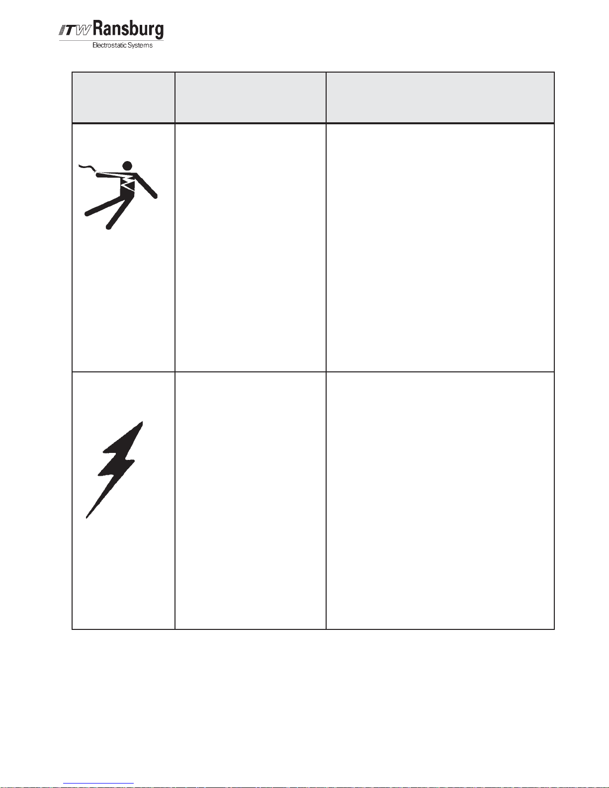
ElectricalElectrical
Electrical
ElectricalElectrical
EquipmentEquipment
Equipment
EquipmentEquipment
HAZARDHAZARD
HAZARD
HAZARDHAZARD
Tells what the hazard is.
High voltage equipment is utilized.
Arcing in areas of flammable or
combustible materials may occur.
Personnel are exposed to high
voltage during operation and
maintenance.
Protection against inadvertent
arcing that may cause a fire or
explosion is lost if safety circuits
are disabled during operation.
Frequent power supply shut-down
indicates a problem in the system
which requires correction.
An electrical arc can ignite coating
materials and cause a fire or
explosion.
SAFEGUARDSSAFEGUARDS
SAFEGUARDS
SAFEGUARDSSAFEGUARDS
Tells how to avoid the hazard.
The power supply, optional remote control cabinet,
and all other electrical equipment must be located
outside Class I or II, Division 1 and 2 hazardous
areas. Refer to NFPA No. 33, 2000 Edition.
Turn the power supply OFF before working on the
equipment.
Test only in areas free of flammable or combustible
material.
Testing may require high voltage to be on, but only
as instructed.
Production should never be done with the safety
circuits disabled.
Before turning the high voltage on, make sure no
objects are within the sparking distance.
Spray Area /Spray Area /
Spray Area /
Spray Area /Spray Area /
High VoltageHigh Voltage
High Voltage
High VoltageHigh Voltage
EquipmentEquipment
Equipment
EquipmentEquipment
This is a high voltage ungrounded
device that can produce electrical
arcs capable of igniting coating
materials.
Parts being sprayed must be supported on conveyors
or hangers and be grounded. The resistance between
the part and ground must not exceed 1 megohm.
(Reference NFPA Bulletin No. 33, 2000 Edition.)
A safe distance must be maintained between the
parts being coated and the atomizer bell. A distance
of at least 1 inch for each 10 kV of power supply output
voltage is required at all times.
Parts must be supported so that they will not swing
and reduce the clearance specified above.
All electrically conductive objects in the spray area,
with the exception of those objects required by the
process to be at high voltage, must be grounded.
Unless specifically approved for use in hazardous
locations, the power supply and other electrical
equipment must not be used in Class I, Division 1 or
2 locations.
LN-9214-00.2
33
3
33

Digital Node Adapter - Introduction
INTRODUCTIONINTRODUCTION
INTRODUCTION
INTRODUCTIONINTRODUCTION
GENERAL DESCRIPTIONGENERAL DESCRIPTION
GENERAL DESCRIPTION
GENERAL DESCRIPTIONGENERAL DESCRIPTION
Each Node Adapter Module can be characterized by the same basic block diagram. This
has three parts: (1) RIO interface, (2) central
processor, and (3) input/output circuits.
The RIO interface contains some Allen-Bradley
(A-B) components which are licensed to ITW.
These are designed specifically to communicate
with the proprietary protocol of the RIO serial
link. The central component of this block is an
application specific IC (ASIC) which is capable
of formatting the RIO information for use by the
central processor. The actual termination of the
RIO cable is made to an Interface Board at the
rear of the Node Adapter Module location. An
82 Ohm resistor is provided on the Interface
Board to terminate the RIO cable. Where the
RIO cable is daisy-chained to more than one
Node Adapter, only the last connection point in
the daisy-chain should be terminated by moving
the associated switch to the “TERM” position.
The core of the central processor is an 8032 microprocessor which communicates with the A-B
ASIC. The 8032 provides an RS-422 port from
which diagnostic functions are accomplished
via internal “debugger” software. The main software program, which includes the “debugger”
functions, is contained in an Erasable Programmable Read-Only Memory (EPROM). The
EPROM’s for each Node Adapter are of course
unique for its application.
SPECIFICASPECIFICA
SPECIFICA
SPECIFICASPECIFICA
Environmental / PhysicalEnvironmental / Physical
Environmental / Physical
Environmental / PhysicalEnvironmental / Physical
Temp. Operating:Temp. Operating:
Temp. Operating: 0o to 55oC
Temp. Operating:Temp. Operating:
Storage: Storage:
Storage: -40
Storage: Storage:
Humidity:Humidity:
Humidity: 95% Non-Condensing
Humidity:Humidity:
Size:Size:
Size: 100 x 160mm
Size:Size:
ConnectionsConnections
Connections
ConnectionsConnections
PLC I/O:PLC I/O:
PLC I/O: 3 position pluggable
PLC I/O:PLC I/O:
Module I/O:Module I/O:
Module I/O: 96-pin DIN 41612
Module I/O:Module I/O:
Diagnostic:Diagnostic:
Diagnostic: 10-pin flat cable connect-
Diagnostic:Diagnostic:
TIONSTIONS
TIONS
TIONSTIONS
o
C to 85oC
Eurocard module,
35mm wide
terminal strip on DAIF at
backplane connector
connector
or on DAIF
The RIO interface and central processor hardware
blocks for each Node Adapter are very similar.
The similarity ends at the input/output circuits, as
they are unique for each module. In each, some
data processing circuitry transfers information
between the central processor and the necessary
input/output devices. Depending on the Node
Adapter Module, these devices may be A/D
convertors, D/A convertors, data bus managers,
multiplexer or demultiplexers.
44
4
44
LN-9214-00.2

Digital Node Adapter - Introduction
ElectricalElectrical
Electrical
ElectricalElectrical
Power Required:Power Required:
Power Required: 24 VDC at 80 mA
Power Required:Power Required:
SIGNAL LEVELSSIGNAL LEVELS
SIGNAL LEVELS
SIGNAL LEVELSSIGNAL LEVELS
PLC I/O:PLC I/O:
PLC I/O: - Compatible with Allen-Bradley RIO
PLC I/O:PLC I/O:
- RIO termination resistor is switchable option on DAIF
DIGITAL MODE (Communication with 75119-02 Digital Module)DIGITAL MODE (Communication with 75119-02 Digital Module)
DIGITAL MODE (Communication with 75119-02 Digital Module)
DIGITAL MODE (Communication with 75119-02 Digital Module)DIGITAL MODE (Communication with 75119-02 Digital Module)
Output:Output:
Output: 5 V signal level: 8-bit data bus, 12 discrete outputs (10 Strobe, 2
Output:Output:
Lockout)
PLC I/O:PLC I/O:
PLC I/O:
PLC I/O:PLC I/O:
(Max. Mode): (Max. Mode):
(Max. Mode): Up to 82 points in output address, 3/4 logical rack
(Max. Mode): (Max. Mode):
(Min. Mode):(Min. Mode):
(Min. Mode): Up to 41 points in output address, 1/2 logical rack
(Min. Mode):(Min. Mode):
Application:Application:
Application:
Application:Application:
(Max. Mode): (Max. Mode):
(Max. Mode): DGNA communicates to up to five Digital Modules via 74847, mother
(Max. Mode): (Max. Mode):
board, and up to five additional Digital Modules in second 74847,
mother board, via DACAB. One DAIF (Digital configuration) is
required for each DGNA and one DACAB is used to connect between
DAIF and second mother board. The slot 5 and slot 10 Digital
Modules may be replaced by A10204-01, Discrete Modules, when
74787-00S, mother board, is used.
(Min. Mode):(Min. Mode):
(Min. Mode): DGNA communicates to up to five Digital Modules via 74847, mother
(Min. Mode):(Min. Mode):
board. One DAIF (Digital configuration) is required for each DGNA.
ATOMIZER MODEATOMIZER MODE
ATOMIZER MODE
ATOMIZER MODEATOMIZER MODE
Output:Output:
Output: 5 V signal level: 8-bit data bus, 30 discrete outputs (10 Strobe, 20
Output:Output:
Function Select)
0-10 V signal level: 20 analog outputs
PLC I/O:PLC I/O:
PLC I/O:
PLC I/O:PLC I/O:
(Max. Mode): (Max. Mode):
(Max. Mode): Up to 10 BTW (speed command), 30 BTR (status/speed feedback/
(Max. Mode): (Max. Mode):
pressure feedback), 1/2 logical rack
(Min. Mode):(Min. Mode):
(Min. Mode): Up to 5 BTW (speed command), 15 BTR (status/speed feedback/
(Min. Mode):(Min. Mode):
pressure feedback), 1/4 logical rack
Application:Application:
Application:
Application:Application:
(Max. Mode): (Max. Mode):
(Max. Mode): DGNA communicates to up to five 74944, Atomizer Modules, via
(Max. Mode): (Max. Mode):
74847, mother board, and up to five additional Atomizer Modules in a
second 74847, mother board, via DACB. One DAIF (Atomizer configuration) is required for each DGNA and one DACB is used to connect
between DAIF and second mother board.
(Min. Mode):(Min. Mode):
(Min. Mode): DGNA communicates to up to five 74944, Atomizer Modules, via
(Min. Mode):(Min. Mode):
74847, mother board. One DAIF (Atomizer configuration) is required
for each DGNA.
DIAGNOSTICDIAGNOSTIC
DIAGNOSTIC
DIAGNOSTICDIAGNOSTIC
RS-422 port, manual input/output capability, may be used as main
communication port
LN-9214-00.2
55
5
55
 Loading...