

REA III 100KVREA III 100KV
REA III 100KV
REA III 100KVREA III 100KV
SERVICE MANUAL
AA-82-01.3AA-82-01.3
AA-82-01.3
AA-82-01.3AA-82-01.3
(Replaces AA-82-01.2)
May - 2008
AUTAUT
AUT
AUTAUT
OMAOMA
OMA
OMAOMA
TIC APPLICATIC APPLICA
TIC APPLICA
TIC APPLICATIC APPLICA
TT
T
TT
OROR
OR
OROR
MODEL: 70393MODEL: 70393
MODEL: 70393
MODEL: 70393MODEL: 70393
IMPORIMPOR
IMPOR
IMPORIMPOR
carefully read SAFETY PRECAUTIONS,carefully read SAFETY PRECAUTIONS,
carefully read SAFETY PRECAUTIONS,
carefully read SAFETY PRECAUTIONS,carefully read SAFETY PRECAUTIONS,
starting on page 1, and all instructions instarting on page 1, and all instructions in
starting on page 1, and all instructions in
starting on page 1, and all instructions instarting on page 1, and all instructions in
this manual. Keep this Service Manual forthis manual. Keep this Service Manual for
this manual. Keep this Service Manual for
this manual. Keep this Service Manual forthis manual. Keep this Service Manual for
future reference.future reference.
future reference.
future reference.future reference.
TT
ANTANT
T
ANT
TT
ANTANT
: Before using this equipment,: Before using this equipment,
: Before using this equipment,
: Before using this equipment,: Before using this equipment,
Service Manual Price:Service Manual Price:
Service Manual Price: €
Service Manual Price:Service Manual Price:
25.00 (Euro)25.00 (Euro)
25.00 (Euro)
25.00 (Euro)25.00 (Euro)
$30.00 (U.S.)$30.00 (U.S.)
$30.00 (U.S.)
$30.00 (U.S.)$30.00 (U.S.)

NOTE:NOTE:
NOTE: This manual has been changed from revision
NOTE:NOTE:
AA-82-01.2 AA-82-01.2
AA-82-01.2 to revision
AA-82-01.2 AA-82-01.2
AA-82-01.3. AA-82-01.3.
AA-82-01.3.
AA-82-01.3. AA-82-01.3.
Reasons for this change are noted under “Manual Change Summary” inside the back cover of this
manual.
AA-82-01.3
CONTENTSCONTENTS
CONTENTS
CONTENTSCONTENTS
SAFETY:SAFETY:
SAFETY:
SAFETY:SAFETY:
REA III 100kV Automatic Applicator - Contents
PAGEPAGE
PAGE
PAGEPAGE
1-41-4
1-4
1-41-4
SAFETY PRECAUTIONS...........................................................................................................
HAZARDS/SAFEGUARDS.........................................................................................................
ATEXATEX
ATEX
ATEXATEX
EUROPEAN ATEX DIRECTIVE.................................................................................................
EUROPEAN ATEX LABELS.......................................................................................................
INTRODUCTION:INTRODUCTION:
INTRODUCTION:
INTRODUCTION:INTRODUCTION:
GENERAL DESCRIPTION.........................................................................................................
SPECIFICATIONS.......................................................................................................................
INSTALLATION:INSTALLATION:
INSTALLATION:
INSTALLATION:INSTALLATION:
INSTALLING................................................................................................................................
TYPICAL REA AUTOMATIC APPLICATOR
INSTALLATION - WATERBORNE.............................................................................................
ATOMIZER ASSEMBLY SELECTION.......................................................................................
OPERATION:OPERATION:
OPERATION:
OPERATION:OPERATION:
SAFETY PROCEDURES............................................................................................................
1
2-4
5-85-8
5-8
5-85-8
5
6-7
9-109-10
9-10
9-109-10
9
9
11-1411-14
11-14
11-1411-14
11-12
12-13
14
15-1815-18
15-18
15-1815-18
15-17
MAINTENANCE:MAINTENANCE:
MAINTENANCE:
MAINTENANCE:MAINTENANCE:
ROUTINE SCHEDULE...............................................................................................................
ATOMIZER ASSEMBLY CLEANING PROCEDURE................................................................
FLUSHING PROCEDURES.......................................................................................................
SERVICE.....................................................................................................................................
TROUBLESHOOTING GUIDE...................................................................................................
EVALUATING RESULTS OF SCI AND CURRENT
DEMAND TEST...........................................................................................................................
PARTS IDENTIFICATION:PARTS IDENTIFICATION:
PARTS IDENTIFICATION:
PARTS IDENTIFICATION:PARTS IDENTIFICATION:
70393 REA III 100KV AUTOMATIC APPLICATOR
EXPLODED VIEW.......................................................................................................................
70393 REA III AUTOMATIC APPLICATOR /
SOLVENTBORNE SYSTEMS PARTS LIST..............................................................................
70393 REA III AUTOMATIC APPLICATOR /
WATERBORNE SYSTEMS PARTS LIST..................................................................................
WARRANTY POLICIES:WARRANTY POLICIES:
WARRANTY POLICIES:
WARRANTY POLICIES:WARRANTY POLICIES:
LIMITED WARRANTY.................................................................................................................
19-3619-36
19-36
19-3619-36
19-20
21-22
22
22--32
33-34
35
37-4437-44
37-44
37-4437-44
37-38
39-40
41-43
4545
45
4545
45
AA-82-01.3
REA III 100kV Automatic Applicator - Safety
SAFETYSAFETY
SAFETY
SAFETYSAFETY
SAFETY PRECAUTIONSSAFETY PRECAUTIONS
SAFETY PRECAUTIONS
SAFETY PRECAUTIONSSAFETY PRECAUTIONS
W A R N I N GW A R N I N G
W A R N I N G
W A R N I N GW A R N I N G
!!
!
!!
Before operating, maintaining or servicing any
ITW Ransburg electrostatic coating system, read
and understand all of the technical and safety
literature for your ITW Ransburg products. This
manual contains information that is important for
you to know and understand. This information
relates to USER SAFETY and PREVENTING
EQUIPMENT PROBLEMS. To help you
recognize this information, we use the following
symbols. Please pay particular attention to these
sections.
AA
W W
ARNING!ARNING!
A
W
ARNING!
AA
W W
ARNING!ARNING!
to a situation that might cause serious injuryto a situation that might cause serious injury
to a situation that might cause serious injury
to a situation that might cause serious injuryto a situation that might cause serious injury
if instructions are not followed.if instructions are not followed.
if instructions are not followed.
if instructions are not followed.if instructions are not followed.
A CAUTION!A CAUTION!
A CAUTION!
A CAUTION!A CAUTION!
how to prevent damage to equipment or howhow to prevent damage to equipment or how
how to prevent damage to equipment or how
how to prevent damage to equipment or howhow to prevent damage to equipment or how
to avoid a situation that might cause minorto avoid a situation that might cause minor
to avoid a situation that might cause minor
to avoid a situation that might cause minorto avoid a situation that might cause minor
injuryinjury
injury
injuryinjury
A NOTE is information relevant to theA NOTE is information relevant to the
A NOTE is information relevant to the
A NOTE is information relevant to theA NOTE is information relevant to the
procedure in progress.procedure in progress.
procedure in progress.
procedure in progress.procedure in progress.
While this manual lists standard specifications and
service procedures, some minor deviations may
be found between this literature and your
equipment. Differences in local codes and plant
requirements, material delivery requirements, etc.,
make such variations inevitable. Compare this
manual with your system installation drawings and
appropriate ITW Ransburg equipment
manuals to reconcile such differences.
..
.
..
states information to alert youstates information to alert you
states information to alert you
states information to alert youstates information to alert you
states information that tellsstates information that tells
states information that tells
states information that tellsstates information that tells
> The user
the Safety Section in this manual and the
ITW Ransburg safety literature therein identified.
> This manual
understood by
clean or maintain this equipment! Special
care should be taken to ensure that the
WARNINGSWARNINGS
WARNINGS and safety requirements for
WARNINGSWARNINGS
operating and servicing the equipment are
followed. The user should be aware of and
adhere to
and ordinances as well as
SAFETY STANDARD, SAFETY STANDARD,
SAFETY STANDARD, prior to installing,
SAFETY STANDARD, SAFETY STANDARD,
operating, and/or servicing this equipment.
MUSTMUST
MUST read and be familiar with
MUSTMUST
MUSTMUST
MUST be read and thoroughly
MUSTMUST
ALLALL
ALL personnel who operate,
ALLALL
ALLALL
ALL local building and fire codes
ALLALL
NFPA-33NFPA-33
NFPA-33
NFPA-33NFPA-33
W A R N I N GW A R N I N G
W A R N I N G
W A R N I N GW A R N I N G
!!
!
!!
> The hazards shown on the following page
may occur during the normal use of this
equipment. Please read the hazard chart
beginning on page 2.
Careful study and continued use of this manual
will provide a better understanding of the
equipment and process, resulting in more efficient
operation, longer trouble-free service and faster
easier troubleshooting. If you do not have the
manuals and safety literature for your Ransburg
system, contact your local ITW Ransburg
representative or ITW Ransburg.
11
1
11
,
AA-82-01.3
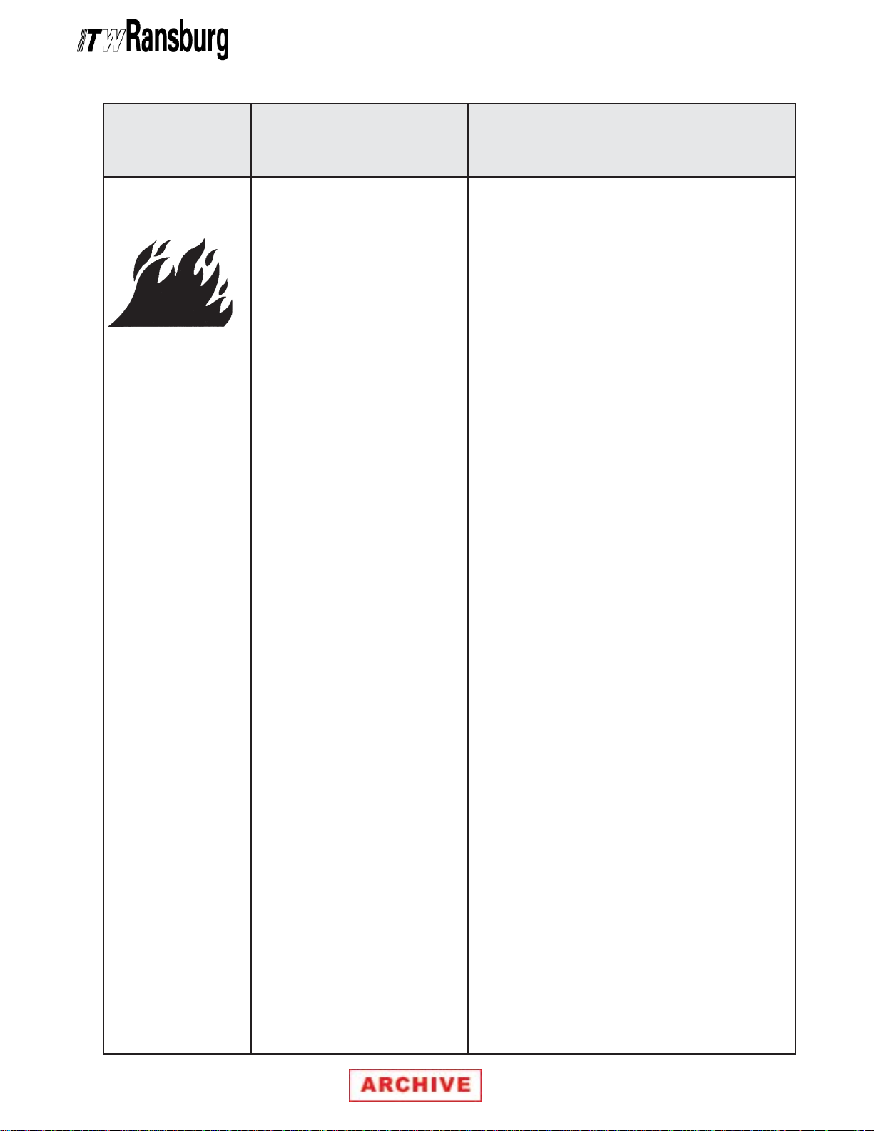
AREAAREA
AREA
AREAAREA
Tells where hazards
may occur.
HAZARDHAZARD
HAZARD
HAZARDHAZARD
Tells what the hazard is.
REA III 100kV Automatic Applicator - Safety
SAFEGUARDSSAFEGUARDS
SAFEGUARDS
SAFEGUARDSSAFEGUARDS
Tells how to avoid the hazard.
Spray AreaSpray Area
Spray Area
Spray AreaSpray Area
Fire Hazard
Improper or inadequate operation
and maintenance procedures will
cause a fire hazard.
Protection against inadvertent
arcing that is capable of causing
fire or explosion is lost if any
safety interlocks are disabled
during operation. Frequent power
supply shutdown indicates a
problem in the system requiring
correction.
Fire extinguishing equipment must be present in the
spray area and tested periodically.
Spray areas must be kept clean to prevent the
accumulation of combustible residues.
Smoking must never be allowed in the spray area.
The high voltage supplied to the atomizer must be
turned off prior to cleaning, flushing or maintenance.
When using solvents for cleaning:
Those used for equipment flushing should have flash
points equal to or higher than those of the coating
material.
Those used for general cleaning must have flash
points above 100oF (37.8oC).
Spray booth ventilation must be kept at the rates
required by NFPA-33, OSHA, and local codes. In
addition, ventilation must be maintained during
cleaning operations using flammable or combustible
solvents.
Electrostatic arcing must be prevented.
Test only in areas free of combustible material.
Testing may require high voltage to be on, but only
as instructed.
Non-factory replacement parts or unauthorized
equipment modifications may cause fire or injury.
If used, the key switch bypass is intended for use
only during setup operations. Production should
never be done with safety interlocks disabled.
Never use equipment intended for use in waterborne
installations to spray solvent based materials.
The paint process and equipment should be set up
and operated in accordance with NFPA-33, NEC, and
OSHA requirements.
AA-82-01.3
22
2
22
REA III 100kV Automatic Applicator - Safety
AREAAREA
AREA
AREAAREA
Tells where hazards
may occur.
General Use andGeneral Use and
General Use and
General Use andGeneral Use and
MaintenanceMaintenance
Maintenance
MaintenanceMaintenance
ElectricalElectrical
Electrical
ElectricalElectrical
EquipmentEquipment
Equipment
EquipmentEquipment
HAZARDHAZARD
HAZARD
HAZARDHAZARD
Tells what the hazard is.
Improper operation or maintenance
may create a hazard.
Personnel must be properly trained
in the use of this equipment.
High voltage equipment is utilized. Arcing in areas of
flammable or combustible
materials may occur. Personnel
are ex-posed to high voltage during
operation and maintenance.
Protection against inadvertent
arcing that may cause a fire or
explosion is lost if safety circuits
are disabled during operation.
Frequent power supply shutdown
indicates a problem in the system
which requires correction.
An electrical arc can ignite coating materials and cause a fire or
explosion.
SAFEGUARDSSAFEGUARDS
SAFEGUARDS
SAFEGUARDSSAFEGUARDS
Tells how to avoid the hazard.
Personnel must be given training in accordance with
the requirements of NFPA-33.
Instructions and safety precautions must be read and
understood prior to using this equipment.
Comply with appropriate local, state, and national
codes governing ventilation, fire protection, operation
maintenance, and housekeeping. Reference OSHA,
NFPA-33, and your insurance company requirements.
The power supply, optional remote control cabinet,
and all other electrical equipment must be located
outside Class I or II, Division 1 and 2 hazardous
areas. Refer to NFPA-33.
Turn the power supply OFF before working on the
equipment.
Test only in areas free of flammable or combustible
material.
Testing may require high voltage to be on, but only
as instructed.
Production should never be done with the safety
circuits disabled.
Before turning the high voltage on, make sure no
objects are within the sparking distance.
33
3
33
AA-82-01.3
REA III 100kV Automatic Applicator - Safety
AREAAREA
AREA
AREAAREA
Tells where hazards
may occur.
Spray Area /Spray Area /
Spray Area /
Spray Area /Spray Area /
High VoltageHigh Voltage
High Voltage
High VoltageHigh Voltage
EquipmentEquipment
Equipment
EquipmentEquipment
HAZARDHAZARD
HAZARD
HAZARDHAZARD
Tells what the hazard is.
This is a high voltage device that
can produce electrical arcs
capable of igniting coating
materials.
SAFEGUARDSSAFEGUARDS
SAFEGUARDS
SAFEGUARDSSAFEGUARDS
Tells how to avoid the hazard.
Parts being sprayed must be supported on conveyors
or hangers and be grounded. The resistance between
the part and ground must not exceed 1 megohm.
(Reference NFPA-33.)
A safe distance must be maintained between the parts
being coated and the atomizer bell. A distance of at
least 1 inch for each 10 KV of power supply output
voltage is required at all times.
Parts must be supported so that they will not swing
and reduce the clearance specified above.
All electrically conductive objects in the spray area,
with the exception of those objects required by the
process to be at high voltage, must be grounded.
Unless specifically approved for use in hazardous
locations, the power supply and other electrical
equipment must not be used in Class I, Division 1 or
2 locations.
AA-82-01.3
44
4
44

REA III 100kV Automatic Applicator - Atex
EUROPEAN AEUROPEAN A
EUROPEAN A
EUROPEAN AEUROPEAN A
The following instructions apply to equipment
covered by certificate number Sira 08ATEX5040X:
1. The equipment may be used with flammable
gases and vapors with apparatus groups II and
with temperature class T6.
2. The equipment is only certified for use in
ambient temperatures in the range +12.8°C to
+40°C and should not be used outside this range.
3. Installation shall be carried out by suitably
trained personnel in accordance with the
applicable code of practice e.g. EN 6007914:1997.
4. Inspection and maintenance of this equipment
shall be carried out by suitably trained personnel
in accordance with the applicable code of practice
e.g. EN 60079-17.
5. Repair of this equipment shall be carried out by
suitable trained personnel in accordance with the
applicable code of practice e.g. EN 60079-19.
6. Putting into service, use, assembling, and
adjustment of the equipment shall be fitted by
suitably trained personnel in accordance with the
manufacturer's documentation.
Refer to the "Table of Contents" of this service
manual:
a. Installation
b. Operation
c. Maintenance
d. Parts Identification
7. Components to be incorporated into or used as
replacement parts of the equipment shall be fitted
by suitably trained personnel in accordance with
the manufacturer's documentation.
TEX DIRECTIVE 94/9/EC, ANNEX II, 1.0.6TEX DIRECTIVE 94/9/EC, ANNEX II, 1.0.6
TEX DIRECTIVE 94/9/EC, ANNEX II, 1.0.6
TEX DIRECTIVE 94/9/EC, ANNEX II, 1.0.6TEX DIRECTIVE 94/9/EC, ANNEX II, 1.0.6
8. The certification of this equipment relies upon
the following materials used in its construction:
If the equipment is likely to come into contact with
aggressive substances, then it is the
responsibility of the user to take suitable
precautions that prevent it from being adversely
affected, thus ensuring that the type of protection
provided by the equipment is not compromised.
Aggressive substances: e.g. acidic liquids or
gases that may attack metals, or solvents that
may affect polymeric materials.
Suitable precautions: e.g. regular checks as part
of routine inspections or establishing from the
material's data sheets that it is resistant to specific
chemicals.
Refer to "Specifications" in the "Introduction"
section:
a. All fluid passages contain stainless steel
or nylon fittings.
b. High voltage cascade is encapsulated with
a solvent resistant epoxy.
9. A recapitulation of the certification marking is
detailed in the "Atex" section, on the next page,
drawing numbers: 19688, 72562, 76454, 76854,
76896, 77059, 78886, 78894-04, and LEPS5016.
10. The characteristics of the equipment shall be
detailed e.g. electrical, pressure, and voltage
parameters.
The manufacturer should note that, on beingThe manufacturer should note that, on being
The manufacturer should note that, on being
The manufacturer should note that, on beingThe manufacturer should note that, on being
put into service, the equipment must beput into service, the equipment must be
put into service, the equipment must be
put into service, the equipment must beput into service, the equipment must be
accompanied by a translation of theaccompanied by a translation of the
accompanied by a translation of the
accompanied by a translation of theaccompanied by a translation of the
instructions in the language or languagesinstructions in the language or languages
instructions in the language or languages
instructions in the language or languagesinstructions in the language or languages
of the country in which the equipment is toof the country in which the equipment is to
of the country in which the equipment is to
of the country in which the equipment is toof the country in which the equipment is to
be used and by the instructions in thebe used and by the instructions in the
be used and by the instructions in the
be used and by the instructions in thebe used and by the instructions in the
original language.original language.
original language.
original language.original language.
55
5
55
AA-82-01.3
REA III 100kV AutomaticREA III 100kV Automatic
REA III 100kV Automatic
REA III 100kV AutomaticREA III 100kV Automatic
Applicator 70393 AApplicator 70393 A
Applicator 70393 A
Applicator 70393 AApplicator 70393 A
Marking DefinitionsMarking Definitions
Marking Definitions
Marking DefinitionsMarking Definitions
Ex Certificate Number: Sira 08ATEX5040X
Sira = Notified Body performing EC-type
examination
08 = Year of certification
ATEX = Reference to ATEX Directive
5 = Protection Concept Code (code 5 is titled
Encapsulation)
040 = Document serial number
X = Special conditions for safe use apply
Special conditions for safe use: The REA-III 70393
Automatic Applicator shall only be used with
associated 76447-XX, 76045-XX, LEPS5000-04,
LEPS-5002-00, and 78789-02 HV Control Units.
TEX ProductTEX Product
TEX Product
TEX ProductTEX Product
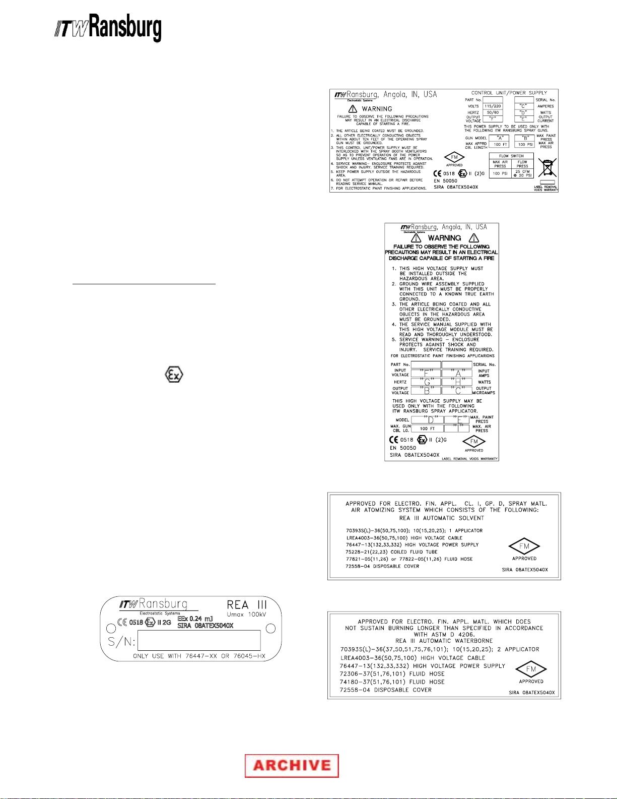
REA III 100kV Automatic Applicator - Atex
Label 72562Label 72562
Label 72562
Label 72562Label 72562
Label 76454Label 76454
Label 76454
Label 76454Label 76454
Product MarkingProduct Marking
Product Marking
Product MarkingProduct Marking
II 2 GII 2 G
II 2 G
II 2 GII 2 G
Ex = Specific marking of explosive protection
II = Equipment Group hazardous area characteristics
2 = Equipment Category
G = Type of explosive atmosphere (gases, vapors,
or mists)
EEx 0.24mJEEx 0.24mJ
EEx 0.24mJ = The REA-III 70393 Automatic
EEx 0.24mJEEx 0.24mJ
Applicator is suitable for use in automatic spraying
installations complying with EN 50050 as they are
a Type A class with a discharge energy limit of
0.24mJ.
Label 19688Label 19688
Label 19688
Label 19688Label 19688
Label 76854Label 76854
Label 76854
Label 76854Label 76854
Label 76896Label 76896
Label 76896
Label 76896Label 76896
AA-82-01.3
66
6
66
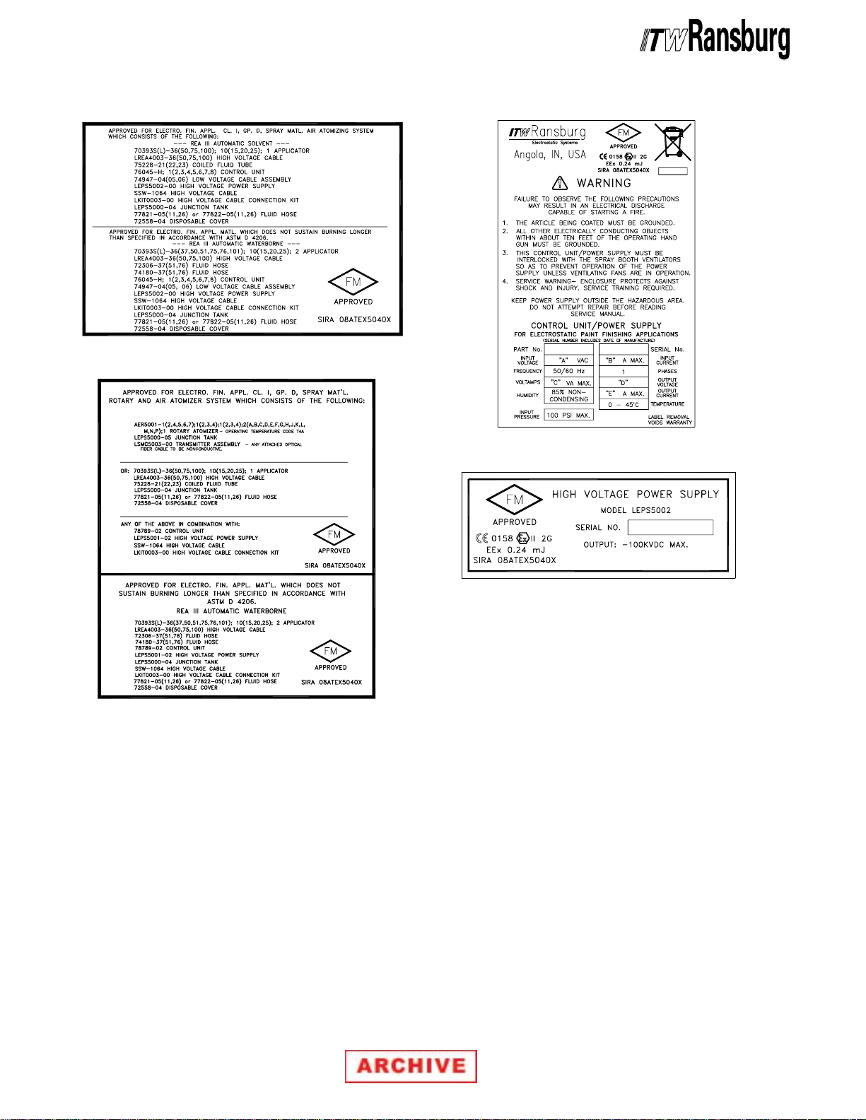
REA III 100kV Automatic Applicator - Atex
Label 77059Label 77059
Label 77059
Label 77059Label 77059
Label 78886Label 78886
Label 78886
Label 78886Label 78886
Label 78894-04Label 78894-04
Label 78894-04
Label 78894-04Label 78894-04
Label LEPS0016Label LEPS0016
Label LEPS0016
Label LEPS0016Label LEPS0016
77
7
77
AA-82-01.3

REA III 100kV Automatic Applicator - Atex
NOTESNOTES
NOTES
NOTESNOTES
AA-82-01.3
88
8
88

REA III 100kV Automatic Applicator - Introduction
INTRODUCTIONINTRODUCTION
INTRODUCTION
INTRODUCTIONINTRODUCTION
GENERAL DESCRIPTIONGENERAL DESCRIPTION
GENERAL DESCRIPTION
GENERAL DESCRIPTIONGENERAL DESCRIPTION
REA III 100kV Automatic ApplicatorREA III 100kV Automatic Applicator
The
REA III 100kV Automatic Applicator
REA III 100kV Automatic ApplicatorREA III 100kV Automatic Applicator
applies a high voltage charge to the coating materials at the point of atomization using a 100kV
power supply. This electrostatic charge allows a
more efficient, uniform application of coating material to the front, edges, sides, and back of products, making it highly suitable for applying a wide
range of coatings to a variety of surface configurations: large targets, small parts, tubular wares,
concave and recessed parts, etc. It is available as
a grounded fluid system for solvent reduced coatings such as enamels, lacquers, epoxys, etc.
SPECIFICASPECIFICA
SPECIFICA
SPECIFICASPECIFICA
Environmental / PhysicalEnvironmental / Physical
Environmental / Physical
Environmental / PhysicalEnvironmental / Physical
Operating VOperating V
Operating V
Operating VOperating V
Operating FluidOperating Fluid
Operating Fluid
Operating FluidOperating Fluid
Pressure:Pressure:
Pressure: 0-100 psi (0-6.9 bar)
Pressure:Pressure:
Operating AirOperating Air
Operating Air
Operating AirOperating Air
Pressure:Pressure:
Pressure: 0-100 psi (0-6.9 bar)
Pressure:Pressure:
Flow Rate:Flow Rate:
Flow Rate: 1000 cc/min. maximum
Flow Rate:Flow Rate:
TIONSTIONS
TIONS
TIONSTIONS
oltage:oltage:
oltage: 100kV maximum
oltage:oltage:
(viscosity dependent)
One of the many safety features of the REA III 100
kV Automatic Applicator is the capability of limiting, to a desirable level, the electrical discharge
which is available from the charging electrode.
When organic solvent base paints are being
sprayed, this level must not exceed 0.25 mJ of
energy. In order to achieve this limitation, it is
necessary to prevent any flow of energy from the
paint supply through the paint line to the applicator
electrode. This is accomplished by grounding the
paint line at the applicator.
Short CircuitShort Circuit
Short Circuit
Short CircuitShort Circuit
Current:Current:
Current: 150 Microamperes
Current:Current:
Air and Fluid Nozzles:Air and Fluid Nozzles:
Air and Fluid Nozzles:
Air and Fluid Nozzles:Air and Fluid Nozzles:
Any ITW Ransburg Air and Fluid Nozzle
combination. (See “Nozzle Selection” in the
“Operation” section.)
Optional Hose andOptional Hose and
Optional Hose and
Optional Hose andOptional Hose and
Cable Lengths: Cable Lengths:
Cable Lengths: 25, 36, 50, 75, and 100 ft.
Cable Lengths: Cable Lengths:
(8m, 11m, 15m, 23m, and
31m)
99
9
99
AA-82-01.3

REA III 100kV Automatic Applicator - Introduction
NOTESNOTES
NOTES
NOTESNOTES
AA-82-01.3
1010
10
1010
REA III 100kV Automatic Applicator - Installation
INSTINST
INST
INSTINST
> Installation of the equipment
compliance with all Federal, State, Local and
National codes.
> The power supply
OUTSIDEOUTSIDE
OUTSIDE of the spray area.
OUTSIDEOUTSIDE
> Personnel
prevent a shock or spark during electrostatic
operation.
> Install and route the hoses and cables so
they are
excess of 120°F (49°C) and so that all hose
and cable bends are
(15 cm) radius. Failure to comply with these
parameters could cause equipment malfunctions that might create
DITIONS!DITIONS!
DITIONS!
DITIONS!DITIONS!
INSTINST
INST
INSTINST
1. To connect the high voltage cable, remove the
cable retainer bracket and remove the protective
cap for the power supply high voltage cable
socket. Insert the high voltage cable (and plug)
into socket. Gently hand-tighten the cable
retaining nut. Reattach the bracket.
2. The control unit
conduit with an explosion-proof terminal on or near
the spray booth where it will be convenient, or
may be connected with a line cord depending upon
application requirement.
ALLAALLA
ALLA
ALLAALLA
W A R N I N GW A R N I N G
W A R N I N G
W A R N I N GW A R N I N G
!!
!
!!
NOTNOT
NOT exposed to temperatures in
NOTNOT
ALLINGALLING
ALLING
ALLINGALLING
TIONTION
TION
TIONTION
MUSTMUST
MUST be in
MUSTMUST
MUST MUST
MUST be located
MUST MUST
MUSTMUST
MUST be
MUSTMUST
MAMA
MA
MAMA
GROUNDEDGROUNDED
GROUNDED to
GROUNDEDGROUNDED
NOTNOT
NOT less than a 6-inch
NOTNOT
HAZARDOUS CON-HAZARDOUS CON-
HAZARDOUS CON-
HAZARDOUS CON-HAZARDOUS CON-
YY
Y be connected through
YY
W A R N I N GW A R N I N G
W A R N I N G
W A R N I N GW A R N I N G
!!
!
!!
> The power supply
outside of the spray area. Install units in
accordance with the requirements of local
regulations.
3. Install Filters: Install the optional fluid filter on
output of fluid supply. Detail depends on whether
pressure tank, pump unit, recirculating system,
etc. is used. Filter must be installed vertically with
drain valve down and arrow pointing in direction
of flow (see Figure 1).
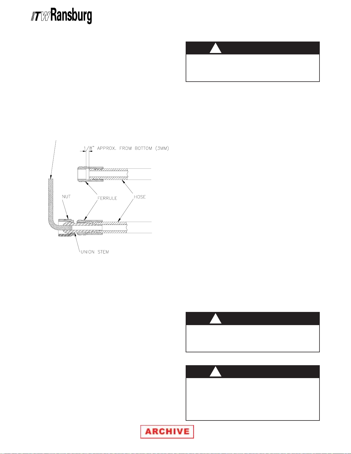
4. Install Line Hose (Air or Fluid):
> ITW Ransburg supplies a standard
25 ft. (8m) hose. Optional hose lengths of
36 ft. (11m), 50 ft. (15m), 75 ft. (23m), and
100 ft. (31m) are available. To meet
various length requirements, the hose
fitting on one end has not been attached.
Determine the hose length that is needed
and cut the hose. Attach the other fitting
as follows:
a. Lubricate all fittings with petroleum jelly.
b. Screw ferrule counter-clockwise onto hose
until it bottoms. Then back it off about 1/8inch (3mm).
MUSTMUST
MUST be located
MUSTMUST
NOTENOTE
NOTE
NOTENOTE
NOTENOTE
NOTE
NOTENOTE
NOTENOTE
NOTE
NOTENOTE
> Refer to the Power Supply Service
Manual for the circuit diagram and instructions to connect the power supply.
11
11
1
1
11
11
> The union stem will not seat if the hose
is bottomed against the ferrule.
AA-82-01.3
REA III 100kV Automatic Applicator - Installation
c. Install nut over union stem and start the stem
into the hose.
d. Using the 1/8-inch Allen wrench, screw the
union stem into the hose until it bottoms
against the ferrule.
e. Connect one end of one hose to the appro-
priate fitting on the bottom of the applicator
body and the other end to the power supply
pressure switch for trigger air. Attach the
other hose to the atomizing air source.
W A R N I N GW A R N I N G
W A R N I N G
W A R N I N GW A R N I N G
!!
!
!!
NEVERNEVER
>
NEVER use wooden boxes, pallets, or
NEVERNEVER
boards as wood will absorb moisture and is a
poor insulator.
• Isolation stand
from the grounded booth wall, chain link fence,
or other grounded objects.
• Air hoses to the pressure pot or pump on the
insulating stand should be nonconductive. Many
rubber hoses will have static grounding circuits
or carbon content and are
• Air regulators for pots or pumps should be
mounted remotely outside the fence or cage
area to facilitate changes in pressure without
shutting the system down.
• Grounding hooks at the cage
to ground portions of the system when
personnel are working close by.
MUST MUST
MUST be at least 18-inches
MUST MUST
NOTNOT
NOT suitable.
NOTNOT
MUSTMUST
MUST be used
MUSTMUST
Figure 1: Installing Line HoseFigure 1: Installing Line Hose
Figure 1: Installing Line Hose
Figure 1: Installing Line HoseFigure 1: Installing Line Hose
TYPICAL REATYPICAL REA
TYPICAL REA
TYPICAL REATYPICAL REA
AUTAUT
AUT
AUTAUT
INSTINST
INST
INSTINST
WW
W
WW
Using waterborne coating with electrostatic
equipment requires that the fluid source should
be isolated from ground and other precautions be
taken to ensure operator safety and system
efficiency. The following guidelines should be
followed:
• The fluid lines and source
OMAOMA
OMA
OMAOMA
ALLAALLA
ALLA
ALLAALLA
AA
TERBORNETERBORNE
A
TERBORNE
AA
TERBORNETERBORNE
from ground. An isolating paint stand or similar
isolating (non-porous) material
TIC APPLICATIC APPLICA
TIC APPLICA
TIC APPLICATIC APPLICA
TION -TION -
TION -
TION -TION -
MUSTMUST
MUST be isolated
MUSTMUST
MUSTMUST
MUST be used.
MUSTMUST
TT
T
TT
OROR
OR
OROR
• Fluid lines to the applicator
from scraping and abrasion on the floor or sharp
metal edges that could lead to voltage pinholing
and loss of kV on the charged system.
• Cleanliness and maintenance are extremely
critical.
• Fully discharge system capacitance prior to
service.
W A R N I N GW A R N I N G
W A R N I N G
W A R N I N GW A R N I N G
!!
!
!!
> System capacitance must be fully dis-
charged prior to any service or maintenance of
the applicator.
W A R N I N GW A R N I N G
W A R N I N G
W A R N I N GW A R N I N G
!!
!
!!
> ALL charged (isolated) systems
inside a fence or cage to prevent contact by
personnel. An interlock system
provided that interrupts high voltage flow to the
applicator if the gate is opened.
MUSTMUST
MUST be protected
MUSTMUST
MUSTMUST
MUST be
MUSTMUST
MUSTMUST
MUST be
MUSTMUST
AA-82-01.3
1212
12
1212

REA III 100kV Automatic Applicator - Installation
Paint PreparationPaint Preparation
Paint Preparation
Paint PreparationPaint Preparation
A proper paint mixture is essential to electrostatic
operation. Paint test equipment may be obtained
through your ITW Ransburg representative.
Consult ITW Ransburg literature “Paint Related
Information for REA and REM Applicators” manual
for paint formulation information. For further paint
formulation and testing procedures, consult your
ITW Ransburg representative and/or paint
supplier.
Atomizer Assembly SelectionAtomizer Assembly Selection
Atomizer Assembly Selection
Atomizer Assembly SelectionAtomizer Assembly Selection
The “Atomizer Assembly Selection” charts are
provided to give you a comparison of the air caps
and fluid nozzles.
AA
TT
OMIZER ASSEMBLOMIZER ASSEMBL
A
T
OMIZER ASSEMBL
AA
TT
OMIZER ASSEMBLOMIZER ASSEMBL
DEPEND ON QUALITIES DESIRED ANDDEPEND ON QUALITIES DESIRED AND
DEPEND ON QUALITIES DESIRED AND
DEPEND ON QUALITIES DESIRED ANDDEPEND ON QUALITIES DESIRED AND
MUST BE VERIFIED BY ACTUAL TRIAL.MUST BE VERIFIED BY ACTUAL TRIAL.
MUST BE VERIFIED BY ACTUAL TRIAL.
MUST BE VERIFIED BY ACTUAL TRIAL.MUST BE VERIFIED BY ACTUAL TRIAL.
See you authorized ITW Ransburg distributor for
atomizer demonstration.
THE CHOICE OFTHE CHOICE OF
THE CHOICE OF
THE CHOICE OFTHE CHOICE OF
YY
SHOULD SHOULD
Y
SHOULD
YY
SHOULD SHOULD
> A counter-clockwise turn of the air cap
may loosen the fluid nozzle and cause air to
get into the paint or paint to cross over into
the air passages.
Applicator TApplicator T
Applicator T
Applicator TApplicator T
Mount the applicator 6-12-inches (152-305mm)
maximum from the target for best operation.
C A U T I O NC A U T I O N
C A U T I O N
C A U T I O NC A U T I O N
!!
!
!!
o To T
arget Distancearget Distance
o T
arget Distance
o To T
arget Distancearget Distance
Spray Pattern AdjustmentSpray Pattern Adjustment
Spray Pattern Adjustment
Spray Pattern AdjustmentSpray Pattern Adjustment
The spray pattern of fan atomizers is adjustable
from a small circle to an elongated oval,
approximately 10-12-inches (254-305mm) across
the useable long axis at 8-10-inches (203-254mm)
from the target. The swirl atomizer assemblies
produce a round pattern from 5-9-inches (127229mm) in diameter. To adjust pattern size,
increasing fan air pressure will expand the pattern,
a reduction will decrease it. To change the spray
pattern axis of fan atomizers from horizontal to
vertical, loosen retainer ring, rotate the air cap
clockwise to the desired position, and gently
tighten the ring.
1313
13
1313
AA-82-01.3

ATAT
OMIZER ASSEMBLOMIZER ASSEMBL
AT
OMIZER ASSEMBL
ATAT
OMIZER ASSEMBLOMIZER ASSEMBL
REA III 100kV Automatic Applicator - Installation
YY
SELECTION SELECTION
Y
SELECTION
YY
SELECTION SELECTION
REA NOZZLESREA NOZZLES
REA NOZZLES
REA NOZZLESREA NOZZLES
(Conventional Spray)(Conventional Spray)
(Conventional Spray)
(Conventional Spray)(Conventional Spray)
Air CapAir Cap
Air Cap
Air CapAir Cap
Part Part
Part
Part Part
NumberNumber
Number
NumberNumber
70899-00 70898-00 Swirl 4903-00 74963-02
LREA0002 LREA0003 Round 73569-00 74963-02
4904-65R 4907-44 .055” (1.4mm) 73569-00 74963-02
4904-65R 4907-45 .070” (1.8mm) 73569-00 74963-02
4904-65R 4907-46 .042” (1.1mm) 73569-00 74963-02
4904-65R 4907-47 .028” (0.7mm) 73569-00 74963-02
4904-65R 4907-48 .047” (1.2mm) 73569-00 74963-02
4904-63 4907-44 .055” (1.4mm) 73569-00 74963-02
4904-63 4907-45 .070” (1.8mm) 73569-00 74963-02
4904-63 4907-46 .042” (1.1mm) 73569-00 74963-02
4904-63 4907-47 .028” (0.7mm) 73569-00 74963-02
4904-63 4907-48 .047” (1.2mm) 73569-00 74963-02
4904-98 4907-44 .055” (1.4mm) 73569-00 74963-02
4904-98 4907-45 .070” (1.8mm) 73569-00 74963-02
4904-98 4907-46 .042” (1.1mm) 73569-00 74963-02
4904-98 4907-47 .028” (0.7mm) 73569-00 74963-02
4904-98 4907-48 .047” (1.2mm) 73569-00 74963-02
Fluid Nozzle Fluid Nozzle
Fluid Nozzle
Fluid Nozzle Fluid Nozzle
Part Number Part Number
Part Number
Part Number Part Number
Orifice Orifice
Orifice
Orifice Orifice
IDID
ID
IDID
Separate Separate
Separate
Separate Separate
Retaining Retaining
Retaining
Retaining Retaining
Ring Ring
Ring
Ring Ring
PressurePressure
Pressure
PressurePressure
Reducer Reducer
Reducer
Reducer Reducer
(Black)(Black)
(Black)
(Black)(Black)
REA NOZZLESREA NOZZLES
REA NOZZLES
REA NOZZLESREA NOZZLES
(HVLP)(HVLP)
(HVLP)
(HVLP)(HVLP)
Air CapAir Cap
Air Cap
Air CapAir Cap
Part Part
Part
Part Part
NumberNumber
Number
NumberNumber
75601-00 75600-01 .055” (1.4mm) 73569-00 74963-03
75601-00 75600-02 .070” (1.8mm) 73569-00 74963-03
75601-00 75600-03 .086” (2.2mm) 73569-00 74963-03
AA-82-01.3
Fluid Nozzle Fluid Nozzle
Fluid Nozzle
Fluid Nozzle Fluid Nozzle
Part Number Part Number
Part Number
Part Number Part Number
Orifice Orifice
Orifice
Orifice Orifice
ID ID
ID
ID ID
Separate Separate
Separate
Separate Separate
Retaining Retaining
Retaining
Retaining Retaining
Ring Ring
Ring
Ring Ring
Pressure Pressure
Pressure
Pressure Pressure
Reducer Reducer
Reducer
Reducer Reducer
(White)(White)
(White)
(White)(White)
1414
14
1414

REA III 100kV Automatic Applicator - Operation
OPERAOPERA
OPERA
OPERAOPERA
SAFETY PROCEDURESSAFETY PROCEDURES
SAFETY PROCEDURES
SAFETY PROCEDURESSAFETY PROCEDURES
!!
!
!!
> The simple safety measures outlined in the
“Safety” section are vital. Failure to observe
them could cause a spark capable of starting
a fire.
1. The articles being coated
at all times.
2. All components of the applicator system
be grounded at all times.
3. All contact points
accumulation of non-conductive residue.
4. All electrically conductive objects, especially
solvent containers, within the spray area
be either removed or grounded.
TIONTION
TION
TIONTION
W A R N I N GW A R N I N G
W A R N I N G
W A R N I N GW A R N I N G
MUSTMUST
MUST be grounded
MUSTMUST
MUSTMUST
MUST be free of any
MUSTMUST
MUSTMUST
MUST
MUSTMUST
MUSTMUST
MUST
MUSTMUST
Additional cards summarizing these safety
requirements are available from ITW Ransburg
on request. These cards should be posted in the
spraying area so that they can be readily referred
to and serve as a reminder to personnel that area
of responsibility. Additional copies of “Cleaning
Safety Requirements” are available upon request.
Each user should examine his own coating
operation, develop his own safety program and
ensure that his workers follow correct procedures.
ITW Ransburg hopes that the information it
provides is helpful to the user in establishing such
a program.
In addition to the available cards, labels, brochures,
and service manuals, the user should consult
other standards and recognized safety authorities.
Local codes and authorities also have standards
to be followed in the operation of your spray
equipment. Your insurance carrier will be helpful
in answering questions that arise in your
development of spray coating procedures.
Any tool, if used improperly, can be dangerous.
Safety is ultimately the responsibility of those using
a tool. In like manner, safe operation of
electrostatic coating processes is the
responsibility of those who use such processes
and those who operate electrostatic coating
equipment. It is most important that equipment
operators and supervisory personnel understand
the requirements for safe operations.
W A R N I N GW A R N I N G
W A R N I N G
W A R N I N GW A R N I N G
!!
!
!!
ANYANY
> If
ANY symptom of improper operation
ANYANY
occurs suspend use of the unit until the problem has been diagnosed and corrected. See
the appropriate “Troubleshooting Guide” or
contact your ITW Ransburg representative.
All personnel MUST read and understand the
“T“T
following ITW Ransburg literature,
Supplement for All Products”.Supplement for All Products”.
Supplement for All Products”.
Supplement for All Products”.Supplement for All Products”.
echnicalechnical
“T
echnical
“T“T
echnicalechnical
1515
15
1515
AA-82-01.3

REA III 100kV Automatic Applicator - Operation
W A R N I N GW A R N I N G
W A R N I N G
W A R N I N GW A R N I N G
!!
!
!!
> Verify that the applicator body assembly is
actually grounded before operating it! This is
done with a fully connected and operation
system, by placing one lead of an ohm meter
to the body assembly and the other to the
building electrical ground (cold water pipe,
building structure, etc.). The reading should
be essentially zero.
> If a reading much greater than zero is
obtained, check that the power supply is
grounded. Place one lead of the ohm meter on
the building electrical ground and the other on
the high voltage cable outlet bushing. If the
reading is much greater than zero, reconnect
the power supply ground. If the meter reads
zero, check the high voltage cable. Place one
lead on the high voltage cable retaining nut and
the other lead on the applicator body assembly. If the reading is much greater than zero,
the braided cable may be defective and should
be replaced.
1. Parts, Equipment and Supplies:
a. Ground the spray booth, the paint tank,
and the conveyor.
2. Personel Procedures:
GROUND ALL PERSONS IN ALLGROUND ALL PERSONS IN ALL
a.
GROUND ALL PERSONS IN ALL
GROUND ALL PERSONS IN ALLGROUND ALL PERSONS IN ALL
SPRASPRA
YY
SPRA
SPRASPRA
wear conductive soled shoes or personnel
grounding straps.
(See ITW Ransburg “Safety Literature
Handbook - Electrostatic Safety
Information from ITW Ransburg”.)
b. Turn the power supply
cleaning or working on the equipment.
NEVERNEVER
c.
NEVER immerse any part of, or all of a
NEVERNEVER
spray applicator in any liquid, while
assembled.
d. Personnel
booth during operation.
3. Ventilation:
Electrostatic attraction greatly reduces paint
overspray, thereby reducing ventilation
requirements. An exhaust velocity of 100 to
150 FPM at the spray position is normally
adequate. Exhaust system (and conveyor)
MUSTMUST
MUST be interlocked with the triggering
MUSTMUST
function.
AREAS AREAS
Y
AREAS by requiring that they
YY
AREAS AREAS
OFFOFF
OFF prior to
OFFOFF
MUSTMUST
MUST stay out of the spray
MUSTMUST
b. Ground
c. Ground
d. See that no more than one gallon of solvent
e. See that the power supply is grounded and
f. See that conductive flooring is provided in
g. See that the proper fire extinguishing
AA-82-01.3
ALLALL
ALL solvent containers.
ALLALL
ALLALL
ALL work holders and hooks and
ALLALL
keep them free of paint.
per safety container per operator is inside
the work area.
located outside the spray area.
all spray areas.
equipment is provided.
W A R N I N GW A R N I N G
W A R N I N G
W A R N I N GW A R N I N G
!!
!
!!
> Exhaust system and conveyor must be
interlocked with high voltage
1616
16
1616

REA III 100kV Automatic Applicator - Operation
4. Housekeeping:
Good housekeeping is always necessary to
ensure quality finishes, eliminate rejects, and
reduce service requirements (see OSHA
standards).
a. Periodically strip all workholders to main-
tain proper grounding of parts.
b. Establish adequate cleaning and mainte-
nance schedules based on observation of
initial production characteristics.
c. Employ fire protection measures, includ-
ing proper storage of paints, solvents, and
waste, plus ready access to fire extinguishing equipment. Provide water
sprinklers, CO
guishers within the spray area (check local
fire codes).
, or chemical fire extin-
2
NOTESNOTES
NOTES
NOTESNOTES
1717
17
1717
AA-82-01.3

REA III 100kV Automatic Applicator - Operation
NOTESNOTES
NOTES
NOTESNOTES
AA-82-01.3
1818
18
1818

REA III 100kV Automatic Applicator - Maintenance
MAINTENANCEMAINTENANCE
MAINTENANCE
MAINTENANCEMAINTENANCE
W A R N I N GW A R N I N G
W A R N I N G
W A R N I N GW A R N I N G
!!
!
!!
> The user
SAFETY INSTRUCTIONSSAFETY INSTRUCTIONS
the
SAFETY INSTRUCTIONS in this
SAFETY INSTRUCTIONSSAFETY INSTRUCTIONS
manual.
MUSTMUST
MUST read and be familiar with
MUSTMUST
> If compressed air is used in cleaning,
REMEMBER THAT HIGH PRESSUREREMEMBER THAT HIGH PRESSURE
REMEMBER THAT HIGH PRESSURE
REMEMBER THAT HIGH PRESSUREREMEMBER THAT HIGH PRESSURE
AIR CAN BE DANGEROUS ANDAIR CAN BE DANGEROUS AND
AIR CAN BE DANGEROUS AND
AIR CAN BE DANGEROUS ANDAIR CAN BE DANGEROUS AND
SHOULD NEVER BE USED AGAINSTSHOULD NEVER BE USED AGAINST
SHOULD NEVER BE USED AGAINST
SHOULD NEVER BE USED AGAINSTSHOULD NEVER BE USED AGAINST
THE BODY. THE BODY.
THE BODY. It can blind, deafen, and may
THE BODY. THE BODY.
even penetrate the skin. If used for cleaning
equipment, the users should wear safety glasses.
ALWAYS ALWAYS
>
ALWAYS turn the control unit power
ALWAYS ALWAYS
off prior to cleaning or servicing equipment.
> Be
system is grounded
to clean
>
APPLICATOR!APPLICATOR!
APPLICATOR!
APPLICATOR!APPLICATOR!
SURESURE
SURE the power is
SURESURE
ANYANY
ANY of the quipment.
ANYANY
DO NOT OPERATE A FAULTYDO NOT OPERATE A FAULTY
DO NOT OPERATE A FAULTY
DO NOT OPERATE A FAULTYDO NOT OPERATE A FAULTY
BEFORE BEFORE
BEFORE using solvent
BEFORE BEFORE
OFF OFF
OFF and the
OFF OFF
> When using cleaning solvent, standard
health and safety precautions should apply.
C A U T I O NC A U T I O N
C A U T I O N
C A U T I O NC A U T I O N
!!
!
!!
NEVERNEVER
>
NEVER remove the fluid nozzle as-
NEVERNEVER
sembly while paint is in the applicator or
paint may clog the air passages. Clogged
air passages will cause poor atomization
and electrical shorting. Air passages which
are clogged with conductive material may
lead to excessive current output levels and
consequent low operating voltage and long
range electrical damage. Before undertaking any atomizer assembly procedure, see
“Atomizer Assembly Cleaning Procedure”
in the “Maintenance” section.
> The applicator
to remove the air cap and/or fluid nozzle.
Failure to do so may allow paint to enter the
air passages, thereby reducing air flow and
damaging the applicator barrel/cascade.
Applicators may be flushed in lieu of tilting.
However, they must be either flushed or
tilted down!
• Clean all insulating surfaces in the system.
Remove paint accumulation from the exterior
of the applicator and high voltage cable with a
solvent dampened cloth.
MUSTMUST
MUST be tilted front down
MUSTMUST
ROUTINE SCHEDULEROUTINE SCHEDULE
ROUTINE SCHEDULE
ROUTINE SCHEDULEROUTINE SCHEDULE
Follow these maintenance steps to extend the life
of the applicator and ensure efficient operation:
Several TSeveral T
Several T
Several TSeveral T
• Turn the control unit power to OFF!
• Inspect the air cap for fluid/solvent accumulation. Clean as frequently as necessary with
a soft bristled brush and a suitable solvent.
1919
19
1919
imes Daily:imes Daily:
imes Daily:
imes Daily:imes Daily:
W A R N I N GW A R N I N G
W A R N I N G
W A R N I N GW A R N I N G
!!
!
!!
NEVERNEVER
>
NEVER soak or submerge the electrical
NEVERNEVER
components of the applicator (i.e. barrel, transformer, cable). Damage and failure may occur.
Daily (at the start of each shift):Daily (at the start of each shift):
Daily (at the start of each shift):
Daily (at the start of each shift):Daily (at the start of each shift):
• Verify that ALL solvent safety containers are
grounded!
• Check within 20 feet of the point of operation
(of the applicator) and remove or ground
loose or ungrounded objects.
ALLALL
ALL
ALLALL
AA-82-01.3

REA III 100kV Automatic Applicator - Maintenance
• Inspect workholders for accumulated coating
materials, removing such accumulations.
• Check that atomizer assembly is clean and
undamaged.
• Straighten the applicator electrode if necessary.
C A U T I O NC A U T I O N
C A U T I O N
C A U T I O NC A U T I O N
!!
!
!!
> When straightening the electrode, be
careful not to distort the fluid nozzle orifice.
• Clean the fluid filter, if used.
• Turn the control unit power ON. The applicator’s red transformer light should light when
triggered.
• Run a current/voltage output test.
Electrical Current Output TElectrical Current Output T
Electrical Current Output T
Electrical Current Output TElectrical Current Output T
1. Turn the fluid/solvent supply OFF.
2. Turn high voltage on at applicator.
3. Slowly approach the applicator electrode to
any grounded object and make contact.
estest
est
estest
2. Turn the fluid/solvent supply OFF.
3. Turn the atomizing air and fan air OFF.
4. Turn piston air OFF.
5. Wipe the applicator, cable, and hoses with
a rag and a suitable cleaning solvent.
6. Flush the lines and allow the solvent to
remain in the lines unpressured. (See
“Flushing Procedures” in the “Maintenance”
section of this manual.)
NOTENOTE
NOTE
NOTENOTE
> If the shut-down time is to be short, the
lines may not require flushing, depending
on the type of coating material used. If the
solids in the material settle slowly, the
lines will not need to be flushed as soon
after shut-down as with fast settling solids. The fluid/solvent being used and the
length of time that the lines will be shutdown will determine the need for flushing.
Metallic paint and primer will require flushing sooner than some other types of coating materials.
4. Monitor the current output reading on the
power supply meter. As applicator approaches,
ground current should increase near 120 mA.
Overload current should “trip”, shutting off high
voltage. Overload indication should come on.
5. Release the trigger and turn the power supply
power OFF.
If the control unit does not trip,
applicator until the problem has been corrected.
(See the “Troubleshooting Guide” in the
“Maintenance” section of this manual.)
Shut-DownShut-Down
Shut-Down
Shut-DownShut-Down
(and at the end of each shift)(and at the end of each shift)
(and at the end of each shift)
(and at the end of each shift)(and at the end of each shift)
1. Turn the power supply power OFF.
AA-82-01.3
DO NOTDO NOT
DO NOT use the
DO NOTDO NOT
C A U T I O NC A U T I O N
C A U T I O N
C A U T I O NC A U T I O N
!!
!
!!
> If the coating material is fast settling and
if the lines are not flushed soon enough, the
applicator’s fluid passages as well as the
lines may become clogged and cause excessive down-time and/or service and repair.
WeeklyWeekly
Weekly
WeeklyWeekly
• Check the entire system for damage, leaks,
and paint accumulation.
• Clean the atomizer assembly.
2020
20
2020

REA III 100kV Automatic Applicator - Maintenace
AA
TT
OMIZER ASSEMBLOMIZER ASSEMBL
A
T
OMIZER ASSEMBL
AA
TT
OMIZER ASSEMBLOMIZER ASSEMBL
CLEANINGCLEANING
CLEANING
CLEANINGCLEANING
PROCEDURESPROCEDURES
PROCEDURES
PROCEDURESPROCEDURES
Routine Cleaning EquipmentRoutine Cleaning Equipment
Routine Cleaning Equipment
Routine Cleaning EquipmentRoutine Cleaning Equipment
NeededNeeded
Needed
NeededNeeded
• An appropriate solvent
• Solvent safety container (grounded)
• Small soft bristled brush
• ITW Ransburg 19749-00 special multi-purpose
wrench from the installation kit.
C A U T I O NC A U T I O N
C A U T I O N
C A U T I O NC A U T I O N
!!
!
!!
> To avoid damage to the fluid nozzle,
needle/electrode, the fluid pressure
be released by triggering the applicator prior
to removing the tip.
> The applicator
down to remove the air cap and/or fluid
nozzle. Failure to do so may allow fluid/
solvent to enter the air passages, thereby
reducing air flow and damaging the applicator barrel/cascade. Applicators may be
flushed in lieu of removing nozzles. However, they
tilted down during nozzle removal!
MUSTMUST
MUST be either flushed prior to, or
MUSTMUST
MUST MUST
MUST be tilted front
MUST MUST
YY
Y
YY
MUST MUST
MUST
MUST MUST
For efficient operation, keep the applicator’s
exterior and the high voltage cable clean and free
of paint accumulation and dirt. This prevents the
loss of voltage to ground with a resulting reduction
in electrostatic effect. Solvent accumulation at
the air cap orifices reduces atomization quality
and increases the potential for paint “spits”. Clean
the air cap with a brush and cleaning solvent as
often as needed to ensure good atomization.
W A R N I N GW A R N I N G
W A R N I N G
W A R N I N GW A R N I N G
!!
!
!!
NEVERNEVER
NEVER wrap the applicator in plastic to
>
NEVERNEVER
keep it clean. A surface charge may build-up
on the plastic surface and discharge to the
nearest grounded object. Efficiency of the
applicator will also be reduced and damage or
failure of the applicator components may occur.
PLASTIC WILL VOID THE WARRANTY.PLASTIC WILL VOID THE WARRANTY.
PLASTIC WILL VOID THE WARRANTY.
PLASTIC WILL VOID THE WARRANTY.PLASTIC WILL VOID THE WARRANTY.
Proceed as Follows:Proceed as Follows:
Proceed as Follows:
Proceed as Follows:Proceed as Follows:
1. Turn the power supply unit power OFF.
2. Release the trigger.
3. Turn the fluid/solvent flow OFF.
4. See “Service” section in the “Maintenance”
section of this manual for “Disassembly
Procedures”.
WRAPPING THE APPLICATOR INWRAPPING THE APPLICATOR IN
WRAPPING THE APPLICATOR IN
WRAPPING THE APPLICATOR INWRAPPING THE APPLICATOR IN
2121
21
2121
> The control unit power
be off when removing the nozzles or any
other service to the applicator.
> Using any tool other than the ITW Rans-
burg 19749-00 wrench to remove or reinstall the fluid nozzle may distort or damage
it.
MUST MUST
MUST always
MUST MUST
W A R N I N GW A R N I N G
W A R N I N G
W A R N I N GW A R N I N G
!!
!
!!
> Any damage to the applicator may
result in
5. Clean the removed parts with a soft bristled
brush and suitable solvent.
UNSAFEUNSAFE
UNSAFE operating conditions.
UNSAFEUNSAFE
AA-82-01.3

REA III 100kV Automatic Applicator - Maintenance
C A U T I O NC A U T I O N
C A U T I O N
C A U T I O NC A U T I O N
!!
!
!!
> Metal tools and wire brushes must
NEVERNEVER
NEVER be used.
NEVERNEVER
tool that is harder than the plastic parts. If a
deposit cannot be removed with the solvent
and a rag or the soft brush, soak the part in
the solvent
removed!
CATOR BODY, BARREL, OR TRANS-CATOR BODY, BARREL, OR TRANS-
CATOR BODY, BARREL, OR TRANS-
CATOR BODY, BARREL, OR TRANS-CATOR BODY, BARREL, OR TRANSFORMER!FORMER!
FORMER!
FORMER!FORMER!
FLUSHINGFLUSHING
FLUSHING
FLUSHINGFLUSHING
PROCEDURESPROCEDURES
PROCEDURES
PROCEDURESPROCEDURES
ONLYONLY
ONLY until the deposit can be
ONLYONLY
NEVER SOAK THE APPLI-NEVER SOAK THE APPLI-
NEVER SOAK THE APPLI-
NEVER SOAK THE APPLI-NEVER SOAK THE APPLI-
NEVERNEVER
NEVER use a cleaning
NEVERNEVER
SERVICESERVICE
SERVICE
SERVICESERVICE
All repairs should be made on a clean, flat surface.
If a vise is used to hold parts during service or
repair,
always pad the vise jaws! During assembly,
ALWAYS lubricate o-rings, chevron seals, and the
threads on part Items #45, 57, 58, 43, and 49, as
indicated, with a light coat of petroleum jelly. (Teflon
o-rings do not need lubrication.)
DO NOTDO NOT
DO NOT clamp onto plastic parts and
DO NOTDO NOT
C A U T I O NC A U T I O N
C A U T I O N
C A U T I O NC A U T I O N
!!
!
!!
>
in this system!
NOT USE NOT USE
Do
NOT USE any silicone lubrication
NOT USE NOT USE
1. Turn the control unit power OFF.
2. Turn the fluid/solvent supply OFF.
3. Turn the atomizing air supply OFF.
4. Activate dump air and flush with a suitable
cleaning solvent until it is clear of fluids. Air purge
the dump line.
5. De-activate dump air and activate trigger air
until the applicator fluid passage is clear.
6. Disconnect the solvent supply.
7. Activate the trigger valve until it is clear of
solvent. After the preceding steps are complete,
the applicator is ready for color change, storage,
or service.
C A U T I O NC A U T I O N
C A U T I O N
C A U T I O NC A U T I O N
!!
!
!!
C A U T I O NC A U T I O N
C A U T I O N
C A U T I O NC A U T I O N
!!
!
!!
ALWAYS ALWAYS
>
ALWAYS remove the applicator from
ALWAYS ALWAYS
the work site for service or repair!
The following tools will be needed:
• Special wrench 20049-00
• Nozzle wrench 19749-00
• 3/32” Allen wrench
• Open end wrenches: 15/16”, 7/8”, 11/16”,
9/16”, 7/16”, 3/4”, 3/8”, and 1/4”
• Screwdriver (broad)
• Paper clip (or similar rigid wire)
• Lock-Tite, medium strength, P/N 7969-03
• Plastic or wood dowel rod, 5/16-inch diameter
>
empty without flushing first! This will cause
dried solvent flaking into and clogging of the
fluid lines, applicator passages, and nozzles.
AA-82-01.3
NOT NOT
Do
NOT allow the fluid lines to stand
NOT NOT
2222
22
2222

REA III 100kV Automatic Applicator - Maintenance
RR
emove the Applicator from theemove the Applicator from the
R
emove the Applicator from the
RR
emove the Applicator from theemove the Applicator from the
Work SiteWork Site
Work Site
Work SiteWork Site
1. Flush the applicator (see “Flush Procedure” in
the “Maintenance” section).
W A R N I N GW A R N I N G
W A R N I N G
W A R N I N GW A R N I N G
!!
!
!!
> 2. Turn
material and solvent)
3. Detach fluid line from fitting [66].
4. Detach the air line fittings from applicator air
fittings [35] and [34].
5. Detach the high voltage cable [70] from the
applicator by unscrewing cable retaining nut [32]
and pulling the cable straight out of resistor
housing [37].
ALL ALL
ALL power, air, and fluid (coating
ALL ALL
OFFOFF
OFF at the source.
OFFOFF
1. Air Nozzle:
a. Unscrew air nozzle [1] from barrel [8] and
clean or replace it.
b. Screw the cleaned or new nozzle assembly
onto barrel [8].
2. Fluid Nozzle:
a. Remove air nozzle [1] from barrel [8] and
clean or replace it.
b. With the nozzle wrench on the wrench flats,
remove fluid nozzle [2].
c. Clean or replace the fluid nozzle.
d. Screw the cleaned or new fluid nozzle [2]
into barrel [8]. Secure with the nozzle
wrench and release trigger air to applicator.
NOTENOTE
NOTE
NOTENOTE
NOTENOTE
NOTE
NOTENOTE
> If the high voltage cable is to be re-
placed, see “High Voltage Cable Replacement” in the “Maintenance” section.
6. Loosen set screws [28] and remove the
applicator from the work site.
Nozzle and Electrode CleaningNozzle and Electrode Cleaning
Nozzle and Electrode Cleaning
Nozzle and Electrode CleaningNozzle and Electrode Cleaning
or Replacementor Replacement
or Replacement
or Replacementor Replacement
C A U T I O NC A U T I O N
C A U T I O N
C A U T I O NC A U T I O N
!!
!
!!
NEVERNEVER
>
NEVER bend the electrode!
NEVERNEVER
NOTENOTE
NOTE
NOTENOTE
> See “Nozzle Cleaning Procedures” in
the “Maintenance” section.
> It may be necessary to loosen packing
nut [21] with the spanner wrench and retract the trigger to seat the nozzle completely.
e. Screw air nozzle [1] onto barrel [8].
NOTENOTE
NOTE
NOTENOTE
> If packing nut [21] has been loosened,
tighten it until needle shaft [7] moves in and
out with firm resistance.
NOTENOTE
NOTE
NOTENOTE
> If the fluid nozzle is replaced, there is a
good chance that the needle tip assembly
[3] will need to be replaced too. A worn
neede tip assembly may not always seat
well in a new fluid nozzle.
1919
19
1919
AA-82-01.3

REA III 100kV Automatic Applicator - Maintenance
Needle TNeedle T
Needle T
Needle TNeedle T
(Electrode)(Electrode)
(Electrode)
(Electrode)(Electrode)
1. See “Nozzle and Electrode Cleaning or
Replacment - Steps 1 and 2” to remove the air
cap and fluid nozzles.
2. Insert the end of a paper clip (or similar rigid
wire) through the hole at the rear of the needle
shaft [7] to keep it from rotating.
3. Hold barrel [8] in a vertical position, front end
up, and unscrew needle tip [3].
> The vertical position is to keep adaptor
[4] from falling out.
ip Assemblyip Assembly
ip Assembly
ip Assemblyip Assembly
NOTENOTE
NOTE
NOTENOTE
2. Disengage nuts [58] and [57] from valve rod
extension [23].
3. Loosen barrel extension [11] with the spanner
wrench.
4. Disengage fittings [10] and [9] and release fluid
tube [69].
5. Pull barrel [8] and body [26]
C A U T I O NC A U T I O N
C A U T I O N
C A U T I O NC A U T I O N
!!
!
!!
> The barrel and body
straight apart to avoid damage to the resistor housing [37].
NOTENOTE
NOTE
NOTENOTE
STRAIGHTSTRAIGHT
STRAIGHT apart.
STRAIGHTSTRAIGHT
MUSTMUST
MUST be pulled
MUSTMUST
C A U T I O NC A U T I O N
C A U T I O N
C A U T I O NC A U T I O N
!!
!
!!
SURESURE
> Be
facing the right direction when the applicator
is reassembled or the applicator will malfunction!
Barrel RemovalBarrel Removal
Barrel Removal
Barrel RemovalBarrel Removal
SURE that adaptor [4] is in place and
SURESURE
NOTENOTE
NOTE
NOTENOTE
> In normal operation and service, the
barrel extension need never be removed
from the barrel. It should be treated as a
permanent part of the barrel. If it should be
damaged and replacement becomes necessary, remove the barrel from it the same
as it is removed from the body assembly
AFTERAFTER
AFTER the internal parts have been re-
AFTERAFTER
moved (see “Barrel Disassembly”).
> Gasket [13] should be kept with the
body assembly if it is not to be replaced.
NOTENOTE
NOTE
NOTENOTE
> There is no need to remove retaining
ring [12] or barrel nut [11] from barrel [8]
unless they are damaged. If they are to be
removed, lift one end of ring [12] out of its
groove and spiral it off of the end of the
barrel. Then nut [11] can be removed. To
replace them on the barrel, slide nut [11]
onto the barrel, place ring [12] against the
back of the barrel, lift one end of it onto the
barrel and spiral it on and into its groove.
C A U T I O NC A U T I O N
C A U T I O N
C A U T I O NC A U T I O N
!!
!
!!
> Spreading the retaining ring may break
it!
1. Remove piston housing [61], spring [60], and
spring [59].
AA-82-01.3
6. Part Items #57, 58, 59, and 60 may be stored
during barrel service by replacing them in the
piston housing and reattaching it to the body.
2424
24
2424

REA III 100kV Automatic Applicator - Maintenance
Barrel DisassemblyBarrel Disassembly
Barrel Disassembly
Barrel DisassemblyBarrel Disassembly
1. Remove air nozzle [1] from barrel [8].
NOTENOTE
NOTE
NOTENOTE
2. Remove fluid nozzle [2] from the front barrel
with the nozzle wrench.
3. Remove valve rod extension [23] and adjusting
nut [22] from needle valve rod [7].
4. Remove packing nut [21] from the barrel
chamber with the spanner wrench.
NOTENOTE
NOTE
NOTENOTE
> The six (6) spring washers [20] will come
out of the chamber at this point.
C A U T I O NC A U T I O N
C A U T I O N
C A U T I O NC A U T I O N
!!
!
!!
DODO
>
ers! The applicator MUST have six (6),
correctly positioned, spring washers in order to function properly.
NOTNOT
DO
NOT lose any of the spring wash-
DODO
NOTNOT
> If the needle valve assembly does not
pull out of the chamber easily, hold the
barrel in a vertical position, front end up,
and press down against a hard surface
until parts [3] through [7] can be pulled from
the front of the chamber. Then, insert the
flat end of a smooth 5/16-inch plastic or
wood dowel rod into the front barrel chamber and press the packing tube [15] and
parts [17], [18], and [19] from the chamber.
6. Slide parts [20], [18], [17], and [15] off of shaft
[7].
NOTENOTE
NOTE
NOTENOTE
> If parts [19] and [17] do not separate
easily, wedge a knife blade between them
and pry them apart.
5. With a firm pull, remove the needle valve
assembly [3] through [19] from the rear of the
barrel chamber.
C A U T I O NC A U T I O N
C A U T I O N
C A U T I O NC A U T I O N
!!
!
!!
> During this operation, be
that the interior surface of the chamber is
NOTNOT
NOT damaged (marred or scrateched).
NOTNOT
CAREFULCAREFUL
CAREFUL
CAREFULCAREFUL
> This chamber is a seal area and the
barrel will have to be replaced if it is damaged.
7. Unscrew needle [3] from shaft [7] and slide
parts [4], [5], and [6] off of the shaft.
Barrel AssemblyBarrel Assembly
Barrel Assembly
Barrel AssemblyBarrel Assembly
• Clean all parts with a suitable, clean solvent.
• If the electrode is bent, straighten it
FULLFULL
YY
FULL
Y by hand.
FULLFULL
YY
• Check all parts for damage or wear. Replace
those that are damaged or worn with new
parts.
• Replace chevron seals [5], o-rings [16], and
u-cup [18] with new parts.
CARE-CARE-
CARE-
CARE-CARE-
2525
25
2525
AA-82-01.3

REA III 100kV Automatic Applicator - Maintenance
C A U T I O NC A U T I O N
C A U T I O N
C A U T I O NC A U T I O N
!!
!
!!
> To avoid damage to the chevron seals,
the needle shaft assembly
stalled from the front of the barrel.
1. Place female chevron adaptor [6] onto the front
of shaft [7] with the concave side toward the front.
2. Place the four (4) new chevron seals on shaft
[7], concave sides forward, by carefully rotating
them.
C A U T I O NC A U T I O N
C A U T I O N
C A U T I O NC A U T I O N
!!
!
!!
DODO
>
straight onto the shaft. The shaft threads
may damage the chevron bore and cause
the applicator to malfunction.
NOTNOT
DO
NOT push the chevron seals
DODO
NOTNOT
MUSTMUST
MUST be in-
MUSTMUST
5. Insert assembly [3] through [7] into the front
barrel chamber.
6. Insert fluid nozzle [2] into the chamber and
secure it firmly with the nozzle wrench.
7. Screw air nozzle [1] onto barrel [8] to protect
needle [3] during the balance of the assembly
procedures.
8. Place packing tube [25] over the end of shaft
[7] through the rear barrel chamber.
9. Place the new u-cup [18] into rear needle seat
retainer [17] with the open side out.
NOTENOTE
NOTE
NOTENOTE
> Seat the u-cup into the retainer very
carefully with the eraser end of a pencil or
a wood or plastic dowel rod.
3. Place male chevron adaptor [4] onto shaft [7]
with the convex end rearward.
NOTENOTE
NOTE
NOTENOTE
> Part Items [4], [5], and [6] should seat
together to form an unbroken seal.
4. Screw needle tip [3] onto shaft [7] hand tight.
NOTENOTE
NOTE
NOTENOTE
> Apply a light coating of petroleum jelly to
the chevron seals.
10. Place the new o-ring [16] onto retainer [17].
11. Place retainer [17] over shaft [7] with the open
end toward the rear.
12. Place spacer [19] over shaft [7] flanged end
first. Seat parts [15], [17], and [19] into the
chamber carefully with the flat end of the tubular
spanner tool.
13. Place the six (6) spring washers [20] onto shaft
[7] with the first, third, and fifth ones cupped side
rearward and the second, fourth, and sixth ones
cupped side forward.
C A U T I O NC A U T I O N
C A U T I O N
C A U T I O NC A U T I O N
!!
!
!!
> There
alternately faced, or the applicator will malfunction.
MUSTMUST
MUST be six (6) spring washers,
MUSTMUST
AA-82-01.3
2626
26
2626

REA III 100kV Automatic Applicator - Maintenance
14. Screw packing nut [21] into the chamber and
secure it with the spanner wrench.
NOTENOTE
NOTE
NOTENOTE
> The packing nut should be tight enough
that shaft [7] slides in and out with firm
resistance.
15. Screw trigger adjustment nut [33] onto shaft
[7] with the flanged end toward the rear.
16. Screw valve rod extension [23] onto shaft [7]
with the flanged end toward the front.
NOTENOTE
NOTE
NOTENOTE
> The hexagonal flanges of [22] and [23]
should face each other.
17. To adjust [22] and [23]:
NOTENOTE
NOTE
NOTENOTE
> To prevent shaft [7] from rotating, secure
it with a wire through the hole at the rear.
Figure 2: Barrel AssemblyFigure 2: Barrel Assembly
Figure 2: Barrel Assembly
Figure 2: Barrel AssemblyFigure 2: Barrel Assembly
a. Push shaft [7] fully forward.
NOTENOTE
NOTE
NOTENOTE
> Fluid nozzle [2] must be firmly in place
(see Step 6).
b. Measure 21/32-inch (16.6mm) from the
rear face of packing nut [21] to the rear
face of hexagonal flange of the valve rod
extension [23].
2727
27
2727
c. Secure the nut and rod extension together
at that dimension by rotating nut [22]
rearward until the two will not turn on the
shaft.
d. Tighten the two by holding rod extension
[23] with a 3/8-inch wrench and turning
nut [22] against it with another 3/8-inch
wrench.
AA-82-01.3

REA III 100kV Automatic Applicator - Maintenance
Barrel to Body AssemblyBarrel to Body Assembly
Barrel to Body Assembly
Barrel to Body AssemblyBarrel to Body Assembly
1. Remove piston housing [61] from body [26].
C A U T I O NC A U T I O N
C A U T I O N
C A U T I O NC A U T I O N
!!
!
!!
DODO
>
housing.
2. Place gasket [13] into the front body [26]
chamber.
> Secure the new gasket in place by
splitting it at the top and pressing it into the
chamber. The top is the broadest of the two
large hole margins.
NOTNOT
DO
NOT lose parts stored in piston
DODO
NOTNOT
NOTENOTE
NOTE
NOTENOTE
5. Secure the barrel assembly with nut [11] and
tighten.
C A U T I O NC A U T I O N
C A U T I O N
C A U T I O NC A U T I O N
!!
!
!!
> Nut [11] should be secured hand tight
only.
(13.5 Nm) torque.
6. With the needle valve and piston shaft [52] fully
forward, secure lock nuts [57] and [58] onto
extension [23]. Allow 1/16-inch gap between nut
[57] and shaft [52].
NEVERNEVER
NEVER apply more than 10 lbs•ft
NEVERNEVER
NOTENOTE
NOTE
NOTENOTE
> Projection on nut [58]
rear of the applicator.
MUSTMUST
MUST face the
MUSTMUST
3. Place new o-ring [38] on resistor housing [37].
4. Insert resistor housing [37] into the upper body
chamber and slide the barrel assembly straight
into the front body chamber over housing [37].
C A U T I O NC A U T I O N
C A U T I O N
C A U T I O NC A U T I O N
!!
!
!!
> Be
is in place. If it is not, the applicator will
eventually malfunction.
SURE SURE
SURE that conductive sponge [36]
SURE SURE
NOTENOTE
NOTE
NOTENOTE
> The needle shaft [7] should engage
valve rod extension [23].
C A U T I O NC A U T I O N
C A U T I O N
C A U T I O NC A U T I O N
!!
!
!!
> The fluid valve shaft travel
adjusted so that the air valve is always
triggered
BEFOREBEFORE
BEFORE the fluid, readjust nuts [57] and
BEFOREBEFORE
[58] in relation to shaft [52].
7. Engage fluid tube [69] to barrel [8] with fittings
[9] and [10].
FIRSTFIRST
FIRST. If the air does not turn on
FIRSTFIRST
MUST MUST
MUST be
MUST MUST
AA-82-01.3
2828
28
2828

REA III 100kV Automatic Applicator - Maintenance
Resistor Assembly ReplacementResistor Assembly Replacement
Resistor Assembly Replacement
Resistor Assembly ReplacementResistor Assembly Replacement
1. Remove the high voltage cable (see “High
Voltage Cable Replacement” in this section).
2. Remove the barrel assembly (see “Barrel
Removal” in this section).
3. Remove resistor housing tube [31].
4. Remove screw [29] and [30].
5. Remove mounting support [27] and resistor
housing [37] from the body chamber.
6. Place the new resistor assembly [37] into the
body chamber.
7. Place new o-rings [38] and [39] on the new
resistor assembly [37].
place, the applicator will malfunction!
11. Replace the barrel assembly (see “”Barrel to
Body Assembly” in this section).
12.Install high voltage cable (see “High Voltage
Cable Replacement” in this section).
VV
alve Housing (Body) Servicealve Housing (Body) Service
V
alve Housing (Body) Service
VV
alve Housing (Body) Servicealve Housing (Body) Service
When service is performed on any of the body
elements, it is best to remove the barrel assembly
and resistor assembly (see “Resistor Assembly
Replacement” in this section) in order to avoid
damage to the nozzle, electrode or any of the
plastic parts.
!!
!
!!
> If the conductive sponges are not in
C A U T I O NC A U T I O N
C A U T I O N
C A U T I O NC A U T I O N
C A U T I O NC A U T I O N
C A U T I O N
C A U T I O NC A U T I O N
!!
!
!!
SURESURE
> Be
SURE that conductive sponge [40] is
SURESURE
in place in the resistor housing chamber.
8. Place mounting support [27] in position on body
[26] and secure with screws [29] and [30].
9. Place resistor housing tube [31] over the end
of resistor housing [37] and screw it into the body
[8].
10. Install a new conductive sponge [36] in the
barrel chamber.
NOTENOTE
NOTE
NOTENOTE
> The old sponge MUST be removed! Use
a long wire with one end bent into a hook.
After disassembly of any body element:
• Clean all parts with a suitable, clean solvent.
• Check all parts for damage or wear. Replace
those that are damaged or worn with new
parts.
• Replace all seals and o-rings.
Fluid VFluid V
Fluid V
Fluid VFluid V
1. Disassembly:
a. Rotate piston housing [61] to remove it from
b. Remove springs [59] and [60].
c. Turn nut [58] away from nut [57] using
d. Remove nuts [57] and [58] from shaft [23].
alve (Talve (T
alve (T
alve (Talve (T
the valve chamber.
appropriate wrenches.
rigger)rigger)
rigger)
rigger)rigger)
2929
29
2929
e. Remove the barrel assembly (see “Barrel
Removal” in this section).
f. Remove the resistor assembly (see
“Resistor Assembly Replacement” in this
section).
AA-82-01.3

REA III 100kV Automatic Applicator - Maintenance
g. Remove valve seal retaining nut [24] and
o-ring [25] from the front of the valve
chamber using a 3/8-inch nut driver.
h. With a flat tipped wood or plastic dowel rod
inserted into the front of the valve chamber,
push piston assembly [52] through [56] out
of the rear of the valve chamber.
i. Secure piston shaft [52] in a 3/8-inch
wrench (on the wrench flats) remove nut
[56] with a 9/16-inch socket.
j. Slide piston assembly [53], [54], and [55],
from the shaft [52] and disassembly
components by hand.
k. Remove bushing assembly [50], [48], [49],
and [51] from the valve chamber with a
20049-00 wrench.
2. Assembly:
NOTENOTE
NOTE
NOTENOTE
> Be
[50].
e. Replace the resistor assembly (see
f. Replace the barrel assembly (see “Barrel
g. Place nut [57] on shaft [23] 1/16-inch from
SURESURE
SURE that o-ring [51] is in bushing
SURESURE
“Resistor Assembly Replacement” in this
section).
to Body Assembly” in this section).
piston shaft [52].
NOTENOTE
NOTE
NOTENOTE
> See “Barrel Assembly - Step 17” and
“Barrel to Body Assembly - Step 6” for
shaft [23] adjustment.
NOTENOTE
NOTE
NOTENOTE
> Replace all o-rings. Replace packing
cup [54] if it is worn.
a. Secure retaining nut [24] and o-ring [25] in
the front of the valve chamber using a 3/8inch nut driver.
b. Secure bushing assembly [50], [48], [49],
and [51],in the valve chamber using a
20049-00 wrench.
c. Secure shaft [52] in wrench (on 3/8-inch
wrench flats) and assembly washers [53],
cup [54], and piston [55] on the rear with
nut [56] using a 9/16-inch socket.
d. Place the piston assembly [52] through [56],
into the valve chamber through bushing [50]
and press into place.
h. Place nut [58] on shaft [23] and secure
against nut [57] using appropriate
wrenches.
i. Place springs [59] and [60] against piston
[55] and nut [58] and secure in place by
screwing piston housing [61] into the rear
of the valve housing.
Fan Air Control VFan Air Control V
Fan Air Control V
Fan Air Control VFan Air Control V
1. Disassembly:
a. Turn control knob [42] to the open position
(fully extended) to accomodate Step b.
b. With a 9/16-inch wrench, unscrew retaining
nut [43] and remove the entire valve
assembly.
c. Return the control knob to the closed
position.
alvealve
alve
alvealve
AA-82-01.3
3030
30
3030

REA III 100kV Automatic Applicator - Maintenance
d. Secure control knob [42] in a bench vise
and, with a 1/4-inch wrench on the wrench
flats, break valve needle [47] free and
remove it from the assembly.
NOTENOTE
NOTE
NOTENOTE
> The valve needle is secured with Lock-
Tite.
e. Remove spring [46].
f. Unscrew control knob [42] from retaining
nut [43].
g. With a 1/4-inch rod or other small diameter
tool, force washers [45] and o-ring [44] out
of the retaining nut.
f. With a 1/4-inch wrench on the wrench
flats, screw valve needle [47] onto the
control knob shaft. Remove the assembly
from the vise.
g. Unscrew control knob [42] to its “open”
position.
h. Screw retaining nut [43] into the valve
chamber with a 9/16-inch wrench.
NOTENOTE
NOTE
NOTENOTE
> Apply a light coating of petroleum jelly to
the retaining nut threads.
i. Screw the control knob down to the
“closed” position.
2. Assembly:
a. Screw control knob [42] completely into
retaining nut [43].
NOTENOTE
NOTE
NOTENOTE
> Apply a light coating of petroleum jelly
to the control knob threads.
b. Place one (1) washer [45], o-ring [44], and
the other washer [45] onto the shaft of
control knob [42].
c. Use the flat end of the tubular spanner tool
to seat [45] and [44] in the bore of retaining
nut [43].
d. Place spring [46] onto the shaft of control
knob [42].
e. Secure control knob [42] in the bench vise
and put a small amount of medium
strength Lock-Tite on the shaft threads.
TT
o Return the Applicator to theo Return the Applicator to the
T
o Return the Applicator to the
TT
o Return the Applicator to theo Return the Applicator to the
Work SiteWork Site
Work Site
Work SiteWork Site
1. Attach the air line fittings to applicator air fittings
[35] and [34].
2. Attach fluid hose to fluid tube fitting [66].
3. Attach and secure the high voltage cable.
4. Turn the power, air, and fluid ON at the source
and return the applicator to service.
High VHigh V
High V
High VHigh V
ReplacementReplacement
Replacement
ReplacementReplacement
1. Disassembly:
a. Unscrew cable retaining nut [32].
b. Pull the high voltage cable straight out of
c. With a thin blade, lift one end of the cable
d. Remove retainer [32] from the cable.
oltage Cableoltage Cable
oltage Cable
oltage Cableoltage Cable
the resistor housing.
retaining ring out of its groove and spiral it
off of the end of the cable.
3131
31
3131
AA-82-01.3

REA III 100kV Automatic Applicator - Maintenance
2. Assembly:
a. Remove the cable retaining ring from the
new cable as in the “Disassembly
Procedure”.
b. Place retainer [32] over the end of the new
cable.
c. Place the cable retainer ring over the end
of the cable and with a blade, lift one end
of it into its groove and spiral it into place.
d. Insert the high voltage cable into the
resistor housing and secure with retainer
[32].
NOTESNOTES
NOTES
NOTESNOTES
AA-82-01.3
3232
32
3232

REA III 100kV Automatic Applicator - Maintenance
TROUBLESHOOTING GUIDETROUBLESHOOTING GUIDE
TROUBLESHOOTING GUIDE
TROUBLESHOOTING GUIDETROUBLESHOOTING GUIDE
Possible CausesPossible Causes
Possible Causes
General ProblemGeneral Problem
General Problem
General ProblemGeneral Problem
DEFECTIVE SPRAY PATTERN:DEFECTIVE SPRAY PATTERN:
DEFECTIVE SPRAY PATTERN:
DEFECTIVE SPRAY PATTERN:DEFECTIVE SPRAY PATTERN:
Pattern Will NotPattern Will Not
Pattern Will Not
Pattern Will NotPattern Will Not
ShapeShape
Shape
ShapeShape
Possible CausesPossible Causes
1. Clogged or faulty fan valve
2. Air passages in applicator
or air feed lines clogged
Corrective ActionCorrective Action
Corrective Action
Corrective ActionCorrective Action
1. Clean, replace, or repair fan valve.
2. Blow out air passages and air feed lines.
3. Worn, faulty, or clogged air
nozzle
Pattern Heavy AtPattern Heavy At
Pattern Heavy At
Pattern Heavy AtPattern Heavy At
One EndOne End
One End
One EndOne End
DEFICIENT DELIVERY:DEFICIENT DELIVERY:
DEFICIENT DELIVERY:
DEFICIENT DELIVERY:DEFICIENT DELIVERY:
AirAir
Air
AirAir
FluidFluid
Fluid
FluidFluid
LEAKAGE:LEAKAGE:
LEAKAGE:
LEAKAGE:LEAKAGE:
1. Clogged or faulty air nozzle
2. Clogged or faulty fluid
nozzle
1. Air passages in applicator
or air feed lines clogged
2. Deficient factory air
1. Clogged or faulty fluid
nozzle
2. Clogged fluid passages in
applicator or fluid feed lines
3. Insufficient fluid valve
needle travel
3. Clean or replace air nozzle.
1. Clean or replace air nozzle.
2. Clean or replace fluid nozzle.
1. Blow out air passages and air feed lines.
2. Increase air.
1. Flush or replace fluid nozzle.
2. Flush fluid passages and fluid feed lines.
3. Adjust fluid valve needle.
AirAir
Air
AirAir
Fluid: Any atFluid: Any at
Fluid: Any at
Fluid: Any atFluid: Any at
Rear of NeedleRear of Needle
Rear of Needle
Rear of NeedleRear of Needle
Valve ShaftValve Shaft
Valve Shaft
Valve ShaftValve Shaft
Fluid: Slight atFluid: Slight at
Fluid: Slight at
Fluid: Slight atFluid: Slight at
Nozzle WhenNozzle When
Nozzle When
Nozzle WhenNozzle When
Trigger isTrigger is
Trigger is
Trigger isTrigger is
ReleasedReleased
Released
ReleasedReleased
3333
33
3333
1. Defective valve or valve
spring
1. Packing and/or seals faulty
1. Fluid nozzle not secure
2. Air valve closing before
needle valve
1. Replace valve or valve spring.
1. Replace packing and/or seals.
1. Tighten fluid nozzle.
2. Adjust needle valve travel.
AA-82-01.3

REA III 100kV Automatic Applicator - Maintenance
TROUBLESHOOTING GUIDE (Cont.)TROUBLESHOOTING GUIDE (Cont.)
TROUBLESHOOTING GUIDE (Cont.)
TROUBLESHOOTING GUIDE (Cont.)TROUBLESHOOTING GUIDE (Cont.)
Possible CausesPossible Causes
General ProblemGeneral Problem
General Problem
General ProblemGeneral Problem
Possible Causes
Possible CausesPossible Causes
Corrective ActionCorrective Action
Corrective Action
Corrective ActionCorrective Action
LEAKAGE (CLEAKAGE (C
LEAKAGE (C
LEAKAGE (CLEAKAGE (C
Fluid: ConstantFluid: Constant
Fluid: Constant
Fluid: ConstantFluid: Constant
at Nozzleat Nozzle
at Nozzle
at Nozzleat Nozzle
ELECTRICAL:ELECTRICAL:
ELECTRICAL:
ELECTRICAL:ELECTRICAL:
Wrap-backWrap-back
Wrap-back
Wrap-backWrap-back
Improper or NoImproper or No
Improper or No
Improper or NoImproper or No
High Voltage FlowHigh Voltage Flow
High Voltage Flow
High Voltage FlowHigh Voltage Flow
ont.)ont.)
ont.)
ont.)ont.)
::
:
::
1. Worn or damaged needle
valve seat
2. Worn or damaged needle
valve
3. Fluid nozzle not secure
4. Fluid valve needle does not
close when trigger is released
1. Improper grounding
2. Improper spray technique
3. Improper booth exhaust
1. Dirty of faulty connections
1. Replace fluid nozzle.
2. Replace needle valve.
3. Tighten fluid nozzle.
4. Adjust fluid valve needle travel.
1. Trace and correct.
2. Trace and correct. *
3. Trace and correct.
1. Clean and check for proper contact at the conductive plugs and power supply.
2. Missing or faulty conductive
plugs at either end of the
resistor housing
3. Improper or no ground
4. Faulty resistor
5. Faulty high voltage cable
6. Faulty power supply
7. Is the power turned ON?
* See REA Applicator Spray Techniques.
2. Replace plugs.
3. Trace and correct.
4. Replace resistor.
5. Replace high voltage cable.
6. See the Power Supply Service Manual.
7. Turn power ON.
AA-82-01.3
3434
34
3434

REA III 100kV Automatic Applicator - Maintenance
OROR
OROR
IS IS
IS IS
IS
YY
YY
Y
POWERPOWER
POWERPOWER
POWER
SUPPLSUPPL
SUPPLSUPPL
SUPPL
DEFECTIVEDEFECTIVE
DEFECTIVEDEFECTIVE
DEFECTIVE
HIGHHIGH
HIGHHIGH
HIGH
In excess ofIn excess of
In excess ofIn excess of
In excess of
150 microampere150 microampere
150 microampere150 microampere
150 microampere
DEMAND TESTS DEMAND TESTS
DEMAND TESTS DEMAND TESTS
DEMAND TESTS
OR
TT
TT
T
APPLICAAPPLICA
APPLICAAPPLICA
APPLICA
130-150130-150
130-150130-150
130-150
NORMALNORMAL
NORMALNORMAL
NORMAL
microamperemicroampere
microamperemicroampere
microampere
TESTTEST
TESTTEST
TEST
USINGUSING
USINGUSING
USING
SCI TESTSCI TEST
SCI TESTSCI TEST
SCI TEST
RESISTORRESISTOR
RESISTORRESISTOR
RESISTOR
ISIS
ISIS
IS
BADBAD
BADBAD
BAD
RESISTORRESISTOR
RESISTORRESISTOR
RESISTOR
DEFECTIVEDEFECTIVE
DEFECTIVEDEFECTIVE
DEFECTIVE
applicator)applicator)
applicator)applicator)
applicator)
(no paint in(no paint in
(no paint in(no paint in
(no paint in
TIONTION
TIONTION
TION
OOOO
OOOO
ANCEANCE
ANCEANCE
ANCE
RESISTRESIST
RESISTRESIST
RESIST
NORMALNORMAL
NORMALNORMAL
NORMAL
OO
T T
T T
T
AINTAINT
AINTAINT
AINT
AINTAINT
AINTAINT
AINT
OF POF P
OF POF P
OF P
TOO LOW:TOO LOW:
TOO LOW:TOO LOW:
TOO LOW:
PP
PP
P
CONDUCTIVECONDUCTIVE
CONDUCTIVECONDUCTIVE
CONDUCTIVE
FORMULAFORMULA
FORMULAFORMULA
FORMULA
applicator)applicator)
applicator)applicator)
applicator)
(no paint in(no paint in
(no paint in(no paint in
(no paint in
0-50 microampere0-50 microampere
0-50 microampere0-50 microampere
0-50 microampere
TT
TT
T
REPEAREPEA
REPEAREPEA
REPEA
DEMANDDEMAND
DEMANDDEMAND
DEMAND
CURRENTCURRENT
CURRENTCURRENT
CURRENT
OROR
OROR
OR
TT
TT
T
OR HVOR HV
OR HVOR HV
OR HV
APPLICAAPPLICA
APPLICAAPPLICA
APPLICA
HIGHHIGH
HIGHHIGH
HIGH
TESTTEST
TESTTEST
TEST
CABLECABLE
CABLECABLE
CABLE
DEFECTIVEDEFECTIVE
DEFECTIVEDEFECTIVE
DEFECTIVE
In excess ofIn excess of
In excess ofIn excess of
In excess of
50 microampere50 microampere
50 microampere50 microampere
50 microampere
See the Power Supply ManualSee the Power Supply Manual
See the Power Supply ManualSee the Power Supply Manual
for power supply test procedures.for power supply test procedures.
for power supply test procedures.for power supply test procedures.
See the Power Supply Manual
for power supply test procedures.
YY
YY
YY
YY
Y
OROR
OROR
OROR
OROR
OR
OR
TT
TT
TT
TT
T
T
BEFOREBEFORE
BEFOREBEFORE
BEFORE
SHORT INSHORT IN
SHORT INSHORT IN
SHORT IN
APPLICAAPPLICA
APPLICAAPPLICA
APPLICAAPPLICA
APPLICAAPPLICA
APPLICA
APPLICA
RESISTOR: HVRESISTOR: HV
RESISTOR: HVRESISTOR: HV
RESISTOR: HV
CABLE SHORTED,CABLE SHORTED,
CABLE SHORTED,CABLE SHORTED,
CABLE SHORTED,
HIGHHIGH
HIGHHIGH
HIGH
in excess ofin excess of
in excess ofin excess of
in excess of
150 microampere150 microampere
150 microampere150 microampere
TS OF SCI AND CURRENTTS OF SCI AND CURRENT
TS OF SCI AND CURRENTTS OF SCI AND CURRENT
TS OF SCI AND CURRENT
150 microampere
OR OROR OR
OR OROR OR
OR OR
TT
TT
T
ETC.ETC.
ETC.ETC.
ETC.
APPLICAAPPLICA
APPLICAAPPLICA
APPLICA
TESTTEST
TESTTEST
TEST
DEMANDDEMAND
DEMANDDEMAND
DEMAND
CURRENTCURRENT
CURRENTCURRENT
CURRENT
RESISTORRESISTOR
RESISTORRESISTOR
RESISTOR
DEFECTIVEDEFECTIVE
DEFECTIVEDEFECTIVE
DEFECTIVE
POWER SUPPLPOWER SUPPL
POWER SUPPLPOWER SUPPL
POWER SUPPL
NORMAL READINGNORMAL READING
NORMAL READINGNORMAL READING
NORMAL READING
0-50 microampere (no paint in applicator)0-50 microampere (no paint in applicator)
0-50 microampere (no paint in applicator)0-50 microampere (no paint in applicator)
0-100 microampere (paint in applicator)0-100 microampere (paint in applicator)
0-100 microampere (paint in applicator)0-100 microampere (paint in applicator)
0-50 microampere (no paint in applicator)
0-100 microampere (paint in applicator)
Y
OR &OR &
OR &OR &
OR &
TT
TT
T
SYSTEM:SYSTEM:
SYSTEM:SYSTEM:
SYSTEM:
ELECTRICALELECTRICAL
ELECTRICALELECTRICAL
ELECTRICAL
APPLICAAPPLICA
APPLICAAPPLICA
APPLICA
POWER SUPPLPOWER SUPPL
POWER SUPPLPOWER SUPPL
POWER SUPPL
0-50 microampere0-50 microampere
0-50 microampere0-50 microampere
0-50 microampere
(no paint in appli- (no paint in appli-
(no paint in appli- (no paint in appli-
cator) cator)
cator) cator)
(no paint in appli-
cator)
NORMAL READINGNORMAL READING
NORMAL READINGNORMAL READING
NORMAL READING
IS “OK”IS “OK”
IS “OK”IS “OK”
IS “OK”
FLUSH SYSTEMFLUSH SYSTEM
FLUSH SYSTEMFLUSH SYSTEM
FLUSH SYSTEM
HIGHHIGH
HIGHHIGH
HIGH
applicatorapplicator
applicatorapplicator
applicator
In excess ofIn excess of
In excess ofIn excess of
In excess of
0-100 microampere 0-100 microampere
0-100 microampere 0-100 microampere
(paint in applicator) (paint in applicator)
(paint in applicator) (paint in applicator)
0-100 microampere
(paint in applicator)
TESTTEST
TESTTEST
TEST
DEMANDDEMAND
DEMANDDEMAND
DEMAND
CURRENTCURRENT
CURRENTCURRENT
CURRENT
100 microampere in100 microampere in
100 microampere in100 microampere in
100 microampere in
YY
YY
Y
IS DEFECTIVEIS DEFECTIVE
IS DEFECTIVEIS DEFECTIVE
IS DEFECTIVE
POWER SUPPLPOWER SUPPL
POWER SUPPLPOWER SUPPL
POWER SUPPL
LOWLOW
LOWLOW
LOW
Under 130 Under 130
Under 130 Under 130
Under 130
microampere microampere
microampere microampere
microampere
TESTTEST
TESTTEST
TEST
USINGUSING
USINGUSING
USING
SCI TESTSCI TEST
SCI TESTSCI TEST
SCI TEST
OR ISOR IS
OR ISOR IS
OR IS
TT
TT
T
DEFECTIVE:DEFECTIVE:
DEFECTIVE:DEFECTIVE:
DEFECTIVE:
BAD RESISTORBAD RESISTOR
BAD RESISTORBAD RESISTOR
BAD RESISTOR
APPLICAAPPLICA
APPLICAAPPLICA
APPLICA
NORMALNORMAL
NORMALNORMAL
NORMAL
RESISTORRESISTOR
RESISTORRESISTOR
RESISTOR
130-150 microampere130-150 microampere
130-150 microampere130-150 microampere
130-150 microampere
3535
35
3535
TING RESULTING RESUL
TING RESULTING RESUL
TING RESUL
ALUAALUA
ALUAALUA
ALUA
EVEV
EVEV
EV
HIGHHIGH
HIGHHIGH
HIGH
in excess ofin excess of
in excess ofin excess of
in excess of
150 microampere150 microampere
150 microampere150 microampere
150 microampere
130-150130-150
130-150130-150
130-150
NORMALNORMAL
NORMALNORMAL
NORMAL
microamperemicroampere
microamperemicroampere
microampere
SHORTSHORT
SHORTSHORT
SHORT
CIRCUITCIRCUIT
CIRCUITCIRCUIT
CIRCUIT
CURRENTCURRENT
CURRENTCURRENT
CURRENT
(SCI)(SCI)
(SCI)(SCI)
(SCI)
TESTTEST
TESTTEST
TEST
LOWLOW
LOWLOW
LOW
Under 130Under 130
Under 130Under 130
Under 130
microamperemicroampere
microamperemicroampere
microampere
AA-82-01.3

REA III 100kV Automatic Applicator - Maintenance
NOTESNOTES
NOTES
NOTESNOTES
AA-82-01.3
3636
36
3636

REA III 100kV Automatic Applicator - Parts Identification
PP
P
PP
ARAR
AR
ARAR
TS IDENTIFICATS IDENTIFICA
TS IDENTIFICA
TS IDENTIFICATS IDENTIFICA
TIONTION
TION
TIONTION
3737
37
3737
Figure 3a: 70393 REA III 100kV Automatic Applicator Exploded ViewFigure 3a: 70393 REA III 100kV Automatic Applicator Exploded View
Figure 3a: 70393 REA III 100kV Automatic Applicator Exploded View
Figure 3a: 70393 REA III 100kV Automatic Applicator Exploded ViewFigure 3a: 70393 REA III 100kV Automatic Applicator Exploded View
AA-82-01.3

REA III 100kV Automatic Applicator - Parts Identification
AA-82-01.3
Figure 3b: 70393 REA III 100kV Automatic Applicator Exploded ViewFigure 3b: 70393 REA III 100kV Automatic Applicator Exploded View
Figure 3b: 70393 REA III 100kV Automatic Applicator Exploded View
Figure 3b: 70393 REA III 100kV Automatic Applicator Exploded ViewFigure 3b: 70393 REA III 100kV Automatic Applicator Exploded View
3838
38
3838

REA III 100kV Automatic Applicator - Parts Identification
70393 REA70393 REA
70393 REA
70393 REA70393 REA
SOLSOL
VENTBORNE SYSTEMS - PVENTBORNE SYSTEMS - P
SOL
VENTBORNE SYSTEMS - P
SOLSOL
VENTBORNE SYSTEMS - PVENTBORNE SYSTEMS - P
Item #Item #
Item #
Item #Item #
1
1A
2
3 Electrode Assembly 70430-00
4 ---- --- 5 Seal Assembly, Cartridge, Non-Adjustable, REA 78626-00
6 ---- --- 7 Shaft Assembly, 2-Piece Needle, REA 78627-06
8 Barrel, REA III 75037-00
8A Reducer, Pressure, Air Spray, Black 74963-02
8B Reducer, Pressure, HVLP, White 74963-03
9 Ferrule 18844-00
10 Connector, Fluid Tube 18843-00
11 Nut, Retainer, Barrel (2 Required) LSMM0002
12 Ring, Retaining, Barrel (2 Required) 18835-00
13 Gasket, Barrel (2 Required) 18872-00
14 Extension, Barrel 70431-00
15 Tube, Packing Adjustment 18842-03
16 O-Ring, Solvent Resistant 7554-08
17 Retainer, Needle Seal, Rear 78629-00
18 Seal, Lip, Spring Loaded 10051-05
19 Spacer, Seal 78630-00
20 ---- ---21 Nut, Packing 78631-00
22 Nut, Locking, Trigger Adjustment 78632-00
23 Rod Extension, Valve, Fluid 78786-01
24 Nut, Retaining, Valve Seal 20053-00
25 O-Ring, Solvent Proof 13076-10
26
27 Support, Mounting 20062-00
28 Screw, Set, Square Head (2 Required) 8666-20C
29 Screw, Cap, Socket Head (4 Required) 8212-20C
30 Screw, Cap, Socket Head 8212-16C
31 Support, Tube, Resistor Housing 20063-00
32 Nut, Retaining, Cable 70439-00
III AUT III AUT
III AUT
III AUT III AUT
DescriptionDescription
Description
DescriptionDescription
REA III Delta Automatic (Air Spray) Complete AssemblyREA III Delta Automatic (Air Spray) Complete Assembly
REA III Delta Automatic (Air Spray) Complete Assembly
REA III Delta Automatic (Air Spray) Complete AssemblyREA III Delta Automatic (Air Spray) Complete Assembly
(Solventborne Systems Only): 70393S-BBCC1
REA III Delta Automatic (HVLP) Complete AssemblyREA III Delta Automatic (HVLP) Complete Assembly
REA III Delta Automatic (HVLP) Complete Assembly
REA III Delta Automatic (HVLP) Complete AssemblyREA III Delta Automatic (HVLP) Complete Assembly
(Solventborne Systems Only): 70393L-BBCC1
Retaining Ring:Retaining Ring:
Retaining Ring:
Retaining Ring:Retaining Ring:
Swirl 4903-00
HVLP, Air Spray, and Round 73569-00
Air Cap:Air Cap:
Air Cap:
Air Cap:Air Cap:
Flat Pattern, HVLP 75601-00
Flat Pattern, Air Spray 4904-65R
Round Pattern, Swirl 70899-00
Round Pattern, Round LREA0002-00
Fluid Nozzle:Fluid Nozzle:
Fluid Nozzle:
Fluid Nozzle:Fluid Nozzle:
Flat Pattern, HVLP 75600-01
Flat Pattern, Air Spray 4907-45
Round Pattern, Swirl 70898-00
Round Pattern, Round LREA0003-00
Piston & Valve Body ("CC" Designation):Piston & Valve Body ("CC" Designation):
Piston & Valve Body ("CC" Designation):
Piston & Valve Body ("CC" Designation):Piston & Valve Body ("CC" Designation):
For -10 Bleed Applicators with Manual Fan Air Control 20947-02
For -15 Bleed Applicators with Remote Fan Air Control 20947-02
For -20 Non-Bleed Applicators with Manual Fan Air Control 20947-01
For -25 Non-Bleed Applicators with Remote Fan Air Control 20947-01
OMAOMA
OMA
OMAOMA
TIC APPLICATIC APPLICA
TIC APPLICA
TIC APPLICATIC APPLICA
ARAR
TS LISTTS LIST
AR
TS LIST
ARAR
TS LISTTS LIST
TT
OR/OR/
T
OR/
TT
OR/OR/
(Figures 3a and 3b) (Figures 3a and 3b)
(Figures 3a and 3b)
(Figures 3a and 3b) (Figures 3a and 3b)
Part #Part #
Part #
Part #Part #
3939
39
3939
AA-82-01.3

REA III 100kV Automatic Applicator - Parts Identification
70393 REA70393 REA
70393 REA
70393 REA70393 REA
SYSTEMS - PSYSTEMS - P
SYSTEMS - P
SYSTEMS - PSYSTEMS - P
Item #Item #
Item #
Item #Item #
33 Bracket, Fluid Hose 20938-00
34 Fitting, Elbow, 1/4” NPT x 3/8” Tube Atomization Air SSP-6440
35 Fitting, Elbow, 1/8” NPT x 1/4” Tube Trigger Air SSP-6427
36 Plug, Conductive Foam 14061-05
37 Housing, Resistor 70436-00
38 O-Ring, Solvent Resistant 7554-11
39 O-Ring, Solvent Resistant 7554-10
40 Plug, Conductive Foam 14061-08
41
42 Knob, Control 77018-00
43 Nut, Retaining, Fan Valve 77019-00
43A O-Ring, Solvent Resistant 72209-05
44 O-Ring, Solvent Proof 13076-08
45 Washer (2 Required) 18833-00
46 Spring, Compression 18829-00
47 Needle, Air Spray 18852-00
48 O-Ring, Solvent Proof 13076-13
49 O-Ring, Solvent Resistant 7554-33
50 Bushing, Air Valve 20054-00
51 O-Ring, Solvent Resistant 7554-28
52 Shaft, Piston & Valve 20055-00
53 Washer, Piston 20057-00
54 U-Cup, Packing, Teflon 7723-06
55 Piston 20056-00
56 Nut, Lock, Hexagon, Piston 7733-44
57 Nut, Lock, Hexagon, Air Valve 7733-07
58 Nut, Adjustment, Air Valve 20942-00
59 Spring, Compression, Piston 9334-00
60 Spring, Compression, Fluid Valve 17615-00
61 Housing, Piston 20943-00
62 Nut, Knurled Jam 20945-00
63 Screw, Adjustment 20944-00
64 Knob, Knurled 20946-00
65 Set Screw 9697-08C
66 Fitting, Fluid Tube 20993-00
67 Nut, Hexagon Jam 10553-05
68 Nut and Ferrule 3587-02
69 Tube, Fluid 20939-21
70 Cable Assembly, High Voltage LREA4003-XX
71
72 Fitting, Elbow, 3/8” NPT X 3/8” Tube 41-FTP-1007
73 Body, Fitting 74656-00
74 O-Ring, Solvent Proof 72375-02
III AUT III AUT
III AUT
III AUT III AUT
ARAR
AR
ARAR
DescriptionDescription
Description
DescriptionDescription
Screw, Cap, Socket Head (2 Required) 8212-16F
Washer, Lock (2 Required) 7734-04
Valve Assembly, Fan Control: Valve Assembly, Fan Control:
Valve Assembly, Fan Control: (Contains Items 42 thru 47)
Valve Assembly, Fan Control: Valve Assembly, Fan Control:
Air Spray 18851-00
HVLP 75133-00
Needle, HVLP 75132-00
Coiled Fluid Tube:Coiled Fluid Tube:
Coiled Fluid Tube:
Coiled Fluid Tube:Coiled Fluid Tube:
.093" ID 75228-21
.250" ID 75228-22
.125" ID 75228-23
Remote Fan Air Valve: Remote Fan Air Valve:
Remote Fan Air Valve: (Contains Items 72 thru 74) (Not Shown)
Remote Fan Air Valve: Remote Fan Air Valve:
OMAOMA
OMA
OMAOMA
TS LISTTS LIST
TS LIST
TS LISTTS LIST
TIC APPLICATIC APPLICA
TIC APPLICA
TIC APPLICATIC APPLICA
(Cont.) (Figures 3a and 3b) (Cont.) (Figures 3a and 3b)
(Cont.) (Figures 3a and 3b)
(Cont.) (Figures 3a and 3b) (Cont.) (Figures 3a and 3b)
TT
OR/SOLOR/SOL
T
OR/SOL
TT
OR/SOLOR/SOL
VENTBORNEVENTBORNE
VENTBORNE
VENTBORNEVENTBORNE
Part #Part #
Part #
Part #Part #
AA-82-01.3
4040
40
4040

REA III 100 kV Automatic Applicator - Parts Identification
70393 REA70393 REA
70393 REA
70393 REA70393 REA
SYSTEMS - PSYSTEMS - P
SYSTEMS - P
SYSTEMS - PSYSTEMS - P
Item #Item #
Item #
Item #Item #
1
1A
2
3 Electrode Assembly 70430-00
4 ---- --- 5 Seal Assembly, Cartridge, Non-Adjustable, REA 78626-00
6 ---- --- 7 Shaft Assembly, 2-Piece Needle, REA 78627-06
8 Barrel, REA-III 75037-00
8A Reducer, Pressure, Air Spray, Black 74963-02
8B Reducer, Pressure, HVLP, White 74963-03
9 ---- ---10 ---- ---11 Nut, Retainer, Barrel (2 Required) LSMM0002
12 Ring, Retaining, Barrel (2 Required) 18835-00
13 Gasket, Barrel (2 Required) 18872-00
14 Extension, Barrel 70431-00
15 Tube, Packing Adjustment 18842-03
16 O-Ring, Solvent Resistant 7554-08
17 Retainer, Needle Seal, Rear 78629-00
18 Seal, Lip, Spring Loaded 10051-05
19 Spacer, Seal 78630-00
20 ---- ---21 Nut, Packing 78631-00
22 Nut, Locking, Trigger Adjustment 78632-00
23 Rod Extension, Valve, Fluid 78786-01
24 Nut, Retaining, Valve Seal 20053-00
25 O-Ring, Solvent Proof 13076-10
26
2
7 Support, Mounting 20062-00
28 Screw, Set, Square Head (2 Required) 8666-20C
29 Screw, Cap, Socket Head (4 Required) 8212-20C
30 Screw, Cap, Socket Head 8212-16C
31 Support, Tube, Resistor Housing 20063-00
32 Nut, Retaining, Cable 70439-00
III AUT III AUT
III AUT
III AUT III AUT
ARAR
AR
ARAR
DescriptionDescription
Description
DescriptionDescription
REA III Delta Automatic (Air Spray) Complete AssemblyREA III Delta Automatic (Air Spray) Complete Assembly
REA III Delta Automatic (Air Spray) Complete Assembly
REA III Delta Automatic (Air Spray) Complete AssemblyREA III Delta Automatic (Air Spray) Complete Assembly
(Waterborne Systems Only): 70393S-BBCC2
REA III Delta Automatic (HVLP) Complete AssemblyREA III Delta Automatic (HVLP) Complete Assembly
REA III Delta Automatic (HVLP) Complete Assembly
REA III Delta Automatic (HVLP) Complete AssemblyREA III Delta Automatic (HVLP) Complete Assembly
(Waterborne Systems Only): 70393L-BBCC2
Retaining Ring:Retaining Ring:
Retaining Ring:
Retaining Ring:Retaining Ring:
Swirl 4903-00
HVLP, Air Spray, and Round 73569-00
Air Cap:Air Cap:
Air Cap:
Air Cap:Air Cap:
Flat Pattern, HVLP 75601-00
Flat Pattern, Air Spray 4904-65R
Round Pattern, Swirl 70899-00
Round Pattern, Round LREA0002-00
Fluid Nozzle:Fluid Nozzle:
Fluid Nozzle:
Fluid Nozzle:Fluid Nozzle:
Flat Pattern, HVLP 75600-01
Flat Pattern, Air Spray 4907-45
Round Pattern, Swirl 70898-00
Round Pattern, Round LREA0003-00
Piston & Valve Body ("CC" Designation):Piston & Valve Body ("CC" Designation):
Piston & Valve Body ("CC" Designation):
Piston & Valve Body ("CC" Designation):Piston & Valve Body ("CC" Designation):
For -10 Bleed Applicators with Manual Fan Air Control 20947-02
For -15 Bleed Applicators with Remote Fan Air Control 20947-02
For -20 Non-Bleed Applicators with Manual Fan Air Control 20947-01
For -25 Non-Bleed Applicators with Remote Fan Air Control 20947-01
OMAOMA
OMA
OMAOMA
TS LISTTS LIST
TS LIST
TS LISTTS LIST
TIC APPLICATIC APPLICA
TIC APPLICA
TIC APPLICATIC APPLICA
(Figures 3a and 3b) (Figures 3a and 3b)
(Figures 3a and 3b)
(Figures 3a and 3b) (Figures 3a and 3b)
TT
OR/WOR/W
T
OR/W
TT
OR/WOR/W
AA
TERBORNETERBORNE
A
TERBORNE
AA
TERBORNETERBORNE
Part #Part #
Part #
Part #Part #
4141
41
4141
AA-82-01.3

REA III 100kV Automatic Applicator - Parts Identification
70393 REA70393 REA
70393 REA
70393 REA70393 REA
SYSTEMS - PSYSTEMS - P
SYSTEMS - P
SYSTEMS - PSYSTEMS - P
Item #Item #
Item #
Item #Item #
33 Bracket, Fluid Hose 20938-00
34 Fitting, Elbow, 1/4” NPT x 3/8” Tube Atomization Air SSP-6440
35 Fitting, Elbow, 1/8” NPT x 1/4” Tube Trigger Air SSP-6427
36 Plug, Conductive Foam 14061-05
37 Housing, Resistor 70436-00
38 O-Ring, Solvent Resistant 7554-11
39 O-Ring, Solvent Resistant 7554-10
40 Plug, Conductive Foam 14061-08
41
42 Knob, Control 77018-00
43 Nut, Retaining, Fan Valve 77019-00
43A O-Ring, Solvent Resistant 72209-05
44 O-Ring, Solvent Proof 13076-08
45 Washer (2 Required) 18833-00
46 Spring, Compression 18829-00
47 Needle, Air Spray 18852-00
48 O-Ring, Solvent Proof 13076-13
49 O-Ring, Solvent Resistant 7554-33
50 Bushing, Air Valve 20054-00
51 O-Ring, Solvent Resistant 7554-28
52 Shaft, Piston & Valve 20055-00
53 Washer, Piston 20057-00
54 U-Cup, Packing, Teflon 7723-06
55 Piston 20056-00
56 Nut, Lock, Hexagon, Piston 7733-44
57 Nut, Lock, Hexagon, Air Valve 7733-07
58 Nut, Adjustment, Air Valve 20942-00
59 Spring, Compression, Piston 9334-00
60 Spring, Compression, Fluid Valve 17615-00
61 Housing, Piston 20943-00
62 Nut, Knurled Jam 20945-00
63 Screw, Adjustment 20944-00
64 Knob, Knurled 20946-00
65 Set Screw 9697-08C
66 ---- ---67 ---- ---68 ---- ---69 ---- ---70 Cable Assembly, High Voltage LREA4003-XX
71 ---- ----
72 Fitting, Elbow, 3/8” NPT x 3/8” Tube 41-FTP-1007
73 Body, Fitting 74656-00
74 O-Ring, Solvent Proof 72375-02
III AUT III AUT
III AUT
III AUT III AUT
ARAR
AR
ARAR
DescriptionDescription
Description
DescriptionDescription
Screw, Cap, Socket Head (2 Required) 8212-16F
Washer, Lock (2 Required) 7734-04
Valve Assembly, Fan Control: Valve Assembly, Fan Control:
Valve Assembly, Fan Control: (Contains Items 42 thru 47)
Valve Assembly, Fan Control: Valve Assembly, Fan Control:
Air Spray 18851-00
HVLP 75133-00
Needle, HVLP 75132-00
Remote Fan Air Valve: Remote Fan Air Valve:
Remote Fan Air Valve: (Contains Items 72 thru 74) (Not Shown)
Remote Fan Air Valve: Remote Fan Air Valve:
Waterborne Fluid Hose Assy: Waterborne Fluid Hose Assy:
Waterborne Fluid Hose Assy: (Contains Items 85 thru 93) (Not Shown)
Waterborne Fluid Hose Assy: Waterborne Fluid Hose Assy:
3/16" ID PE 72306-XX
1/4" ID PE 74180-XX
3/16" ID Teflon 77036-XX
1/4" ID Teflon 77037-XX
OMAOMA
OMA
OMAOMA
TS LISTTS LIST
TS LIST
TS LISTTS LIST
TIC APPLICATIC APPLICA
TIC APPLICA
TIC APPLICATIC APPLICA
(Cont.) (Figures 3a and 3b) (Cont.) (Figures 3a and 3b)
(Cont.) (Figures 3a and 3b)
(Cont.) (Figures 3a and 3b) (Cont.) (Figures 3a and 3b)
TT
OR/WOR/W
T
OR/W
TT
OR/WOR/W
AA
TERBORNETERBORNE
A
TERBORNE
AA
TERBORNETERBORNE
Part #Part #
Part #
Part #Part #
(Continued on Next Page)(Continued on Next Page)
(Continued on Next Page)
(Continued on Next Page)(Continued on Next Page)
AA-82-01.3
4242
42
4242

REA III 100kV Automatic Applicator - Parts Identification
70393 REA70393 REA
70393 REA
70393 REA70393 REA
- P- P
ARAR
- P
- P- P
PISTON HOUSING CHARTPISTON HOUSING CHART
PISTON HOUSING CHART
PISTON HOUSING CHARTPISTON HOUSING CHART
70393-XXX1 = Applciator Assembly W/20947-01 Non-Bleed Body Assembly
70393-XXX2 = Applicator Assembly W/20947-02 Bleed Body Assembly
TS LISTTS LIST
AR
TS LIST
ARAR
TS LISTTS LIST
Item #Item #
Item #
Item #Item #
85 Ferrule, Nut, Waterborne 72308-00
85A Spacer, Fluid 76993-00
86 Connector, Fluid Tube 72309-00
87 Nut, Fluid Line 3587-02
88 Ferrule, Conductive 72315-00
89 Nut, Fluid Line 10553-05
90 Fitting, Fluid Line 72310-00
91
92 Nut and Ferrule 6241-06
93 Fitting, Swivel 7787-03
III AUT III AUT
III AUT
III AUT III AUT
(Cont.) (Figures 3a and 3b) (Cont.) (Figures 3a and 3b)
(Cont.) (Figures 3a and 3b)
(Cont.) (Figures 3a and 3b) (Cont.) (Figures 3a and 3b)
DescriptionDescription
Description
DescriptionDescription
Waterborne Fluid Hose:Waterborne Fluid Hose:
Waterborne Fluid Hose:
Waterborne Fluid Hose:Waterborne Fluid Hose:
3/16" ID PE 72307-XX
1/4" ID PE 74179-XX
3/16" ID Teflon 77038-XX
1/4" ID Teflon 77039-XX
OMAOMA
OMA
OMAOMA
TIC APPLICATIC APPLICA
TIC APPLICA
TIC APPLICATIC APPLICA
TT
OR/WOR/W
T
OR/W
TT
OR/WOR/W
AA
TERBORNE SYSTEMSTERBORNE SYSTEMS
A
TERBORNE SYSTEMS
AA
TERBORNE SYSTEMSTERBORNE SYSTEMS
Part #Part #
Part #
Part #Part #
4343
43
4343
AA-82-01.3

REA III 100kV Automatic Applicator - Parts Identification
NOTESNOTES
NOTES
NOTESNOTES
AA-82-01.3
4444
44
4444

REA III 100kV Automatic Applicator - Warranty Policies
WW
ARRANTYARRANTY
W
ARRANTY
WW
ARRANTYARRANTY
LIMITED WLIMITED W
LIMITED W
LIMITED WLIMITED W
ITW Ransburg will replace or repair without charge
any part and/or equipment that falls within the
specified time (see below) because of faulty
workmanship or material, provided that the equipment has been used and maintained in accordance with ITW Ransburg's written safety and
operating instructions, and has been used under
normal operating conditions. Normal wear items
are excluded.
THE USE OF OTHER THAN ITW RANSBURGTHE USE OF OTHER THAN ITW RANSBURG
THE USE OF OTHER THAN ITW RANSBURG
THE USE OF OTHER THAN ITW RANSBURGTHE USE OF OTHER THAN ITW RANSBURG
APPROVED PARTS, VOID ALL WARRANTIES.APPROVED PARTS, VOID ALL WARRANTIES.
APPROVED PARTS, VOID ALL WARRANTIES.
APPROVED PARTS, VOID ALL WARRANTIES.APPROVED PARTS, VOID ALL WARRANTIES.
ARRANTYARRANTY
ARRANTY
ARRANTYARRANTY
POLICIES POLICIES
POLICIES
POLICIES POLICIES
ITW RANSBURG'S ONLY OBLIGATIONITW RANSBURG'S ONLY OBLIGATION
ITW RANSBURG'S ONLY OBLIGATION
ITW RANSBURG'S ONLY OBLIGATIONITW RANSBURG'S ONLY OBLIGATION
UNDER THIS WARRANTY IS TO REPLACEUNDER THIS WARRANTY IS TO REPLACE
UNDER THIS WARRANTY IS TO REPLACE
UNDER THIS WARRANTY IS TO REPLACEUNDER THIS WARRANTY IS TO REPLACE
PARTS THAT HAVE FAILED BECAUSEPARTS THAT HAVE FAILED BECAUSE
PARTS THAT HAVE FAILED BECAUSE
PARTS THAT HAVE FAILED BECAUSEPARTS THAT HAVE FAILED BECAUSE
OF FAULTY WORKMANSHIP OR MATE-OF FAULTY WORKMANSHIP OR MATE-
OF FAULTY WORKMANSHIP OR MATE-
OF FAULTY WORKMANSHIP OR MATE-OF FAULTY WORKMANSHIP OR MATERIALS. THERE ARE NO IMPLIED WAR-RIALS. THERE ARE NO IMPLIED WAR-
RIALS. THERE ARE NO IMPLIED WAR-
RIALS. THERE ARE NO IMPLIED WAR-RIALS. THERE ARE NO IMPLIED WARRANTIES NOR WARRANTIES OF EITHERRANTIES NOR WARRANTIES OF EITHER
RANTIES NOR WARRANTIES OF EITHER
RANTIES NOR WARRANTIES OF EITHERRANTIES NOR WARRANTIES OF EITHER
MERCHANTABILITY OR FITNESS FOR AMERCHANTABILITY OR FITNESS FOR A
MERCHANTABILITY OR FITNESS FOR A
MERCHANTABILITY OR FITNESS FOR AMERCHANTABILITY OR FITNESS FOR A
PARTICULAR PURPOSE. ITW RANS-PARTICULAR PURPOSE. ITW RANS-
PARTICULAR PURPOSE. ITW RANS-
PARTICULAR PURPOSE. ITW RANS-PARTICULAR PURPOSE. ITW RANSBURG ASSUMES NO LIABILITY FOR IN-BURG ASSUMES NO LIABILITY FOR IN-
BURG ASSUMES NO LIABILITY FOR IN-
BURG ASSUMES NO LIABILITY FOR IN-BURG ASSUMES NO LIABILITY FOR INJURY, DAMAGE TO PROPERTY OR FORJURY, DAMAGE TO PROPERTY OR FOR
JURY, DAMAGE TO PROPERTY OR FOR
JURY, DAMAGE TO PROPERTY OR FORJURY, DAMAGE TO PROPERTY OR FOR
CONSEQUENTIAL DAMAGES FOR LOSSCONSEQUENTIAL DAMAGES FOR LOSS
CONSEQUENTIAL DAMAGES FOR LOSS
CONSEQUENTIAL DAMAGES FOR LOSSCONSEQUENTIAL DAMAGES FOR LOSS
OF GOODWILL OR PRODUCTION OROF GOODWILL OR PRODUCTION OR
OF GOODWILL OR PRODUCTION OR
OF GOODWILL OR PRODUCTION OROF GOODWILL OR PRODUCTION OR
INCOME, WHICH RESULT FROM USE ORINCOME, WHICH RESULT FROM USE OR
INCOME, WHICH RESULT FROM USE OR
INCOME, WHICH RESULT FROM USE ORINCOME, WHICH RESULT FROM USE OR
MISUSE OF THE EQUIPMENT BY PUR-MISUSE OF THE EQUIPMENT BY PUR-
MISUSE OF THE EQUIPMENT BY PUR-
MISUSE OF THE EQUIPMENT BY PUR-MISUSE OF THE EQUIPMENT BY PURCHASER OR OTHERS.CHASER OR OTHERS.
CHASER OR OTHERS.
CHASER OR OTHERS.CHASER OR OTHERS.
SPARE PARTS: One hundred and eighty (180)
days from date of purchase, except for rebuilt
parts (any part number ending in "R") for which
the warranty period is ninety (90) days.
EQUIPMENT: When purchased as a complete
unit, (i.e., guns, power supplies, control units,
etc.), is one (1) year from date of purchase.
WRAPPING THE APPLICATOR IN PLAS-WRAPPING THE APPLICATOR IN PLAS-
WRAPPING THE APPLICATOR IN PLAS-
WRAPPING THE APPLICATOR IN PLAS-WRAPPING THE APPLICATOR IN PLASTIC, ASSOCIATED VALVES AND TUB-TIC, ASSOCIATED VALVES AND TUB-
TIC, ASSOCIATED VALVES AND TUB-
TIC, ASSOCIATED VALVES AND TUB-TIC, ASSOCIATED VALVES AND TUBING, AND SUPPORTING HARDWARE INING, AND SUPPORTING HARDWARE IN
ING, AND SUPPORTING HARDWARE IN
ING, AND SUPPORTING HARDWARE INING, AND SUPPORTING HARDWARE IN
PLASTIC, SHRINK-WRAP, OR ANYPLASTIC, SHRINK-WRAP, OR ANY
PLASTIC, SHRINK-WRAP, OR ANY
PLASTIC, SHRINK-WRAP, OR ANYPLASTIC, SHRINK-WRAP, OR ANY
OTHER NON-APPROVED COVERING,OTHER NON-APPROVED COVERING,
OTHER NON-APPROVED COVERING,
OTHER NON-APPROVED COVERING,OTHER NON-APPROVED COVERING,
WILL VOIDE THIS WARRANTY.WILL VOIDE THIS WARRANTY.
WILL VOIDE THIS WARRANTY.
WILL VOIDE THIS WARRANTY.WILL VOIDE THIS WARRANTY.
EXCLUSIONS:EXCLUSIONS:
EXCLUSIONS:
EXCLUSIONS:EXCLUSIONS:
If, in ITW Ransburg's opinion the warranty item in
question, or other items damaged by this part was
improperly installed, operated or maintained, ITW
Ransburg will assume no responsibility for repair
or replacement of the item or items. The purchaser, therefore will assume all responsibility for
any cost of repair or replacement and service
related costs if applicable.
4545
45
4545
AA-82-01.3

MANUALMANUAL
MANUAL
MANUALMANUAL
This manual was published to replace Service
Manual
Applicator
1. Revised “ Label“ on the “Front Cover”.
2. Revised “Atex Labels 19688, 72562, 76454,
76854, 76896, 77059, 78886, 78894-04, and
LEPS0016” in the “Atex” section.
AA-82-01.2 AA-82-01.2
AA-82-01.2
AA-82-01.2 AA-82-01.2
, to make the following changes:
REA III 100kV Automatic
CHANGE SUMMAR CHANGE SUMMAR
CHANGE SUMMAR
CHANGE SUMMAR CHANGE SUMMAR
YY
Y
YY
AA-82-01.3

Service Manual Price:Service Manual Price:
Service Manual Price: €
Service Manual Price:Service Manual Price:
ManufacturingManufacturing
Manufacturing
ManufacturingManufacturing
25.00 (Euro)25.00 (Euro)
25.00 (Euro)
25.00 (Euro)25.00 (Euro)
$30.00 (U.S.)$30.00 (U.S.)
$30.00 (U.S.)
$30.00 (U.S.)$30.00 (U.S.)
1910 North Wayne Street
Angola, Indiana 46703-9100
Telephone: 260/665-8800
Fax: 260/665-8516
TT
echnical/Service Assistanceechnical/Service Assistance
T
echnical/Service Assistance
TT
echnical/Service Assistanceechnical/Service Assistance
Automotive Assembly and Tier I Telephone: 800/ 626-3565 Fax: 419/ 470-2040
Industrial Systems Telephone: 800/ 233-3366 Fax: 419/ 470-2071
Ransburg Guns Telephone: 800/ 233-3366 Fax: 419/ 470-2071
www.itwransburg.com
TT
echnical Support Representative will direct you to the appropriate telephoneechnical Support Representative will direct you to the appropriate telephone
T
echnical Support Representative will direct you to the appropriate telephone
TT
echnical Support Representative will direct you to the appropriate telephoneechnical Support Representative will direct you to the appropriate telephone
number for ordering Spare Parts.number for ordering Spare Parts.
number for ordering Spare Parts.
number for ordering Spare Parts.number for ordering Spare Parts.
© 2008 Illinois Tool Works Inc. All rights reserved.
Models and specifications subject to change without notice.
Form No. AA-82-01.3
Litho in U.S.A.
05/08
 Loading...