

Page 1
OPERATING / SERVICE MANUAL
REALTIME EQUALIZER
RE 27
QUICK START
If you are familiar with real time analyzers and graphic equalizers, feel free to jump right in. To avoid some of the
lurking sharks read these few tips as a reminder of what it is you already know:
1. FLAT IS NOT BEAUTIFUL. Equalizers have two basic purposes: correction and enhancement. The Rane analyzer
allows you to accurately correct system response to each location. A task very difficult to do by ear. Once this is quickly
done, then you adjust for further sound quality enhancement by ear; only rarely will a system be left in a “flat” condition.
2. USE MORE THAN ONE TEST MICROPHONE LOCATION. Speaker dispersion characteristics vary greatly, from
beamy highs to boomy bass traps. While performing the pink noise test, try at least two different test mic locations and
average the two if they differ.
3. USE ENOUGH PINK NOISE VOLUME TO OVERRIDE BACKGROUND NOISE. There’s no need to run
deafening pink noise levels to EQ a system. Just be sure that no green/red LED responds when pink noise is turned off (if
they do, background noise is causing erroneous readings and pink noise should be turned up higher).
4. USE ±3 dB DISPLAY SETTING FOR LOW FREQUENCY ADJUSTMENTS. The crest factor (peak response) of
true pink noise causes considerable LED flutter in the ±l dB mode, making it difficult to adjust quickly. We recommend
that the ±1 dB setting be used on frequencies below 500 Hz or so; use ±1 dB on the more sensitive mids and highs.
5. THE ANALYZER SECTION CAN BE USED WITH ANY OTHER EQUALIZER. The analyzer section of the RE
27 responds to whatever the microphone picks up. Simply run pink noise through the desired equalizer (channel) and
speaker and use the Rane analyzer to adjust that particular EQ. The RTA is a completely separate instrument.
6. MONITORING -PROGRAM WITH ANALYZER DISPLAY. When the front panel microphone is unplugged, the
analyzer display automatically monitors the output of the equalizer section. Use this feature to identify specific feedback
points by watching for red LEDs during the performance. You can then apply EQ exactly where it’s needed very quickly.
If all else fails, read the rest of the manual.
OPERATING INSTRUCTIONS
Since the RE 27 features a unique form of realtime analyzer, we highly recommend that you read this section before
performing an alignment with pink noise. If you’ve never used an analyzer before, use these instructions on your first
occasion. You’ll be delighted at how simple it really is.
1. SYSTEM HOOK-UP:
the Rane condenser microphone into the front panel RTA MIC INPUT.
the front panel jack: This jack contains DC voltage which may be damaging to other microphones.
you can use another microphone by patching into a send/receive loop on a mixer as described in Rane Note 104 (available on
request).
2. BACKGROUND NOISE CHECK:
like can cause false readings on the analyzer display if the pink noise volume through the speakers is not loud enough to
drown these noises out. Before turning on the Pink Noise, turn up the RTA LEVEL control on the RE 27 until some of the
green and red LEDs respond on the display: now you’re looking at background noise. Slowly turn the RTA LEVEL control
back counter-clockwise until all the green and red LEDs are off, and no background noise is showing on the display. You
will now have to run the pink noise volume through the speakers loud enough to make sure that the RTA LEVEL control is
not turned clockwise (up) from this setting, otherwise the background noise will falsify the readings.
Connect the RE 27 into your system as shown on page 6 or 7, whichever is appropriate. Plug
CAUTION: Do not plug any other microphone into
For special applications
Any background noises such as air conditioners, talking, nearby traffic and the
continued on page 4...
Page 2
FRONT PANEL DESCRIPTION
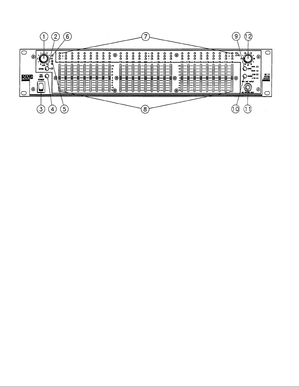
1. EQ LEVEL CONTROL: This controls level through the equalizer section and provides up to 6 dB overall gain. Turn
this control down if the overload LED lights up.
2. BYPASS SWITCH: Engage to BYPASS all equalizer sections. The Bypass LED lights whenever the BYPASS switch
is engaged.
3. POWER SWITCH: You’ve probably figured this one out by now...
4. PINK NOISE SWITCH: Engage to activate the built-in pink noise generator.
OFF when not in use. This prevents possible noise bleed-through into the program material.
5. SIGNAL PRESENT INDICATOR: This green LED lights with any input above -20 dBu (.078 volts), even in the
Bypass mode.
6. OVERLOAD INDICATOR: This red LED lights whenever the equalizer signal level reaches 4 dB below clipping.
7. ANALYZER DISPLAY LEDs: Bach red LED lights up when response is too high in that band; green LEDs light
when response is within +3 dB or +l dB of the selected curve; yellow LEDs come on when response is too low.
8. EQUALIZER SLIDERS: Calibrated in 3 dB increments, these sliders provide +12 dB of boost and -15 dB of cut at each
of the IS0 frequency centers.
9. CURVE SELECT SWITCH: The NORMAL position yields a flat response when all LEDs are green. The HOUSE
CURVE changes the response of the display such that the EQ sliders between 400 Hz and 1.6 kHz must be attenuated 3 dB to
obtain green LED response. This reduction in midrange results in a warmer more desirable sound at lower sound pressure
levels.
10. WINDOW SELECT SWITCH: In the ±3 dB position, the green LED in each band lights when signals of that
frequency are within 3 dB above or below the Normal or House curve, whichever is selected. In the ±l dB mode, system
response must be within 1 dB above or below the selected curve to light the green LEDs.
11. MICROPHONE INPUT JACK: Plug only the Rane Microphone into this jack — the DC volt-
age supplied by this jack could be damaging to any other microphone. When the mic is plugged
in, the display responds to whatever the mic picks up; when the mic is unplugged,
display to monitor the output of the equalizer section.
NOTE: Switch the pink noise generator
the jack automatically switches the
12. RTA LEVEL CONTROL: Use this knob to adjust the microphone level (or line level when the microphone is
unplugged) to properly drive the display. This control is accurately calibrated in dB-SPL; any display band whose LED is
green has the sound pressure level indicated by this knob (only with the mic plugged in).
2
Page 3
REAR PANEL DESCRIPTION
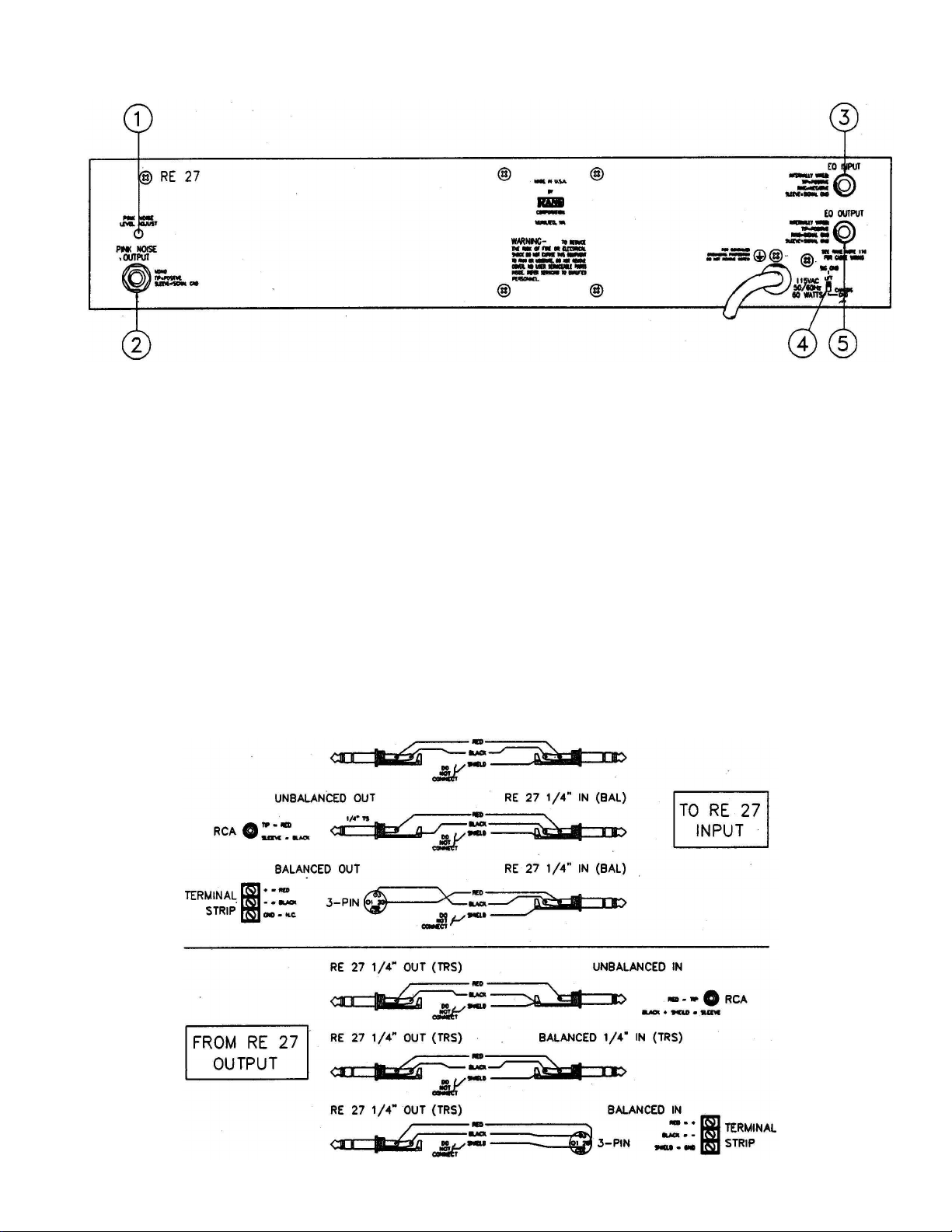
1. PINK NOISE LEVEL ADJUST: Use a 1/8" screwdriver to adjust the output from the Pink Noise generator from 0 to
1.2 volts (-4 dBu) to match the input level requirements of the mixer or other equipment.
2. PINK NOISE OUTPUT JACK: This is an unbalanced ¼" jack which supplies pink noise to the sound system.
3. EQ INPUT JACK: This is an automatic balanced unbalanced ¼" input to the equalizer section. Use a mono ¼" plug
for unbalanced operation, or a stereo TRS ¼" plug wired as shown in the diagram below for balanced operation
4. GROUND LIFT SWITCH: This switch provides the ability to separate chassis ground and signal ground. Normally,
this switch should be in the LIFT position. If you are tempted to try moving this switch with your power amplifiers turned
up,
don't be. Always turn your amplifier levels down before changing your grounds around and then bring them up slowly.
5. EQ OUTPUT JACK: This is the automatic unbalanced/quasi-floating output from the equalizer section. Use a mono
¼" plug for unbalanced operation or a stereo TRS ¼" plug wired as shown in the diagram below for use with balanced
equipment (Refer to RaneNote 102 for further information on Rane’s floating output system).
3
Page 4

3. PINK NOISE RUN-UP:
detonate your speaker cabinets. Now switch the PINK NOISE button IN on the RE 27 and turn up the mixer and EQ LEVEL
controls slowly until you hear pink noise through the speaker(s). There is a Pink Noise Output Level Adjustment on the rear
of the RE 27 - use a 1/8" screwdriver to vary the amount of pink noise to the mixer if necessary.
Turn down the mixer output controls before switching on the Pink Noise, so that you don’t
4. MICROPHONE PLACEMENT:
locations
a couple of different areas with the mic to obtain an average for the entire listening area. If you are using one equalizer
channel for both speakers (mono), place the mic in the center of the left half of the listening area and adjust for green LEDs
with pink noise through the left speaker. Now move the mic to the center of the right half of the listening area, run pink
noise through the right speaker and observe the analyzer LEDs: use the RTA LEVEL control to center the response for as
many green LEDs lit as possible. For each frequency that requires a different adjustment than the left channel, note the
original setting of the slider, then adjust it so that the green LED above it is lit and then note this new slider position: the
final setting should be half-way between these two slider positions, resulting in an average response for the left and right
channels. If you are running stereo, use two mic locations for each channel, averaging in the same manner if there are
differences.
izer. Drivers are aligned when maximum level is shown at the crossover frequency on the RE 27 display. It is important to
align drivers either physically or electronically in multi-way systems for the best sound. The mic should be at listener-ear
height relative to the center of the driver stack If a clear sound is desired in the back of the hall, the height of the RE 27 mic
should be in line with the on-axis phase response of the speaker stack, perpendicular to the drivers as shown below.
used for large concert halls, large theaters and outdoor facilities. Use the HOUSE CURVE for smaller concert halls, lounges,
churches, etc. In this mode the analyzer is modified requiring that all sliders between 400 Hz and 1.6 kHz must be attenuated
-3 dB in order to obtain green LED response (this is most easily seen in the ±l dB mode). This results in a warmer sound
quality at lower sound pressure levels, requiring less additional adjustment after the pink noise test.
switching to the ±1 dB mode for fine-tuning frequencies above 400 or 500 Hz. The crest factor (peak response) of true pink
noise causes considerable LED flutter in the ±1 dB mode below about 500 Hz, thus it is more expedient to use the ±3 dB
setting for these frequencies.
for each separate channel of EQ. Since speaker dispersion characteristics can vary greatly, it is desirable to look at
An RE 27 can be used as a driver alignment tool (see the AC 22/23 Owners Manual) as well as a room-flattening equal-
5. ANALYZER SETTINGS:
Now select either the ±3 dB or the ±l dB WINDOW on the analyzer. We recommend starting with the ±3 dB setting, then
Select either NORMAL or HOUSE CURVE on the RE 27 display. NORMAL is generally
You should perform the pink noise test
with
at least
two different test microphone
6. INITIAL SYSTEM ALIGNMENT:
ment in the system (EQ should always be a last resort after you’ve corrected response problems everywhere else). With all
EQ sliders flat (centered) adjust the electronic crossover frequencies and level controls (if used), passive crossover controls,
speaker placement and alignment, etc. to get as many green LEDs lit as possible on the display. Only after this is done
should you use the equalizer sliders to flatten the system (see next step).
7. EQUALIZER SLIDER ADJUSTMENTS: Now
above it is lit; if the red is lit, move the slider down until green comes on. If yellow is lit, move the slider up to obtain green
If you can’t get one or more green LEDs lit with their sliders fully boosted or cut, make a slight adjustment in the pink
noise volume or RTA LEVEL control to get these bands in the green. Then re-adjust the remaining sliders. You will also
notice that adjusting one slider may affect the LED readings on the adjacent bands: this is due to the presence of frequencies
half-way between the two bands, which will be affected by both sliders. Not to worry: simply nudge the adjacent slider until
the green LED lights up again.
Before using the equalizer for adjustment, use the analyzer to align other equip-
adjust each slider up or down as necessary until the green LED
4
Page 5

8. FINAL EQUALIZER ADJUSTMENTS:
alignment test. Now the speakers are properly coupled to the specific room and the overall system response is accurately
aligned. This alone will make a great improvement in most systems, but
has given you a consistent starting point, feel free to make further slider adjustments during the performance or sound check
to enhance overall sound quality. Fatten the bass, smoothen the mids or sweeten the highs to taste. You will probably find
that these adjustments will be consistently set above or below the pink noise test settings the same amount at each performance; make a note of these further adjustments to save future tweaking during performances. For example, you note the
pink noise settings and find later that you like to have 3 dB more boost at 63 Hz for more low-end punch during the performance. Next time, green out the analyzer during the pink noise test (get all LEDs green before making any further adjustment), then immediately bump up the 63 Hz slider 3 dB as indicated by the front panel calibrations so that you’re tuned up
before the show starts (slick, no?). The constant-Q sliders will assure accurate adjustments from any slider position.
Once the RE 27 is all “greened out”, you’re done with the pink noise
don’t stop at flat
necessarily. Now that the RE 27
9. USING THE RANE ANALYZER WITH OTHER EQUALIZER CHANNELS:
will respond to whatever program the test microphone picks up. Therefore, the display can be used to adjust any equalizer
channel which controls the pink noise through the speaker(s). Simply run pink noise through the desired equalizer and use
the analyzer/microphone combination to adjust that equalizer.
10. MONITORING PROGRAM MATERIAL FOR FEEDBACK USING THE DISPLAY:
completed, switch off the Pink Noise on the RE 27 and unplug the Rane test microphone from the front panel jack. When the
mic is unplugged, the display is automatically switched to monitor the output of the equalizer section. Adjust the RTA
LEVEL control so that an occasional green LED blinks on during the performance peaks, but no red LEDs come on: you
should be in the ±3 dB mode on the display. If feedback occurs, one or more red LEDs will light showing the genera1 feed-
back frequency area. Usually several red LEDs will be lit by the time you quickly cut back volume to kill the feedback and
glance at the display. When this happens keep watching the display: the last red LED to go off contains the exact feedback
frequency (it was the first LED on, too, but you probably didn’t see it). Adjust that slider down a couple dB and feedback
problem will be reduced. If you’re real good you’ll keep one eye on the analyzer display and quickly adjust one or two
sliders when feedback occurs, without altering master volume levels. This program monitoring feature is particularly useful
for stage monitors which are usually plagued with feedback problems.
TESTING:
The RE 27 really contains its own test equipment. By patching the PINK NOISE OUTPUT to the EQ INPUT with a mono
¼" patch cord (and no mike plugged in) the entire analyzer/equalizer/pink noise system can be checked and verified. Turn up
the RTA and EQ LEVEL controls until the display LEDs respond. With all sliders centered, the display should show all
green in the ±3 dB position with proper level settings. Switching to ±l dB should show mostly green with some LED flutter in
the lower frequency bands below 1 kHz (due to inherent crest factor of pink noise showing through the 2 dB window). Moving
each slider up and down should produce red and yellow LED response in that band. Switching to HOUSE CURVE should
cause red LEDs to light between approximately the 250 Hz and the 2.5 kHz bands.
The analyzer section of the RE 27
Once the pink noise test is
CHASSIS GROUNDING
Rane commercial equalizers are supplied with a rear mounted ground-lift switch. The unit is shipped with this switch
in the “grounded” position, tying circuit ground to chassis ground If after hooking up your system it exhibits excessive
hum or buzzing, there is an incompatibility in the grounding configuration between units somewhere. Your mission,
should you accept it, is to discover how your particular system wants to be grounded. Here are some things to try:
1. Try combinations of lifting grounds on units that are supplied with ground lift switches or links.
2. If your equipment is in a rack, verify that all chassis are tied to a good earth ground, either through the line cord
grounding pin or the rack screws to another grounded chassis.
3. Units with outboard power supplies do NOT ground the chassis through the line cord. Make sure that these units
are grounded either to another chassis which is earth grounded, or directly to the grounding screw on an AC outlet cover
by means of a wire connected to a screw on the chassis with a star washer to guarantee proper contact.
Please refer to RaneNote 110 (supplied with your unit and available on request at no charge if you lose it) for further
information on system grounding.
Page 6

INSTALLATION
This section contains several diagrams which shows many, but by no means all, of the ways to connect the RE 27 into a
sound reinforcement or monitor system. Whatever your particular application, it is helpful to realize that the RE 27 is
actually two independent products in one: an equalizer with input(s) and output(s), and a realtime analyzer with a mic input
and pink noise output.
MAIN SPEAKER EQUALIZATION
IMPORTANTNOTES:
1. See page 3 or Rane Note 110 for connector wiring.
2. To drive both left and right amplifier channels from a single RE 27 Output, use a “Y” connector to split the RE 27
Output to both left and right inputs of the amp or crossover.
series crossover , you need only connect the single RE 27 Output to the Channel 2 input of the crossover - both left and
right outputs will automatically be driven internally to eliminate the need for a “Y” connector.)
(NOTE: If you have the good fortune to be using a Rane AC
Page 7

STAGE MONITOR EQUALIZATION
IMPORTANT NOTES:
1. This set-up, using the Rane microphone, provides the most expedient method to optimize stage monitor sound quality
and reduce feedback problems. Feedback induced by specific stage mic/monitor speaker coupling can also be attenuated by
leaving the stage mic turned up and running up the pink noise level through the monitor speaker until feedback occurs.
Attenuate each feedback frequency, as indicated by the analyzer display, until the mic/monitor combination feeds back at
two or more frequencies simultaneously. Usually the final EQ setting will be a compromise between a good monitor sound
that doesn’t get as loud, or a not-so-good monitor sound that gets louder before feedback,
2. The run between the RE 27 and the monitor amp should be balanced whenever possible.
3. Place the Rane microphone at eye level of the performer and about six inches off to one side of the stage microphone,
in line of sight to the monitor speaker. If the stage microphone is directly between the Rane mic and monitor speaker
(blocking line of sight), some high frequencies will be blocked giving a false reading on the analyzer display.
4. If you are running more than one monitor from a single equalizer, test each monitor location by running up pink noise
until feedback occurs. The monitor which feeds back soonest should be used for the overall EQ adjustments using pink noise.
5. If maximum SPL before feedback is most important, use the stage mic only. If your mixer has a send/receive loop for
each input, temporarily patch the send from the stage mic mixer input to the RE 27 EQ INPUT, and patch the PINK NOISE
OUTPUT from the RE 27 to the receive. This arrangement allows the analyzer to look at the specific relationship between
each stage microphone/speaker combination. Since both the microphone and stage monitor speaker exhibit their own
individual feedback tendencies, the interaction between the two can cause pronounced feedback problems. This configuration allows you to flatten or “normalize” this interaction without actually getting to feedback levels. It should be noted that
this testing procedure favors maximum SPL before feedback and not necessarily optimum monitor sound quality. After the
equalizer curve is set, reconnect the system as shown above (without the Pink Noise connection). This configuration can also
be used for main speaker equalization to optimize system response for a specific microphone used throughout the system,
such as for choir, orchestral or big band situations where all program material is picked up through microphones of the same
make and model. After setting the equalizer curve, make the final output connection for the equalizer to the main amp(s) and
speakers instead of the monitor system as shown
6. Do not attempt to plug a regular microphone directly into the RTA MIC INPUT. See RaneNote 104 regarding use of
other microphones with the RE 27.
Page 8

RISK OF ELECTRIC SHOCK
DO NOT OPEN
CAUTION
IMPORTANT SAFETY INSTRUCTIONS
1. Read these instructions.
2. Keep these instructions.
3. Heed all warnings.
4. Follow all instructions.
5. Do not use this apparatus near water.
6. Clean only with a dry cloth.
7. Do not block any ventilation openings. Install in accordance with manufacturer’s instructions.
8. Do not install near any heat sources such as radiators, registers, stoves, or other apparatus (including ampliers) that produce heat.
9. Do not defeat the safety purpose of the polarized or grounding-type plug. A polarized plug has two blades with one wider than the other. A grounding-type plug has two blades and a third grounding prong. e wide blade or third prong is provided for your safety. If the provided plug does not
t into your outlet, consult an electrician for replacement of the obsolete outlet.
10. Protect the power cord and plug from being walked on or pinched particularly at plugs, convenience receptacles, and the point where it exits from
the apparatus.
11. Only use attachments and accessories specied by Rane.
12. Use only with the cart, stand, tripod, bracket, or table specied by the manufacturer, or sold with the apparatus. When a cart is used, use caution
when moving the cart/apparatus combination to avoid injury from tip-over.
13. Unplug this apparatus during lightning storms or when unused for long periods of time.
14. Refer all servicing to qualied service personnel. Servicing is required when the apparatus has been damaged in any way, such as power supply
cord or plug is damaged, liquid has been spilled or objects have fallen into the apparatus, the apparatus has been exposed to rain or moisture, does
not operate normally, or has been dropped.
15. e plug on the power cord is the AC mains disconnect device and must remain readily operable. To completely disconnect this apparatus from
the AC mains, disconnect the power supply cord plug from the AC receptacle.
16. is apparatus shall be connected to a mains socket outlet with a protective earthing connection.
17. When permanently connected, an all-pole mains switch with a contact separation of at least 3 mm in each pole shall be incorporated in the electrical installation of the building.
18. If rackmounting, provide adequate ventilation. Equipment may be located above or below this apparatus, but some equipment (like large power
ampliers) may cause an unacceptable amount of hum or may generate too much heat and degrade the performance of this apparatus.
19. is apparatus may be installed in an industry standard equipment rack. Use screws through all mounting holes to provide the best support.
WARNING: To reduce the risk of re or electric shock, do not expose this apparatus to rain or moisture. Apparatus shall not be exposed to dripping
or splashing and no objects lled with liquids, such as vases, shall be placed on the apparatus.
NOTE: is equipment has been tested and found to comply with the limits for a Class B digital device, pursuant to part 15 of the FCC Rules. ese
limits are designed to provide reasonable protection against harmful interference in a residential installation. is equipment generates, uses and can
radiate radio frequency energy and, if not installed and used in accordance with the instructions, may cause harmful interference to radio communications. However, there is no guarantee that interference will not occur in a particular installation. If this equipment does cause harmful interference to
radio or television reception, which can be determined by turning the equipment o and on, the user is encouraged to try to correct the interference
by one or more of the following measures:
• Reorient or relocate the receiving antenna.
• Increase the separation between the equipment and receiver.
• Connect the equipment into an outlet on a circuit dierent from that to which the receiver is connected.
• Consult the dealer or an experienced radio/TV technician for help.
CAU TIO N: Changes or modications not expressly approved by Rane Corporation could void the user's authority to operate the equipment.
is Class B digital apparatus complies with Canadian ICES-003.
Cet appareil numérique de la classe B est conforme à la norme NMB-003 du Canada.
WARNING
To reduce the risk of electrical shock, do not open the unit. No user
serviceable parts inside. Refer servicing to qualied service personnel.
e symbols shown below are internationally accepted symbols that warn
of potential hazards with electrical products.
is symbol indicates that a dangerous voltage
constituting a risk of electric shock is present within
this unit.
is symbol indicates that there are important
operating and maintenance instructions in the
literature accompanying this unit.
 Loading...