

Page 1

INSTALLATION MANUAL
NM 1
NETWORK MIC PREAMP
In Use / Conductor
Link / Activity
COBRANET
PRIMARY
COBRANET
SECONDARY
In Use / Conductor
Link / Activity
SWITCHES / LIGHTS
Connections
COBRANET PRIMARY Connector
COBRANET SECONDARY Connector
ese Neutrik Ethercon connectors accept CAT 5e Ethernet
cables terminated with the standard RJ-45 plug. ey are used
as the Primary and Secondary connections to a LAN carrying
CobraNet data. e Ethercon connectors also accept a Neutrikdesigned housing for RJ-45 plugs (Neutrik NE8MC series)
that is similar to the industry standard XLR connector. is
Ethercon plug is much more rugged than the standard RJ-45; a
version of the housing is available to retrot over CAT 5e cables
that are already terminated. (Note that certain cables such as
Belden MediaTwist require special strain-reliefs to work with the
Ethercon shell.)
e cabling used to connect the NM 1 to other Ethernet
equipment must be CAT 5e minimum. CAT 6 is also acceptable. For more information about CobraNet network design,
redundancy, and Primary and Secondary ports, please refer to
the CobraNet website www.cobranet.info.
Both the Primary and the Secondary ports fully support PoE
(IEEE 802.3af ). For the NM 1 to operate, at least one of the two
Ethernet ports must be connected to a device that is an IEEE
802.3af compliant Power Source Equipment (PSE). Power can
be supplied to the NM 1 through either the unused pairs of the
CAT 5 cable, or in a “phantom power” scheme using the data
pairs. is allows the use of PSE devices from manufacturers
that support either scheme. e NM 1 requests the maximum
power, approximately 13W, on both ports (see data sheet for
more details on power requirements). e PSE must be chosen
carefully to ensure that it can provide full power to every port
that is connected to a NM 1.
SPEAKER MIC INPUT
Power can be supplied to the NM 1 through either port; it
automatically switches between the ports to support fully redundant system designs. If power is available on both ports, the
NM 1 chooses one as the active power port. PoE supports equipment hot-plugging, so a PSE senses when a load is disconnected
and stops delivering power on that port. To allow the fastest possible switch-over from the active port, the stand-by port always
draws a minimum current from its PSE so the PSE is awake and
ready to deliver power as soon as the NM 1 needs it. is allows
seamless redundancy in the power supply to the NM 1.
Note the port the NM 1 chooses to power from is independent from the port that is being used for CobraNet data.
In Use / Conductor LEDs
ere is one yellow LED for each CobraNet port. is indicator lights on the port in use and blinks if the device is also the
Conductor. (More documentation is at www.cobranet.info)
Link / Activity LEDs
ere is one green LED for each CobraNet port. is indicator lights when Link is established and blinks when CobraNet
network activity is detected.
SWITCHES / LIGHTS Connector
is female DB-15 connector allows an external switch and lamp
panel to be attached for push-to-talk, cough mute, and other
similar functions. It is provided with lugs so that any DB-15 plug
with mounting ears and spring-latches can be used (e.g. Amp
part numbers for the spring latch are 745779-3 (bulk), 745779-2
(two/bag), 745255-3 (bulk) or 745255-2 (two/bag) )
Page 2
Switches / Lights Connector
(+)
Pinout
Pin 1 Talk button
Pin 2 Cough button
Pin 3 NC
Pin 4 Override button
Pin 5 Private button
Pin 6 Ground
Pin 7 Ground
Pin 8 Ground
Pin 9 Ground
Pin 10 Ground
Pin 11 Talk LED
Pin 12 Cough LED
Pin 13 NC
Pin 14 Override LED
Pin 15 Private LED
e LED output pins provide +12 VDC through 160Ω current limiting resistors when they are turned on. When turned o,
they are oating. LED indicators should be connected between
these pins and ground pins on this connector.
e switch inputs have internal pull-ups to +3.3 VDC and
are ESD protected. When a pushbutton input is needed, normally-open switches should be connected between one of these
inputs and a ground pin.
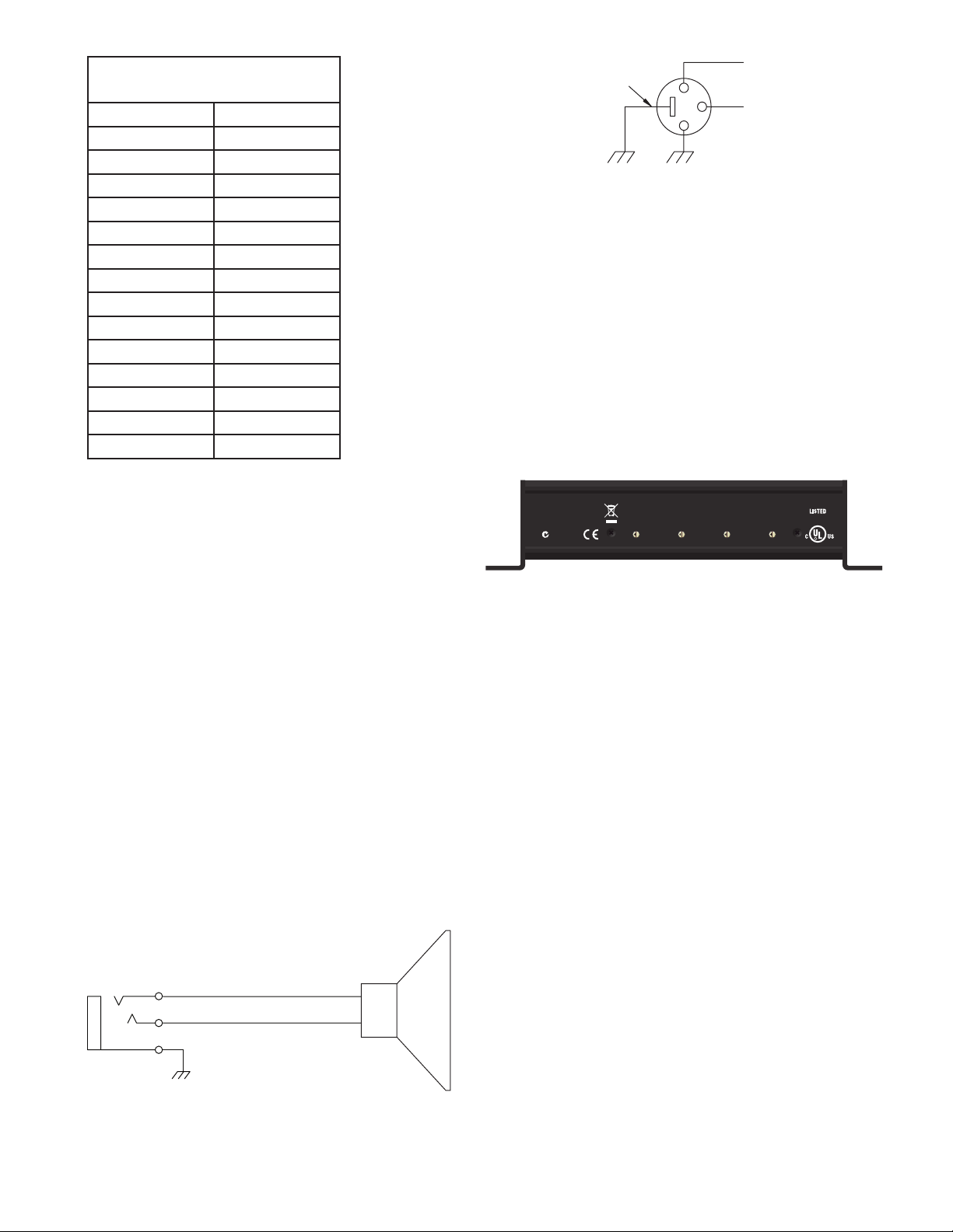
SPEAKER Connector
is amplier output is a standard ¼" TRS phone connector. It
is used to connect a 4Ω minimum loudspeaker to the NM 1 for
monitoring the selected CobraNet audio channel. e NM 1
power amplier can deliver 1 watt continuously into an 8Ω load
with a pink noise signal that has a 15 dB crest factor (see data
sheet for detailed specications). e output conguration requires that the positive and negative signals must remain isolated
from the chassis and from ground. e plug used mu st be TRS;
use of a TS (i.e. mono) phone plug shorts the power amplier
and causes a malfunction.
e threaded metal bushing allows use of a ¼" phone plug
with a threaded locking ring (e.g., Switchcraft Number 298).
e connector sleeve is connected directly to chassis ground;
the tip is the positive signal; the ring is the negative signal.
CASE
OPTIONAL
2
3
(–)
1
Figure 2. Mic wiring
MIC INPUT Connector
e balanced microphone input is an industry standard XLR-3
type connector (see the NM 1 Data Sheet for specications).
Gain is adjusted via SNMP control. IEC 61938 P48 compliant
48V phantom power is provided.
Connect pins 2 and 3 to the balanced output of the microphone. Pin 1 is directly connected to the chassis; for best noise
immunity, the microphone cable should have a braid or double
wound shield. If a cable such as Belden 1800F is used that has
both a wire shield and a drain wire, then all the shield wires and
not just the drain wire should be connected to pin 1 of the XLR
connector.
NM 1
Rane Corp.
Made in U.S.A.
ACN 001
345 482
1 2 3
5
4
3
6
7
2
1
9
0
F
A
E
B
D
C
SysName Switches
On the rear panel are four rotary switches that are used to create
a four digit identier that becomes part of the SNMP variable,
sysName. sysName is then used to uniquely identify a CobraNet
device on the network. e condition of being unique requires
that each device on the network have a dierent setting. Looking
at the unit with the switches facing you, as in the above diagram,
the identier reads from left to right.
us, setting the switches to 1, A, 3, 7, respectively, sets the
sysname variable to “NM1-Sw1A37.”
Mounting
e NM 1 is equipped with mounting ears to solidly attach it to
a surface if needed. Rubber feet are also included for tabletops.
SNMP
If you are new to SNMP or would like an easy overview, see the
RaneNote "SNMP: Simple? Network Management Protocol at
www.rane.com/note161.html.
SysName
5
4
3
2
8
1
0
F
E
D
5
4
3
6
6
7
7
2
8
8
1
9
9
0
F
A
A
E
B
B
D
C
C
2
1
0
F
4
4
3
E
D
5
6
7
8
9
A
B
C
COMMERCIAL AUDIO
EQUIPMENT 24TJ
R
–
+
Figure 1. Speaker wiring
Page 3

Appendix 1. Switches / Lights Connector Logic
Q
1
2
3
1
2
3
Cough
Button
Talk
Button
Override
Button
Privacy
Button
*Ground pins on the DB-15
connector are 6, 7, 8, 9, &10.
Pins 3 & 13 on the DB-15
connector are no-connects.
See the MIB for
explanation of variables.
*
*
*
* *
*
*
*
Pin 2 Pin 12
Pin 11
Pin 14
Pin 15
Pin 1
Pin 4
Pin 5
Internal pull-up,
debounce and
ESD protection.
Internal pull-up,
debounce and
ESD protection.
Internal pull-up,
debounce and
ESD protection.
Internal pull-up,
debounce and
ESD protection.
SNMP: talkToggle (read-write)
SNMP: talk
(read)
SNMP: override (read-only)
SNMP: privateMode (read)
SNMP: cough (read-only)
SNMP: microphoneMute
(read-only)
Flip-Flop
Toggle
Toggle
Q
Flip-Flop
Toggle
Toggle
SNMP: coughDisable (read-write)
SNMP: overrideDisable
(read-write)
SNMP: talk (write)
0 = clear ip-op
1 = set ip-op
“edge-triggered”
SNMP: privateMode (write)
0 = clear ip-op
1 = set ip-op
“edge-triggered”
SNMP: privateModeToggle (read-write)
Appendix 2. NM 1 MIB
--
-- RANE-NM1-MIB-V1.my
-- MIB generated by MG-SOFT Visual MIB Builder Version 4.0 Build 341
-- Thursday, May 20, 2004 at 17:53:02
--
RANE-NM1-MIB-V1 DEFINITIONS ::= BEGIN
IMPORTS
mfgExtensions
FROM PEAKAUDIO-MIB
OBJECT-TYPE
FROM RFC-1212
Counter
FROM RFC1155-SMI;
--
-- Node denitions
--
-- Node denitions
--
-- 1.3.6.1.4.1.2680.1.2.7
rane OBJECT IDENTIFIER ::= { mfgExtensions 7 }
-- 1.3.6.1.4.1.2680.1.2.7.3
NM1 OBJECT IDENTIFIER ::= { rane 3 }
-- 1.3.6.1.4.1.2680.1.2.7.3.1
micPreampGain OBJECT-TYPE
SYNTAX INTEGER (10..65)
ACCESS read-write
STATUS mandatory
DESCRIPTION
"Gain through the mic pre-
amplier stage. Gain can be
adjusted in 1 db increments
in the range 10dB through
65dB."
DEFVAL { 10 }
::= { NM1 1 }
-- 1.3.6.1.4.1.2680.1.2.7.3.2
microphoneMute OBJECT-TYPE
SYNTAX INTEGER
ACCESS read-only
STATUS mandatory
DESCRIPTION
"State of the microphone
mute.
0 - unmuted
1 - muted"
::= { NM1 2 }
Page 4

-- 1.3.6.1.4.1.2680.1.2.7.3.3
talk OBJECT-TYPE
SYNTAX INTEGER
ACCESS read-write
STATUS mandatory
DESCRIPTION
"Present state of the talk
button ip op.
0 - o
1 - on"
::= { NM1 3 }
-- 1.3.6.1.4.1.2680.1.2.7.3.7
override OBJECT-TYPE
SYNTAX INTEGER
ACCESS read-only
STATUS mandatory
DESCRIPTION
"Present state of the override
momemtary button.
0 - not depressed
1 - depressed"
::= { NM1 7 }
-- 1.3.6.1.4.1.2680.1.2.7.3.4
talkToggle OBJECT-TYPE
SYNTAX Counter
ACCESS read-write
STATUS mandatory
DESCRIPTION
"Toggle the talk button ip
op. Set this variable to any
value other than its current
value to cause the ip op to
change state."
::= { NM1 4 }
-- 1.3.6.1.4.1.2680.1.2.7.3.5
cough OBJECT-TYPE
SYNTAX INTEGER
ACCESS read-only
STATUS mandatory
DESCRIPTION
"Present state of the cough
momentary button.
0 - not depressed
1 - depressed"
::= { NM1 5 }
-- 1.3.6.1.4.1.2680.1.2.7.3.6
coughDisable OBJECT-TYPE
SYNTAX INTEGER
ACCESS read-write
STATUS mandatory
DESCRIPTION
"Control for disabling cough
button from the audio
muting logic. Cough
indicator will continue to
function normally but audio
will not be aected.
0 - cough function enabled
- default
1 - cough function disabled"
::= { NM1 6 }
-- 1.3.6.1.4.1.2680.1.2.7.3.8
overrideDisable OBJECT-TYPE
SYNTAX INTEGER
ACCESS read-write
STATUS mandatory
DESCRIPTION
"Control for disabling
override button from the
audio muting logic. Override
indicator will continue to
function normally but audio
will not be aected.
0 - override function enabled
- default
1 - override function disabled"
::= { NM1 8 }
-- 1.3.6.1.4.1.2680.1.2.7.3.9
privateMode OBJECT-TYPE
SYNTAX INTEGER
ACCESS read-write
STATUS mandatory
DESCRIPTION
"Present state of the private
mode button ip op.
0 - o
1 - on"
::= { NM1 9 }
-- 1.3.6.1.4.1.2680.1.2.7.3.10
privateModeToggle OBJECT-TYPE
SYNTAX Counter
ACCESS read-write
STATUS mandatory
DESCRIPTION
"Toggle the private mode
button ip op. Set this
variable to any value other
than its current value to
cause the ip op to change
state."
::= { NM1 10 }
END
--
-- RANE-NM1-MIB-V1.my
--
©Ran e Corp oration 108 02 47th Ave. W., Mukilte o WA 98275-509 8 TEL 425-355 -600 0 FAX 42 5-347-7757 WEB w ww.ra ne.com
All features & specications subject to change without notice 108422
 Loading...