

Page 1

OPERATORS MANUAL
MQ 302
STEREO GRAPHIC EQUALIZER
QUICK START
If this is your first equalizer, please do yourself and your speakers a favor and read at least the first five pages. “An
ounce of prevention...,” and all that.
The MQ 302 is a stereo equalizer, so adjusting any slider affects both Channels simultaneously. Begin by setting all
sliders to their center detent (0 dB), and the INPUT LEVEL to 8. Try to make more cuts than boosts. After equalizing, use
the EQ switch to compare equalized and non-equalized signal. While EQ is switched to ACTIVE (out), adjust the INPUT
LEVEL to the same level as when EQ is switched to BYPASS (in).
You may use either the XLR or ¼" connectors for Inputs or Outputs. Connect only one INPUT type per channel. The
XLR and ¼" TRS inputs do not sum. You may, however, use both types of OUTPUTS simultanesously if desired.
Manual-1
Page 2
RISK OF ELECTRIC SHOCK
DO NOT OPEN
CAUTION
IMPORTANT SAFETY INSTRUCTIONS
1. Read these instructions.
2. Keep these instructions.
3. Heed all warnings.
4. Follow all instructions.
5. Do not use this apparatus near water.
6. Clean only with a dry cloth.
7. Do not block any ventilation openings. Install in accordance with manufacturer’s instructions.
8. Do not install near any heat sources such as radiators, registers, stoves, or other apparatus (including ampliers) that produce heat.
9. Do not defeat the safety purpose of the polarized or grounding-type plug. A polarized plug has two blades with one wider than the other. A grounding-type plug has two blades and a third grounding prong. e wide blade or third prong is provided for your safety. If the provided plug does not
t into your outlet, consult an electrician for replacement of the obsolete outlet.
10. Protect the power cord and plug from being walked on or pinched particularly at plugs, convenience receptacles, and the point where it exits from
the apparatus.
11. Only use attachments and accessories specied by Rane.
12. Use only with the cart, stand, tripod, bracket, or table specied by the manufacturer, or sold with the apparatus. When a cart is used, use caution
when moving the cart/apparatus combination to avoid injury from tip-over.
13. Unplug this apparatus during lightning storms or when unused for long periods of time.
14. Refer all servicing to qualied service personnel. Servicing is required when the apparatus has been damaged in any way, such as power supply
cord or plug is damaged, liquid has been spilled or objects have fallen into the apparatus, the apparatus has been exposed to rain or moisture, does
not operate normally, or has been dropped.
15. e plug on the power cord is the AC mains disconnect device and must remain readily operable. To completely disconnect this apparatus from
the AC mains, disconnect the power supply cord plug from the AC receptacle.
16. is apparatus shall be connected to a mains socket outlet with a protective earthing connection.
17. When permanently connected, an all-pole mains switch with a contact separation of at least 3 mm in each pole shall be incorporated in the electrical installation of the building.
18. If rackmounting, provide adequate ventilation. Equipment may be located above or below this apparatus, but some equipment (like large power
ampliers) may cause an unacceptable amount of hum or may generate too much heat and degrade the performance of this apparatus.
19. is apparatus may be installed in an industry standard equipment rack. Use screws through all mounting holes to provide the best support.
WARNING: To reduce the risk of re or electric shock, do not expose this apparatus to rain or moisture. Apparatus shall not be exposed to dripping
or splashing and no objects lled with liquids, such as vases, shall be placed on the apparatus.
NOTE: is equipment has been tested and found to comply with the limits for a Class B digital device, pursuant to part 15 of the FCC Rules. ese
limits are designed to provide reasonable protection against harmful interference in a residential installation. is equipment generates, uses and can
radiate radio frequency energy and, if not installed and used in accordance with the instructions, may cause harmful interference to radio communications. However, there is no guarantee that interference will not occur in a particular installation. If this equipment does cause harmful interference to
radio or television reception, which can be determined by turning the equipment o and on, the user is encouraged to try to correct the interference
by one or more of the following measures:
• Reorient or relocate the receiving antenna.
• Increase the separation between the equipment and receiver.
• Connect the equipment into an outlet on a circuit dierent from that to which the receiver is connected.
• Consult the dealer or an experienced radio/TV technician for help.
CAU TION: Changes or modications not expressly approved by Rane Corporation could void the user's authority to operate the equipment.
is Class B digital apparatus complies with Canadian ICES-003.
Cet appareil numérique de la classe B est conforme à la norme NMB-003 du Canada.
WARNING
To reduce the risk of electrical shock, do not open the unit. No user
serviceable parts inside. Refer servicing to qualied service personnel.
e symbols shown below are internationally accepted symbols that warn
of potential hazards with electrical products.
is symbol indicates that a dangerous voltage
constituting a risk of electric shock is present within
this unit.
is symbol indicates that there are important
operating and maintenance instructions in the
literature accompanying this unit.
Page 3
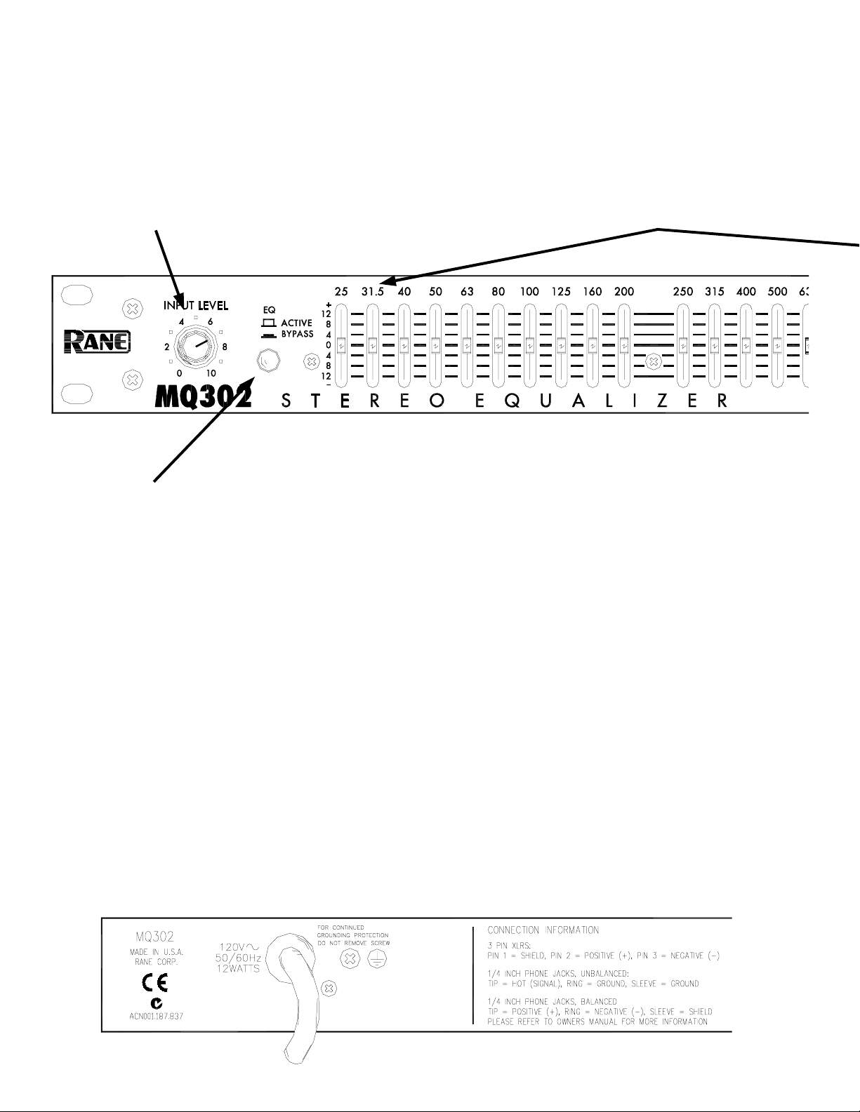
Filter level slide controls
INPUT LEVEL control
This controls the overall level. +6 dB gain is
reached at “10” with all sliders centered at
0 dB (see BYPASS switch below).
BYPASS switch
When pressed to BYPASS, the filter sliders
Each of these sliders controls the output
level of both Channels of the 30 bandpass
filters. Center position is grounded for
guaranteed flat response.
have no effect. Since actual unity gain
depends on varying slider settings, use the
BYPASS switch to determine the unity gain
position of the INPUT LEVEL control by
comparing ACTIVE and BYPASS volumes.
Cable Wiring
In agreement with IEC and AES/ANSI
standards, XLR wiring convention is pin 2
Positive (hot), pin 3 Negative (cold), and
pin 1 Signal ground (for unbalanced use).
Pin 1 and the connector case or shell are
tied to chassis ground.
Manual-2
Page 4
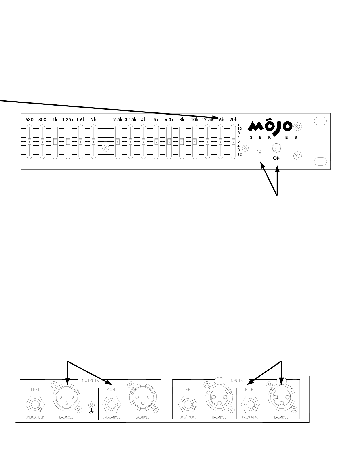
LEFT & RIGHT OUTPUTS
POWER switch and LED
Your basic, straightforward power switch.
When the yellow LED is lit, the MC 22 is
ready to go.
LEFT & RIGHT INPUTS
Choose between the balanced XLR or the
balanced/unbalanced ¼" TRS jacks, but
only use one. Inserting a ¼" TS jack will
Use either the Balanced XLR or the Unbal-
anced ¼" TS jacks. Using both types of
Outputs are permissible to drive two devices,
such as an amplifier and a recorder.
work—however—always use balanced lines
especially when connecting cables over 10
feet in length. Consult SOUND SYTEM
INTERCONNECTION on page Manual-8.
Manual-3
Page 5

MQ 302 CONNECTION
Exactly where you install your MQ 302 into a sound
system significantly affects such things as hum, noise, system
headroom, compressor/limiter performance and other factors
influencing overall sound quality. Both what and why you are
equalizing determines where you install it. We’ll leave the
when and who entirely up to you.
WHAT AND WHY
Since acoustic compensation and tone contouring are two
of the most common uses for equalization, here are a few
words on each.
ACOUSTIC COMPENSATION
Acoustic compensation is controlled nicely with a device
such as the MQ 302. The best way to “see” what room
acoustics are doing to your sound is to use a real time
analyzer. This test equipment lets you analyze the response of
the room and the sound system and is the only accurate means
available for setting an equalizer properly.
TONE CONTOURING
Contouring is accomplished mainly by ear. This you know
how to do. Be careful though, not to introduce too much boost
to the upper bass area (or the sub-bass area as in the last
warning). Be aware that the MQ 302 is capable of boosting
signals up to 12 dB (4 times as large!)—a level at which great
care should be taken to prevent seismic disturbances.
WHERE
For tone contouring, the equalizer may be used at any
point in the signal chain, such as insert loops in a mixer to
equalize a single instrument, sweeten a tape recording, etc.
When an equalizer is used for acoustical correction, the
equalizer should be one of the last pieces of gear in front of
the amplifiers and active crossovers. Any further up the line
may cause electrical mismatch with other line level equipment. Here are a few general guidelines useful in deciding
exactly where to install the MQ 302 in the system. See Figure
1.
AFTER ANY SYSTEM GAIN
Here is a trap many fall into: mixer, compressor/limiter,
equalizer, active crossover and power amplifier–all with gain
controls, and all working against each other. The MQ 302 has
good low noise levels, but it is a line-level active component.
If you set the INPUT LEVEL control way down (to avoid
overdriving the compressor which is wrongly connected after
it), then you must turn up the compressor, crossover and
amplifier controls to compensate; now you’ll blame the
equalizer for being too noisy. Whenever headroom allows,
try to take all the gain at the mixer, and run unity levels from
there on. This also gives better noise performance from the
mixer. Connect the MQ 302 before the amplifier or active
crossover. Take any required line gain before the MQ 302.
Avoid taking a lot of gain in the crossover or power amps as
this creates noise and hum problems. The MQ 302 operates at
unity gain around “8” on the INPUT LEVEL control when
sliders average to center (0 dB). You can test this with the EQ
BYPASS switch—adjust the INPUT LEVEL control so that
volume does not change when switching between ACTIVE
and BYPASS.
SEND/RECElVE LOOPS
Mixers, mixer/preamps and the like often provide send/
receive loops for additional effects or EQ, and the MQ 302
works well in this situation. Just be sure to keep input trim or
gain controls turned up as far as the mixer input headroom
will allow, to avoid taking excessive gain downstream and
creating noise problems. Remember to feed the MQ 302 with
roughly line level program (between -10 dBV and +4 dBu to
+20 dBu), and all should work fine.
DOWNSTREAM OF THE COMPRESSOR
Since system EQ is aimed at the acoustical problems, it
should be installed after any compressor, which is designed to
operate on electrical program material. For one thing, the
equalizer slider settings will change with each new location,
which in turn affects the control voltage and threshold
responses of the compressor and renders it inconsistent.
Secondly, healthy amounts of boost often strains the dynamic
range of compressors and increases the danger of distortion
and/or overload.
UPSTREAM OF THE LIMITER
If a limiter is installed strictly to protect the drivers, then
install the limiter just before the power amplifiers. A good
limiter leaves the dynamics unchanged until the amplifier
reaches driver overload levels.
Manual-4
Page 6

0;
67(5(2:$<&526629(5
04
67(5(2$03+,*+
5,*+7
/2:+,*+
/()7
67(5(2(48$/,=(5
0&
67(5(2&2035(6625
0$,12873876
0,;(5
Figure 1. Stereo Biamp System with Equalizer
OPERATING INSTRUCTIONS
The MQ 302 is an accurate, professional quality instrument capable of precise equalization down to a fraction of a
dB. You can expect several advantages from your constant-Q
equalizer over conventional designs: Moving one slider will
not affect neighboring filters as much, so you won’t spend
time re-adjusting sliders (we call this “equalizing the equalizer”). You’ll be able to obtain better feedback control
without losing sound quality. All sliders maintain smooth,
consistent and accurate calibrated control over filter levels,
which is especially critical in low-profile equalizer designs.
Because of this, the overall EQ adjustment process is significantly easier and more effective.
Equalizing a sound system by ear is a very difficult
process to achieve successfully, especially in a timely
manner. Although the human ear is very sensitive, it is not
calibrated, nor consistent, and frankly the odds against a well
behaved, clear sound system are very great when tuned by
ear. Most people know when a sound system doesn’t sound
good, unfortunately they just can’t tell exactly why and where
it’s not right. Because of this, we strongly recommend the
use of a realtime analyzer to properly equalizer your system
with the MQ 302.
Forget everything you’ve thought about analyzers and
consider this: there’s a newer generation of analyzers which
are compact, simple, very easy to operate and surprisingly
affordable. Best of all, they can make a drastic improvement
in the overall performance of your sound system while saving
/2:+,*+
67(5(2$03/2:
0212RU%5,'*('$03021268%
0212
68%:22)(5
you a great deal of time and effort.
A realtime analyzer helps you quickly achieve things
nearly impossible by ear: flatten speaker response, minimize
feedback, remove room resonance and allows accurate
crossover alignment. In most cases, simply “normalizing” or
“flattening” a sound system is a surprisingly drastic improvement, but don’t stop there:
Remember this Rane proverb: “Look, don’t stop, and
listen.” Once you have aligned the system by looking at the
analyzer, don’t stop at this point. Listen to the music
program and make additional adjustments to suit your taste,
the type of music and your audience. Fatten the bass, sweeten
the highs, brighten the mids. Since you are starting from a
“tuned” system, your ear will not be fooled into thinking bass
is too high when actually mids are too low, or that highs are
too weak when really the mids are too strong.
Fact: analyzers don’t have good taste—people do.
Analyzers consistently and accurately “tell it like it is,” but
ultimately, personal judgment determines what sounds good
or appropriate. In fact, final optimum EQ settings, made after
analyzer testing, will vary greatly depending on the type of
music, sound pressure level, size of the venue and disposition
of the audience.
Conclusion: To consistently obtain the best sound from
your system, use an analyzer and then your ears, in that
order. The analyzer supplies the consistency and calibration
while your ear supplies the good taste.
Manual-5
Page 7

MOJO GLOSSARY
balanced line The recommended method of interconnecting audio
equipment. A balanced line requires three conductors: a twisted-pair
for the signal (positive and negative) and an overall shield. The
shield must be tied to the chassis at both ends for hum-free interconnect.
bandwidth Abbr. BW The numerical difference between the upper
and lower -3 dB points of an audio band.
clipping What occurs when a unit tries to produce a signal larger
than its power supply. The signal takes on a flat-topped, or clipped
shape. When an amplifier tries to go above its max power, it clips.
compressor A signal processing device used to reduce the
dynamic range of the signal passing through it. For instance, an
input dynamic range of 110 dB might pass through a compressor and
exit with a new dynamic range of 70 dB. The modern usage for
compressors is to turn down (or reduce the dynamic range of) just
the loudest signals. Other applications use compressors to control the
creation of sound. When used in conjunction with microphones and
musical instrument pick-ups, compressors help determine the final
timbre by selectively compressing specific frequencies and waveforms.
connectors Audio equipment uses different styles:
RCA An unbalanced pin connector commonly used on
consumer and some pro equipment; aka phono plug
XLR A 3-pin connector common on pro audio equipment.
Preferred for balanced line interconnect; aka Cannon plug
¼" TRS 1. Stereo ¼" connector consisting of tip (T), ring (R),
and sleeve (S) sections, with T = left, R = right, and S =
ground/shield. 2. Balanced interconnect with the pos & neg
signal lines tied to T and R respectively and S acting only as an
overall shield. 3. Insert loop interconnect with T = send, R =
return, and S = ground/shield. [Think: ring, right, return]
¼" TS Mono ¼" connector consisting of tip (T) [signal] and
sleeve (S) [ground & shield] for unbalanced wiring.
constant-Q equalizer (also constant-bandwidth) The
bandwidth remains constant for all boost/cut levels. Since Q and
bandwidth are interrelated, the terms are fully interchangeable.
decibel Abbr. dB (named after Alexander Graham Bell). The
preferred method and term for representing the ratio of different
audio levels. Being a ratio, decibels have no units. Everything is
relative. So it must be relative to some 0 dB reference point. A suffix
letter is added to distinguish between reference points:
0 dBu A reference point equal to 0.775 V
+4 dBu Standard pro reference level equal to 1.23 V
0 dBV A reference point equal to 1.0 V
-10 dBV Standard reference level for consumer and some pro
audio use, equal to 0.316 V. RCA (phono) connectors are a
good indicator of units operating at -10 dBV
dynamic range The ratio of the loudest signal to the quietest
signal in a unit or system as expressed in decibels (dB).
expander A signal processing device used to increase the dynamic
range of the signal passing through it. Expanders complement
compressors. For example, a compressed input dynamic range of 70
dB might pass through a expander and exit with a new expanded
dynamic range of 110 dB. Modern expanders usually operate only
below a set threshold point, i.e., they operate only on low-level
audio. The term downward expander describes this type of applica-
tion.
ground Any electrical reference point for measuring voltage levels.
Usually a large conducting body, such as the earth or an electric
circuit connected to the earth. Chassis should always be at earth
potential.
WARNING: SHOCK HAZARD
Never use an AC line cord ground-lift adapter or cut
off the 3rd pin. It is illegal and dangerous.
headroom The level in dB between the typical operating level and
clipping. For example, a nominal +4 dBu system that clips at +20
dBu has 16 dB of headroom.
hum Unwanted sound contaminating audio paths due to EMI
(electro-magnetic interference) caused by AC power-lines &
transformers getting into unbalanced, poorly shielded, or improperly
grounded connecting cables. Hum has a definite smooth (sine wave)
repetitive sound based on the harmonics of 50/60 Hz such as 100/
120 Hz and 150/180 Hz.
interpolating Term meaning to insert between two points. If a
graphic equalizer’s adjacent bands, when moved together, produce
a smooth response without a dip in the center, they are interpolat-
ing between the fixed center frequencies.
levels Terms used to describe relative audio signal levels:
mic-level Nominal signal coming directly from a microphone.
Very low, in the microvolts, and requires a preamp with at least 60
dB gain before using with any line-level equipment.
line-level Standard +4 dBu or -10 dBV audio levels.
instrument-level Nominal signal from musical instruments
using electrical pick-ups. Varies widely, from very low mic-levels
to quite large line-levels.
limiter A compressor with a fixed ratio of 10:1 or greater. The
dynamic action prevents the audio signal from becoming larger than
the threshold setting.
Linkwitz-Riley crossover The most preferred active crossover
design. It features steep 24 dB/octave slopes, in-phase outputs, and
flat amplitude response. Due to the in-phase outputs the acoustic
lobe resulting when both loudspeakers reproduce the crossover
frequency is always on-axis (not tilted up or down) and has no
peaking.
noise 1. Interconnect. Unwanted sounds contaminating audio paths.
RFI (radio frequency interference) caused by broadcast signals
leaking into unbalanced, poorly shielded, or improperly grounded
connecting cables. Also by light dimmers, motor controls and
computers. 2. Music. A random mix of audio frequencies not
harmonically related, sounding like radio static.
polarity A signals electromechanical potential with respect to a
reference. For example, a microphone has positive polarity if a
positive pressure on its diaphragm results in a positive output
voltage. polarity vs. phase shift: polarity refers to a signals
reference NOT to its phase shift. Being 180 degrees out-of-phase and
having inverse polarity are DIFFERENT things. We wrongly say
something is out-of-phase when we mean it is inverted. One occurs
over a period of time; the other occurs instantaneously.
Q (upper-case) Quality factor. Defined to be the ratio of the center
frequency f divided by the bandwidth BW for a bandpass filter.
signal-to-noise ratio The ratio in dB between a reference level
and the noise floor. For example, a signal-to-noise ratio of 90 dB re
+4 dBu, means the noise floor is 90 dB below a +4 dBu ref.
unbalanced line An audio interconnect scheme using one wire
with an overall shield. The shield must perform two functions: act as
the return signal path (ground) and to protect the conductor from
noise (shield). Consequently this method is vulnerable to hum &
noise problems.
unity gain A gain setting of one. The level out equals the level in.
Manual-6
Page 8

MQ 302 SPECIFICATIONS
Parameter Specification Limit Units Conditions/Comments
Equalizer:
..........Channels Two
..........Bands (2x30) 1/3-Octave ISO Spacing From 25 Hz to 20 kHz
..........Type Constant-Q Smooth combining
..........Accuracy 3 % Center frequency
..........Travel 20 mm Positive grounded center detent
..........Range ±12 1 dB
Inputs:
..........Type Active Balanced
..........Connectors XLR & ¼" TRS Pin 2 “hot” per AES standards
..........Impedance 20k 1% ohms
..........Maximum Level 21 1 dBu
Outputs:
..........XLR Active Balanced 100 ohms impedance each leg
..........¼" Active Unbalanced 100 ohms impedance
..........Maximum Level +20 1 dBu 2k ohms balanced & unbalanced
Overall Gain Range Off to +6 -0/+4 dB Sliders centered
RFI Filters Yes
Frequency Response 20-20 kHz +0,-2 dB
THD+Noise 0.009 .002 % +4 dBu, 20-20 kHz
IM Distortion (SMPTE) 0.005 .003 % 60 Hz/7 kHz, 4:1, +4 dBu
Signal-to-Noise Ratio 20 kHz noise BW; balanced out re +4 dBu
96 2 dBr Sliders centered, re +4 dBu, 20 kHz BW
76 2 dBr Sliders all boosted, re + 4 dBu, 20 kHz BW
91 2 dBr Sliders all cut, re + 4 dBu, 20 kHz BW
Channel Separation 80 3 dB 1 kHz
Common Mode Rejection 40 1 dB 1 kHz
Maximum Power 12 W
Unit: Agency Listing
………120 VAC model UL UL 6500 (file E104174)
cUL (Canada) C22.2 (file E104174)
………230 VAC model CE (EMC) EN55013, EN55020 EMC Directive 89/336/EEC
CE (Safety) EN60065 LV Directive 73/23/EEC
..........Construction All Steel
..........Size 1.75"H x 19"W x 8.5"D (1U) (4.4 cm x 48.3 cm x 21.6 cm)
..........Weight 5 lb (2.3 kg)
Shipping:
..........Size 4.25" x 20.3" x 13.75" (11 cm x 52 cm x 35 cm)
..........Weight 9 lb (4.1 kg)
Note: 0 dBu = 0.775 Vrms
Manual-7
Page 9

SOUND SYSTEM
INTERCONNECTION
Rane’s policy is to accommodate rather than dictate.
However, this document contains suggestions for external
wiring changes that should ideally only be implemented by
trained technical personnel. Safety regulations require that all
original grounding means provided from the factory be left
intact for safe operation. No guarantee of responsibility for
incidental or consequential damages can be provided. (In
other words, don’t modify cables, or try your own version of
grounding unless you really understand exactly what type of
output and input you have to connect.)
THE ABSOLUTE BEST RIGHT WAY TO DO IT
Use balanced lines and tie the cable shield to the metal
chassis (right where it enters the chassis) at both ends of the
cable.
A balanced line requires three separate conductors, two of
which are signal (+ and –) and one shield. The shield serves
to guard the sensitive audio lines from interference. Only by
using balanced line interconnects can you guarantee (yes,
guarantee) hum-free results. Always use twisted pair cable.
Chassis tying the shield at each end also guarantees the best
possible protection from RFI [radio frequency interference]
and other noises [neon signs, lighting dimmers].
THE NEXT BEST RIGHT WAY TO DO IT
The quickest, quietest and most foolproof method to
connect balanced and unbalanced is to transformer isolate
all unbalanced connections. Your audio dealer can recommend such a transformer.
The goal of transformer adaptors is to allow the use of
standard cables. With these transformer isolation boxes,
modification of cable assemblies is unnecessary. Virtually
any two pieces of audio equipment can be successfully
interfaced without risk of unwanted hum and noise.
Another way to create the necessary isolation is to use a
direct box. Originally named for its use to convert the high
impedance, high level output of an electric guitar to the low
impedance, low level input of a recording console, it allowed
the player to plug “directly” into the console. Now this term is
commonly used to describe any box used to convert unbalanced lines to balanced lines.
THE LAST BEST RIGHT WAY TO DO IT
If transformer isolation is not an option, special cable
assemblies are a last resort. The key here is to prevent the
shield currents from flowing into a unit whose grounding
scheme creates ground loops (hum) in the audio path (i.e.,
most audio equipment). Do not be tempted to use 3-prong to
2-prong “cheater” adapters to lift grounds. This is a dangerous and illegal practice.
It is true that connecting both ends of the shield is theoretically the best way to interconnect equipment – though this
assumes the interconnected equipment is internally grounded
properly. Since most equipment is not internally grounded
properly, connecting both ends of the shield is not often
practiced, since doing so can create noisy interconnections.
A common solution to these noisy hum and buzz problems
involves disconnecting one end of the shield, even though one
can not buy off-the-shelf cables with the shield disconnected
at one end. The best end to disconnect is a matter of personal
preference and should be religiously obeyed; choose inputs or
outputs and always lift the side you choose (our drawings
happen to disconnect the outputs). If one end of the shield is
disconnected, the noisy hum current stops flowing and away
goes the hum — but only at low frequencies. A one-end-only
shield connection increases the possibility of high frequency
(radio) interference since the shield may act as an antenna.
Many reduce this potential RF interference by providing an
RF path through a small capacitor (0.1 or 0.01 microfarad
ceramic disc) connected from the lifted end of the shield to
the chassis. The fact that many modern day installers still
follow this one-end-only rule with consistent success indicates this and other acceptable solutions to RF issues exist,
though the increasing use of digital and wireless technology
greatly increases the possibility of future RF problems.
See the following page for suggested cable assemblies for
your particular interconnection needs. Find the appropriate
output configuration from either your mixer output or the MQ
302 output (down the left side), and then match this with the
correct balanced or unbalanced input to the MQ 302 or the
amplifer (down the right side.) An “off-the-shelf” cable may
be available or modifiable. Soldering should only be attempted by those trained in the art.
SUMMARY
If you are unable to do things correctly (i.e. use fully
balanced wiring with shields tied to the chassis at the point of
entry, or transformer isolate all unbalanced signals from
balanced signals) then there is no guarantee that a hum free
interconnect can be achieved, nor is there a definite scheme
that will assure noise free operation in all configurations.
WINNING THE WIRING WARS
• Use balanced connections whenever possible.
• Transformer isolate all unbalanced connections from
balanced connections.
• Use special cable assemblies when unbalanced lines cannot
be transformer isolated.
• Any unbalanced cable must be kept under ten feet (three
meters) in length. Lengths longer than this will amplify
the nasty side effects of unbalanced circuitry's ground
loops.
This information was condensed from Rane Note 110,
“Sound System Interconnection”. If you would like the
complete note, call or email the factory, download it from
Rane's web site (addresses on page Manual-10) , or ask your
dealer for a copy.
Manual-8
Page 10

VARIOUS XLR & ¼" CABLE ASSEMBLIES
Manual-9
Page 11

MQ 302 BLOCK DIAGRAM
©Rane Corporation 10802 47th Ave. W., Mukilteo WA 98275-5098 TEL (425)355-6000 FAX (425)347-7757 WEB http://www.rane.com
Manual-10
All features & specifications subject to change without notice. MAR98
 Loading...