

Page 1
OPERATORS MANUAL
SIG / OL
CUE
1
CUE
2
ENGAGE
SIG / OL
MIX LEVEL
4
INPUT GAIN
2
3
9
110
8
65
7
4
2
3
9
110
8
65
7
CUE PGM
POWER
STEREO
XP 2016S
MASTER
CUE
EFFECTS
LOOP
MONO
BOOTH
+6OFF
0 TREBLE
12
SIG / OL
MIX LEVEL
4
INPUT GAIN
2
3
9
110
8
AUX 5
AUX 4
AUX 3
65
AUX 2
AUX 1
AUX 5
AUX 4
AUX 3
PHONO /
LINE
PHONO /
LINE
PHONO /
LINE
PHONO /
LINE
MIC 1
ENGAGE
MIC 2
AUX 2
AUX 1
7
4
2
3
9
110
8
65
7
CUE
3
3
SIG / OL
MIX LEVEL
4
INPUT GAIN
2
3
9
110
8
AUX 5
AUX 4
AUX 3
65
AUX 2
AUX 1
7
4
2
3
9
110
8
65
7
CUE
4
4
SIG / OL
MIX LEVEL
4
INPUT GAIN
2
3
9
110
8
AUX 5
AUX 4
AUX 3
65
AUX 2
AUX 1
7
4
2
3
9
110
8
65
7
CUE
5
5
SIG / OL
MIX LEVEL
4
INPUT GAIN
2
3
9
110
8
AUX 5
AUX 4
AUX 3
65
AUX 2
AUX 1
7
4
2
3
9
110
8
65
7
CUE
6
6
SIG / OL
MIX LEVEL
4
INPUT GAIN
2
3
9
110
8
AUX 5
AUX 4
AUX 3
65
AUX 2
AUX 1
7
4
2
3
9
110
8
65
74
8
6
8
6
22
4
4
2
3
9
110
8
65
7
LEVELMONITOR PHONES
4
2
3
9
110
8
65
7
HOUSE
4
2
3
9
110
8
65
7
MASTER
MP 2016S
ROTARY
MIXER
+6OFF
0 MID
+6
OFF
0 BASS
STEREO
MONO
MP 2016S
ROTARY DJ MIXER
QUICK START
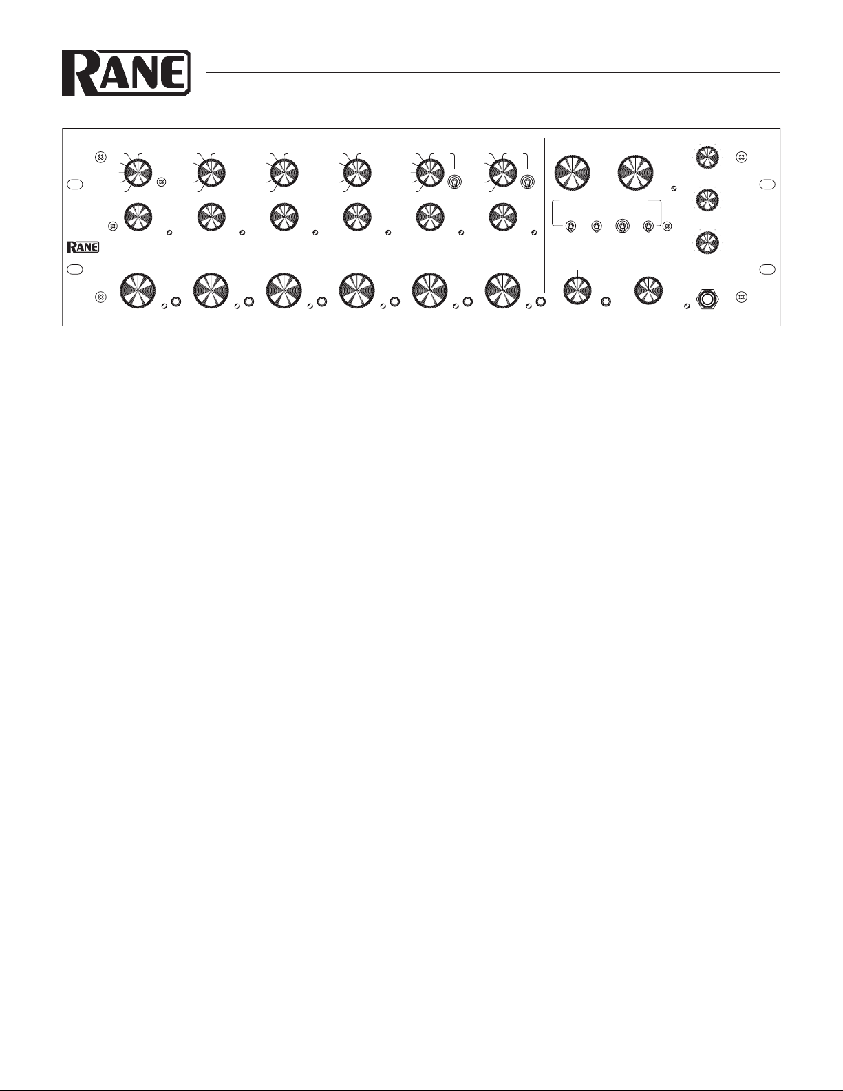
You asked for it, you got it! e MP 2016S now has Split Cue! If
you don’t know what that is, we suggest you take the time to
read this entire manual so you learn lots of other things to get
the best sound and features out of your new mixer. But if you
know what Split Cue is, at least read this section to refresh your
knowledge of the rest of the MP 2016S.
ere are four dedicated phono preamplifiers. One each for
Input channels 1-4. Switches on the rear panel set each preamplifier for LINE or PHONO operation. Make sure you have these
switches set correctly for your application.
ere are two dedicated MIC preamplifiers, one each for
Input channels 5-6. Rear panel switches set each preamplifier for
LINE or MIC operation. Make sure you have these switches set
correctly. MIC GAIN controls adjust each preamplifier for the
correct sensitivity. With a MIC selected and ENGAGED, set the
front INPUT GAIN control to “10” and adjust the rear MIC
GAIN to just keep the Input Channel SIG / OL indicator green,
not red. Set the rear panel tone controls as desired. e MIC
ENGAGE switch ducks the BOOTH Output by 12 dB unless
defeated with internal jumpers.
Before installing this mixer permanently, be sure to read the
MIC / LINE INPUTS section on page Manual-6.
All five stereo line-level AUX Inputs are available for each of
the six Input Channels.
Adjust the INPUT GAIN controls so they blink the green
SIG / OL indicators. If an indicator is red, the INPUT GAIN
control is set too high. is provides optimum signal to noise,
dynamic range and MIX LEVEL control consistency.
e BOOTH may select CUE or MASTER as its source.
CUE allows monitoring Inputs in the booth without headphones.
WEAR PART
e MP 2016S contains no wear parts. e XP 2016S contains the following wear part subject to the ninety (90) day warranty period
described on page Service-1: (1) Active Crossover Assembly F 60X.
e XP 2016S switch engages the optional XP 2016S proces-
sor. If the XP 2016S is not connected, the switch has no effect.
e EFFECTS LOOP switch switches the Loop in (up) or
out (down). If nothing is connected to the EFFECTS LOOP
RETURN, the switch has no effect.
e MASTER MONO / STEREO switch influences both
BOOTH and HOUSE OUTPUTS. It does not affect the EFFECTS LOOP or TAPE OUTPUTS.
Tw o TAPE OUTPUTS are provided. One is a PRE-EF-
FECTS Loop and one is a POST-EFFECTS Loop. e POSTEFFECTS Loop Tape Output has a LEVEL control and may be
used as a pre-tone control AUX Output.
e MP 2016S Master Output uses Accelerated Slope ™ tone
controls that provide full “kill” for TREBLE, MID and BASS.
e MASTER SIG / OL indicator monitors the master mix
before and after the tone controls. is indicator should light
green most of the time. It is OK for it to flash red on occasion.
is provides optimum signal-to-noise and dynamic range.
HOUSE and BOOTH are the only level controls that do not
affect the MASTER SIG / OL indicator.
e HOUSE OUTPUT has both balanced (XLR) and
unbalanced (RCA) Outputs. To avoid hum, always use the balanced (XLR) Outputs for longer cable runs (typically greater
than 10 feet, or 3 meters).
Headphone cueing allows monitoring MASTER or CUE
sources. If MIX LEVEL controls are operated at less than “7”, be
sure to turn the PHONES LEVEL down before selecting a CUE
as it may be much louder than the Master Mix. e Headphone
Output is low-impedance high-current, so do not short the tip
and ring together or to ground.
Manual-1
Page 2
MP 2016S FRONT PANEL CONTROLS
ENGAGE
12
AUX 5
AUX 4
AUX 3
AUX 2
AUX 1
AUX 5
AUX 4
AUX 3
PHONO /
LINE
PHONO /
LINE
PHONO /
LINE
PHONO /
LINE
MIC 1
ENGAGE
MIC 2
AUX 2
AUX 1
3
AUX 5
AUX 4
AUX 3
AUX 2
AUX 1
4
AUX 5
AUX 4
AUX 3
AUX 2
AUX 1
5
AUX 5
AUX 4
AUX 3
AUX 2
AUX 1
6
AUX 5
AUX 4
AUX 3
AUX 2
AUX 1
4
2
3
9
110
8
65
7
4
2
3
110
MASTER
SIG / OL
CUE
1
CUE
2
ENGAGE
MIX LEVEL
4
INPUT GAIN
2
3
9
110
8
65
7
4
2
3
9
110
8
65
7
CUE PGM
XP 2016S
MASTER
CUE
EFFECTS
LOOP
BOOTH
12
SIG / OL
MIX LEVEL
4
INPUT GAIN
2
3
9
110
8
AUX 5
AUX 4
AUX 3
65
AUX 2
AUX 1
AUX 5
AUX 4
AUX 3
PHONO /
LINE
PHONO /
LINE
PHONO /
LINE
PHONO /
LINE
MIC 1
ENGAGE
MIC 2
AUX 2
AUX 1
7
4
2
3
9
110
8
65
7
CUE
3
3
SIG / OL
MIX LEVEL
4
INPUT GAIN
2
3
9
110
8
AUX 5
AUX 4
AUX 3
65
AUX 2
AUX 1
7
4
2
3
9
110
8
65
7
CUE
4
4
SIG / OL
MIX LEVEL
4
INPUT GAIN
2
3
9
110
8
AUX 5
AUX 4
AUX 3
65
AUX 2
AUX 1
7
4
2
3
9
110
8
65
7
CUE
5
5
SIG / OL
MIX LEVEL
4
INPUT GAIN
2
3
9
110
8
AUX 5
AUX 4
AUX 3
65
AUX 2
AUX 1
7
4
2
3
9
110
8
65
7
CUE
6
6
SIG / OL
MIX LEVEL
4
INPUT GAIN
2
3
9
110
8
AUX 5
AUX 4
AUX 3
65
AUX 2
AUX 1
7
8
6
8
6
22
4
4
2
3
9
110
8
65
7
4
2
3
9
110
8
65
7
HOUSE
4
2
3
110
MASTER
STEREO
MONO
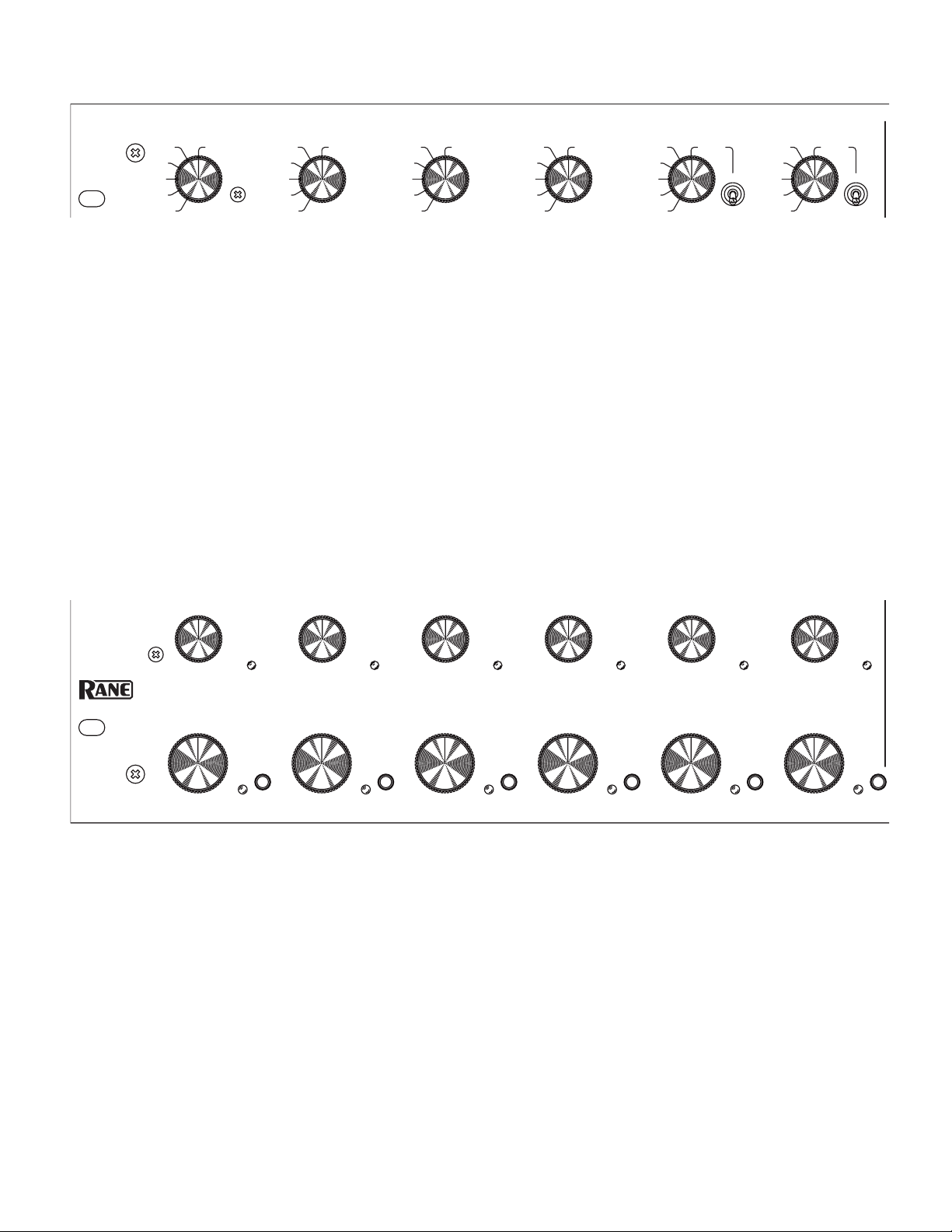
INPUT SELECTORS 1-4
Each six-position Input Selector chooses a dedicated PHONO /
LINE preamplifier, or one of five stereo line-level AUX Inputs as
its Input Channel source. (PHONO / LINE switches are on the
rear panel).
INPUT SELECTORS 5-6
Each six-position Input Selector chooses a dedicated mono MIC
Input, or one of five stereo AUX Inputs as its Input Channel
source. (MIC GAIN trim, MIC / LINE switch and MIC tone
controls are located on the rear panel).
MIC ENGAGE
MIC 1 and MIC 2 ENGAGE switches allow switching a mic on
(up) or off (down). A MIC Input must be selected and MIC EN-
GAGE on to activate a MIC Input. When a mic is not in use, be
sure to switch MIC ENGAGE off. e MIC ENGAGE switches
also activate the Booth Ducker. is attenuates the Booth Output -12 dB whenever a MIC ENGAGE switch is on, even if MIC
Input is not selected (internal jumpers allow disabling the Booth
Ducker—see Mic/Line Inputs on page Manual-6).
INPUT GAIN
INPUT GAIN controls allow the user to match input levels.
Adjust these to make the SIG / OL indicator flash green. If the
indicators turn red, reduce the INPUT GAIN. Adjusting the
INPUT LEVEL controls correctly maximizes dynamic range
and provides consistent MIX LEVEL response.
Input SIG / OL
ese dual-color indicators provide help in setting correct input
levels. A flashing green indication is optimal. A red light that
lasts more than a flash is a request to turn down the INPUT
GAIN.
Manual-2
MIX LEVEL
ese studio-grade controls determine the Master MIX LEVEL.
For optimum performance, set the INPUT GAIN controls as
indicated previously, and then operate MIX LEVELS between
“7” and “10” for full volume. Use the HOUSE and BOOTH
LEVEL controls to set the output levels. Always set the MIX
LEVEL controls to minimum when not in use.
CUE
e CUE signal is selected using CUE 1-6 switches in any
combination. e associated yellow indicator lights when a CUE
is active.
Page 3
HEADPHONE MONITOR
SIG / OL
CUE PGM
POWER
STEREO
XP 2016S
MASTER
CUE
EFFECTS
LOOP
MONO
BOOTH
+6OFF
0 TREBLE
4
2
3
9
110
8
65
74
8
6
8
6
22
4
LEVELMONITOR PHONES
4
2
3
9
110
8
65
7
HOUSE
4
2
3
9
110
8
65
7
MASTER
MP 2016S
ROTARY
MIXER
+6OFF
0 MID
+6
OFF
0 BASS
STEREO
MONO
T = LEFT
R = RIGHT
S = GROUND
TO MONO PHONE
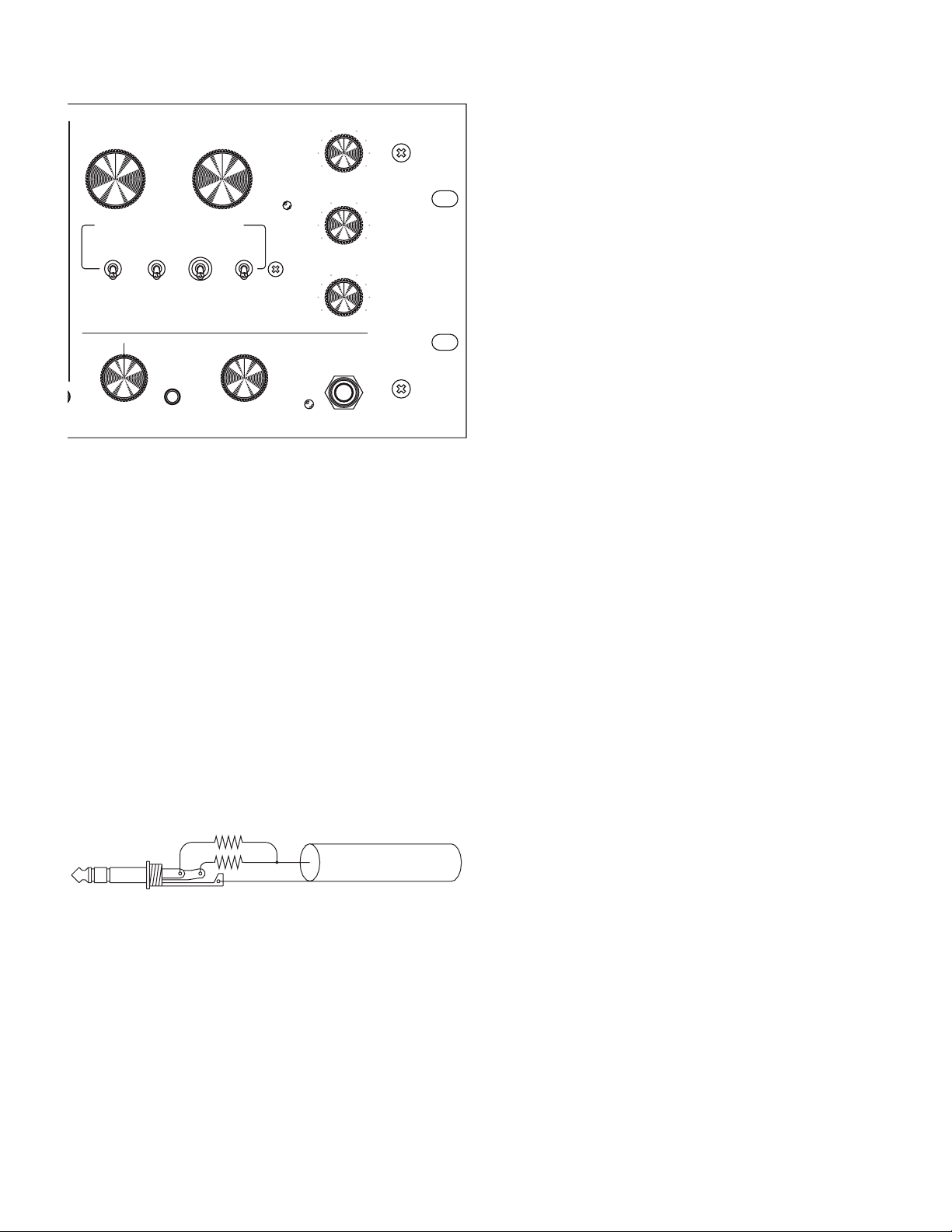
MONITOR determines the source of the PHONES signal. With
the MONITOR MONO switch out, the control pans between
stereo CUE and stereo PGM signals. e PGM signal follows
the HOUSE Output (same signal going to the Master House).
With MONITOR MONO selected (in), the MONITOR
control pans between mono CUE (left ear) and mono PGM
(right ear).
e Phones LEVEL control determines the headphone output level. If you are mixing with the MIX LEVEL controls below
“7”, be sure to turn the Phones LEVEL down before selecting a
CUE source as it may be much louder than the Master Mix.
e PHONES output is very low impedance and high
current so do not short tip and ring together or tie to ground, as
is common with many low- cost mono cups. Use resistors of
300 to 600 Ω in series with each output for mono applications,
although this significantly reduces output power.
BOOTH CUE / MASTER switch and Level
e BOOTH CUE / MASTER switch selects MASTER
mix or CUE selection as the Booth source. is allows CUE
monitoring in the Booth without headphones. e BOOTH
Level controls the volume to the Booth Output.
MASTER HOUSE Level
is studio-grade control sets the HOUSE Output level.
MASTER MONO / STEREO switch
is sets the MASTER mix signal to MONO or STEREO operation. It effects both BOOTH and HOUSE Outputs.
MASTER SIG / OL indicator
is dual color indicator helps set correct MASTER mix levels.
A flashing or steady green indication is optimal. e red indicator may flash only briefly on rare occasion...regular flashing or
steady-on means that distortion is imminent and Levels need
reducing.
XP 2016S switch
is engages the optional XP 2016S External Processor. If the
XP 2016S is not connected, the switch does nothing. If an XP
2016S is connected and the switch is on (up), it routes the MIX
LEVEL Outputs to the XP 2016S and returns a stereo MASTER
signal to the MP 2016S.
EFFECTS LOOP switch
is engages the EFFECTS LOOP when up. If nothing is connected to the EFFECTS LOOP RETURN, the switch has no
effect.
TREBLE tone control
Allows adjusting the amplitude of frequencies above 4 kHz from
+6 dB to OFF (full kill).
MID tone control
Allows adjusting the amplitude of frequencies between 300 Hz
and 4 kHz from +6 dB to OFF (full kill).
BASS tone control
Allows adjusting the amplitude of frequencies below
300 Hz from +6 dB to OFF (full kill).
POWER indicator
is yellow indicator lights whenever AC power is connected to
the unit.
Manual-3
Page 4

REAR PANEL INPUTS & OUTPUTS
MIC 2
MIC 1
4
INPUTS
321
GAIN
TREBLE
-12-12 +12
0
BASS
MIC
LINE
+12
0
+12-120-12 +12
0
GAIN
BASS TREBLE
—
PHONO GROUND
—
LINE
PHONO
R
L
R
L
R
L
R
L
MIC
LINE
XLR WIRING
PIN 2 = POSITIVE
PIN 3 = NEGATIVE
PIN 1 = CHASSIS GROUND
This device complies with Part 15 of the FCC Rules. Operation is
subject to the following two conditions: (1) this device may not cause
harmful interference, and (2) this device must accept any interference
received, including interference that may cause undesired operation.
MIC 1 and MIC 2 XLR jacks
e MIC 1 Input provides a dedicated balanced preamplifier
for Input Channel 5, while MIC 2 provides the preamplifier for
Input Channels 6. Each may operate in MIC or LINE mode.
Each of these preamplifiers features GAIN trim with BASS and
TREBLE tone controls.
MIC / LINE switches
ese select MIC or LINE mode for the MIC Inputs. In MIC
mode, the gain range is 20 to 50 dB. In LINE mode, the gain
range is 0 to 30 dB. In addition to setting the proper gain range
for MIC or LINE level Inputs, these switches also select the
proper Input impedance.
MIC GAIN trim
ese controls adjust the preamplifier for optimum dynamic
range. Each has a range of 30 dB, allowing a wide range of
sources to be used. To properly set this control, set the associated
front panel INPUT GAIN to “10”, turn the MIC ENGAGE
switch on and adjust the MIC GAIN so that the input SIG / OL
indicator flashes red only during very loud peaks. e front panel
INPUT GAIN control can then be adjusted as required according to the instruction outlined above under INPUT GAIN
control.
INPUTS 1-4 RCA jacks
INPUTS 1-4 provide dedicated preamplifiers for Input Channels
1-4 respectively. Each may operate in RIAA PHONO or LINE
mode.
PHONO / LINE switches
ese switches set Input Channel preamplifiers 1-4 for PHONO
or LINE mode. Make certain these switches are set correctly for
your source.
PHONO GROUND
ese lugs are provided to connect ground wires from turntables.
When using a turntable, proper grounding is essential.
MIC TREBLE and BASS controls
Separate TREBLE and BASS tone controls are provided for each
MIC preamplifier. ese allow adjustment of the tonal response
of each Mic or Line source at the MIC Inputs. If you add a
significant amount of boost, you may need to readjust the rear
panel GAIN trims as outlined before.
Manual-4
IMPORTANT NOTE: CHASSIS GROUNDING
If after hooking up your system it exhibits excessive hum or
buzzing, there is an incompatibility in the grounding configuration between units somewhere.
If your equipment is in a rack, verify that all chassis are tied
to a good earth ground, either through the line cord grounding
pin or the rack screws to another grounded chassis.
Please refer to the RaneNote “Sound System Interconnection”
supplied with this manual and available from our website for
further information on system grounding.
Page 5
EFFECTS LOOP SEND ¼" jacks
HOUSE
OUTPUTS
EFFECTS LOOP
OUTPUTS
BOOTH
MIC 2
4
TAPE
OUTPUTS
XP 2016S
EXTERNAL
PROCESSOR
532
AUX INPUTS
1
MIC 1
4
INPUTS
321
GAIN
RIGHT
LEFT
R
L
R
L
R
LEFTRIGHT
L
RETURN SEND
TREBLE
-12-12 +12
0
BASS
MIC
LINE
+12
0
+12-120-12 +12
0
GAIN
BASS TREBLE
R
EFFECTSEFFECTS
LEVEL
POST PRE
L
RRRR
LLLL
—
PHONO GROUND
—
LINE
PHONO
R
L
R
L
R
L
R
L
MIC
LINE
XLR WIRING
PIN 2 = POSITIVE
PIN 3 = NEGATIVE
PIN 1 = CHASSIS GROUND
This device complies with Part 15 of the FCC Rules. Operation is
subject to the following two conditions: (1) this device may not cause
harmful interference, and (2) this device must accept any interference
received, including interference that may cause undesired operation.
ACN 001 345 482
U.S. PATENT 7,043,032
MADE IN U.S.A.
RANE CORP.
HOUSE
OUTPUTS
EFFECTS LOOP
OUTPUTS
BOOTH
MP 2016S
MIC 2
4
TAPE
OUTPUTS
XP 2016S
EXTERNAL
PROCESSOR
532
AUX INPUTS
1
MIC 1
4
INPUTS
321
GAIN
RIGHT
LEFT
R
L
R
L
R
LEFTRIGHT
L
RETURN SEND
TREBLE
-12-12 +12
0
BASS
MIC
LINE
+12
0
+12-120-12 +12
0
GAIN
BASS TREBLE
R
EFFECTSEFFECTS
LEVEL
POST PRE
L
RRRR
LLLL
—
PHONO GROUND
—
LINE
PHONO
R
L
R
L
R
L
R
L
MIC
LINE
XLR WIRING
PIN 2 = POSITIVE
PIN 3 = NEGATIVE
PIN 1 = CHASSIS GROUND
COMMERCIAL AUDIO
EQUIPMENT 24TJ
R
100-240 V
50/60 Hz 12 WATTS
This device complies with Part 15 of the FCC Rules. Operation is
subject to the following two conditions: (1) this device may not cause
harmful interference, and (2) this device must accept any interference
received, including interference that may cause undesired operation.
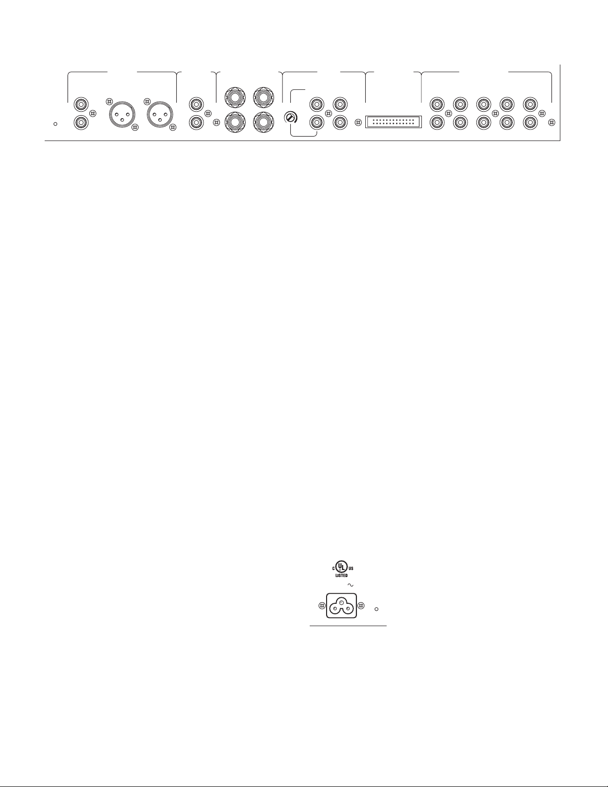
SEND Outputs are unbalanced standard ¼" tip-sleeve jacks.
ey provide a line level Output for external signal processing or
effects units. If effects are not being used, these outputs may be
used as Auxiliary Outputs.
EFFECTS LOOP RETURN ¼" jacks
RETURN Inputs are unbalanced standard ¼" tip-sleeve jacks.
ey provide the Input from external signal processing or effects
units. Switching jacks are used so there is no loss of signal if the
front panel EFFECTS LOOP switch is active with no effects
connected. RETURN Inputs are not appropriate for Auxiliary
Inputs as this signal is only selected when the front panel EFFECTS LOOP switch is active, at which time Master signal is
derived only by the signal present at the RETURN Inputs, the
mix signals are disconnected.
BOOTH OUTPUT RCA jacks
e unbalanced stereo BOOTH OUTPUT is normally used for
booth monitoring. As previously outlined, very flexible source
selection is provided as well as MIC ducking. Remember, the
BOOTH OUTPUT is attenuated by 12 dB whenever one of the
front panel MIC ENGAGE switches is active (unless ducking
has been defeated with the internal jumper. See Mic/Line Inputs
on page Manual-6).
AUX INPUTS 1-5 RCA jacks
ese five stereo AUX Inputs are unbalanced, line level Inputs
available for selection on all six Input channels.
XP 2016S EXTERNAL PROCESSOR
e XP 2016S port provides the required socket for connecting
the ribbon cable (supplied with the optional XP 2016S). If an XP
2016S is not connected, the front panel XP 2016S engage switch
has no effect. If ribbons longer than that supplied with the XP
2016S are used, crosstalk may increase and immunity to RF,
magnetic and conducted interference may be compromised —
don’t do it.
TAPE OUTPUT – PRE-EFFECTS RCA jacks
is unbalanced line-level Output is located before the EFFECTS LOOP and tone controls for recording the Master Mix.
MIC Inputs are mixed as any other source and will be present at
both TAPE OUTPUTS.
TAPE OUTPUT – POST-EFFECTS RCA jacks
is unbalanced line-level Output is located after the EFFECTS
LOOP and before the tone controls. is may be used as an
Auxiliary Output. For this application, as well as for more flexibility when recording, a LEVEL control has been provided as
described below.
HOUSE OUTPUT jacks
Both balanced (XLR) and unbalanced (RCA) jacks are provided.
For long runs, we highly recommend using the balanced XLR
outputs. e unbalanced RCA outputs are intended for short
runs of less than 10 feet (3 meters). Both may be used simultaneously if required.
TAPE OUTPUT – POST-EFFECTS LEVEL control
is adjusts the POST-EFFECTS TAPE OUTPUT from unity
gain to off, allowing optimum sensitivity adjustment for recording or for an Auxiliary Output.
POWER IEC jack
Connects anywhere in the world to AC
line voltage, 100-240 VAC.
Manual-5
Page 6

OPERATION
Mix Level Taper
Rotation
10
10
0
20203030404050506060707080
80
100
100
90
90
Attenuation
RIAA PHONO/LINE INPUTS
Input channels 1 through 4 each have a dedicated preamplifier.
A rear panel switch allows setting these preamps for PHONO
or LINE level signals. Make sure you have the switch in the correct
position for your application. e source selectors for Input channels 1 - 4 may select the dedicated PHONO / LINE preamplifier
or one of the five stereo AUX Inputs as the source.
With normal program material playing, set the INPUT
GAIN control to a level that causes the SIG / OL indicator to
flash green. e SIG / OL indicator should not flash red. is
will ensure optimum signal to noise ratio and dynamic range. If
INPUT GAIN controls are set too high, you may not have the
required headroom for mixing multiple Inputs. If your levels are
set too low, signal-to-noise ratio is compromised.
In addition to optimizing noise and dynamic range, properly setting INPUT GAIN allows the MIX LEVEL control to
operate predictably over its entire range. e taper of the MIX
LEVEL control is non-linear and will have different attenuation
verses rotation characteristics depending on its position. As can
be seen in the figure below, if you are mixing between 30% and
60% of rotation, MIX LEVEL will behave much differently than
if operated between 65% and 95% of rotation.
the INPUT GAIN SIG / OL indicator to accurately indicate the
signal level. Adjust the MIC GAIN so the red OL indicator just
stays off during the highest signal peaks (if a microphone is in
use, yell into it). e MIC GAIN control should only have to be
set once for the source in use. Use the front panel INPUT GAIN
control for trimming the gain after installation.
Next adjust the rear panel MIC 1 and MIC 2 BASS and
TREBLE controls for the desired tonal quality. If you add a lot
of BASS or TREBLE boost, you may want to readjust the MIC
GAIN control to avoid possible overloading.
MIC 1 and MIC 2 each have an ENGAGE switch to the
right of the Input Selector. For a mic signal to be active, the
selector must be set to MIC and the MIC ENGAGE switch set
to ENGAGE (up).
When either of the switches is set to the ENGAGE position, the BOOTH OUTPUT is ducked (attenuated) by 12 dB
th
(about ¼
) to reduce potential feedback. If you do not want the
BOOTH OUTPUT to duck when a MIC source is engaged,
you can remove the top cover and set the internal jumper accordingly. ere is an independent Ducker select jumper for MIC 1
and MIC 2.
It sounds like a lot of trouble to set the input stages up correctly, however, you will be amazed at how much better your
performance sounds.
MIC / LINE INPUTS
Input channels 5 and 6 each have dedicated preamplifiers. A rear
panel switch allows setting these Inputs for MIC or LINE level
signals. Make sure you have the switch in the correct position for
your application. While these Inputs are designed for use with
dynamic microphones (no phantom power) or wireless microphones with line level output, they will accept just about any
mono signal. While balanced operation is highly recommended,
these Inputs may be operated unbalanced with short cables to
the source (less than 10 feet or 3 meters). e source selectors for
Input channels 5 and 6 may select the dedicated MIC / LINE
preamplifier or one of the five stereo AUX inputs.
Prior to permanent installation, adjust the preamplifier
GAIN, BASS and TREBLE controls (located on the rear panel)
for the intended source.
a rear panel MIC GAIN trim. To properly set the MIC GAIN,
In addition to the MIC / LINE switch, each preamplifier has
set the front panel INPUT GAIN control to “10.” is allows
MIX LEVEL
With the Input stages properly adjusted, you are free to use the
MIX LEVEL control for mixing. For most applications, channels
will be mixed at about 70% to 100% rotation. BOOTH and
HOUSE level controls then set the output volume. e MASTER SIG / OL indicator displays the signal level of the mix. e
Green SIG indicator should flash or remain on. e Red OL
indicator should remain off (it may flash occasionally, but if it is
on every beat it is too hot). To correct an overload condition, one
or more of the MIX LEVEL controls must be turned down. e
MASTER SIG / OL indicator monitors the signal before and
after the tone control, so if you use a lot of boost, remember to
monitor this indicator.
TONE CONTROLS
e MP 2016S uses high-performance tone control circuits
that isolate the signal into three bands. e level of each band
is independently controlled, and then recombined. is topology provides full “kill” for TREBLE, MID and BASS. If all
three bands are set to the same level, there will be no change in
frequency response, only amplitude. It is the difference in settings
that determines the tonal quality of the signal. ese advanced
tone controls provide excellent dynamic response with fixed
phase shift. Control is smooth and predictable. e tone controls
can isolate beats, vocals and “high-hat,” as well as adjust general
tonal quality. Remember that the dedicated Mic tone controls
(on the rear panel) are used to equalize the Microphone Inputs.
Manual-6
Page 7
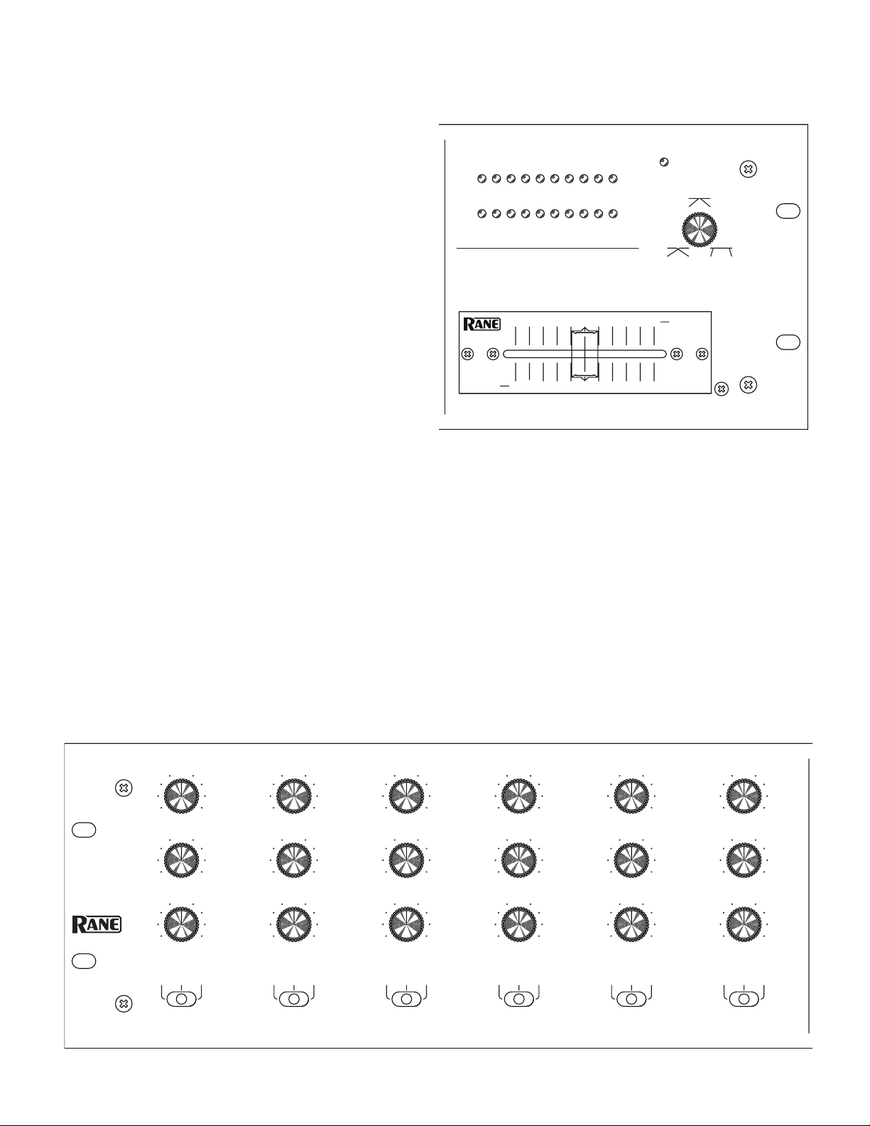
OPTIONAL XP 2016S EXTERNAL PROCESSOR
A POST BA POST BA POST BA POST BA POST BA POST B
BASS
MID
TREBLE
1
BASS
MID
TREBLE
2
BASS
MID
TREBLE
3
BASS
MID
TREBLE
4
BASS
MID
TREBLE
5
BASS
MID
TREBLE
6
CUE METER
+6OFF
0
+6OFF
0
+6OFF
0
+6OFF
0
+6OFF
0
+6OFF
0
+6OFF
0
+6OFF
0
+6OFF
0
+6OFF
0
+6OFF
0
+6OFF
0
+6OFF
0
+6OFF
0
+6OFF
0
+6OFF
0
+6OFF
0
+6OFF
0
-20 -7-10 -4 0-2 +2 +7+4 +10
10 864
A
F 60X
CROSSFADER
CONTOUR
RIGHT / PGM
LEFT / CUE
POWER
CUE METER
XP 2016S
EXTERNAL
PROCESSOR
-20 -7-10 -4 0-2 +2 +7+4 +10
6420
10 864
108
20
A
B
F 60X
Combining the optional XP 2016S EXTERNAL PROCESSOR
with the MP 2016S adds three-band, full-cut, Accelerated-Slope™
tone controls and A-POST-B Crossfader Assign switches for
each of the six Input channels. You also get a high-performance
Active-Crossfader™ with full-range Contour control and a stereo
10-segment peak dBu Master / Cue Meter with peak hold. With
these added features, the system accommodates the diverse needs
of virtually all DJ mixing styles.
e post MIX LEVEL signals from the MP 2016S are routed
to the XP 2016S, processed by the tone controls, then assigned to
the A side of the fader, B side of the fader or post fader. e mixed
signal is returned to the MP 2016S. If the XP 2016S engage
switch is active, the MASTER signal gets the XP 2016S mix. If
the XP 2016S engage switch is not active, the MASTER signal
just gets the MP 2016S mix.
CHANNEL 1-6 TREBLE
Allows adjusting the amplitude of frequencies above 4 kHz from
+6 dB to OFF (full kill).
CHANNEL 1-6 MID
Allows adjusting the amplitude of frequencies between 300 Hz
and 4 kHz from +6 dB to OFF (full kill).
CHANNEL 1-6 BASS
Allows adjusting the amplitude of frequencies below 300 Hz
from +6 dB to OFF (full kill).
CHANNEL 1-6 A/POST/B Assign
ese switches assign each of the six input channels to the A side
of the Crossfader, B side of the Crossfader or POST Crossfader.
CROSSFADER
is implements using Ranes’ proprietary Active Crossfader™
design. All audio is isolated from the control element, greatly
extending the life and performance of the control. See page
Manual-8 for cleaning and replacement instructions.
CROSSFADER CONTOUR
is control allows adjusting the “shape” of the Crossfader response from a gentle curve for smooth long running fades, to the
steep pitch required for performance cut and scratch effects. (See
the graph in the Data Sheet.)
PEAK PROGRAM / CUE METER
e stereo 10-segment Cue Meter on the XP 2016S monitors the
same signal as the headphones. See the HEADPHONE MONITOR section on page Manual-3.
POWER indicator
is yellow indicator lights whenever AC power is connected.
Manual-7
Page 8

MP 2016S Mixer Port
MP 2016S
MIXER
ACN 001 345 482
U.S. PATENT 7,043,032
MADE IN U.S.A.
RANE CORP.
XP 2016S
COMMERCIAL AUDIO
EQUIPMENT 24TJ
R
100-240 V
50/60 Hz 12 WATTS
This device complies with Part 15 of the FCC Rules. Operation is
subject to the following two conditions: (1) this device may not cause
harmful interference, and (2) this device must accept any interference
received, including interference that may cause undesired operation.
is is the required socket to connect the XP 2016S to the MP
2016S, using the ribbon cable supplied with the XP 2016S. If
a ribbon longer that that supplied with the XP 2016S is used,
crosstalk may increase, and immunity to RF, magnetic and conducted interference may be compromised. So don’t do it!
POWER
is power jack receives the cable from the RS 1 power supply
shipped with the unit. e chassis ground screw located just
above the jack is intended for earth grounding the chassis (see
the Chassis Grounding note on page Manual-4).
XP 2016S Ribbon Connections: (PIN 1 marked Ñ)
1) GND
2) GND
3) MIX RIGHT OUT
4) MIX LEFT OUT
5) GND
6) METER LEFT IN
7) METER RIGHT IN
8) GND
9) CH 6R IN
10) CH 6L IN
11) GND
12) CH 5R IN
13) CH 5L IN
14) GND
15) CH 4R IN
16) CH 4L IN
17) GND
18) CH 3R IN
19) CH 3L IN
20) GND
21) CH 2R IN
22) CH 2L IN
23) XP 2016 ENABLE (GND)
24) CH 1R IN
25) CH 1L IN
26) GND
Fader Cleaning
With heavy use in harsh environments, the faders may need
lubrication. is treatment extends longevity and can make used
faders as good as new. e fader assembly must be removed from
the XP 2016S for proper cleaning. We recommend any of the
following cleaning solutions:
Caig DeoxIT FaderLube
Caig DeoxIT FaderLube F5 spray cleaner (ww w.caig.com)
CRC 2-26 (www.crcindustries.com)
Order DeoxIT® from:
CAIG Laboratories, Inc.
12200 atcher Ct.
Poway, CA 92064
Phone 858-486-8388
Fax 858-486-8398
Web www.caig.com
CLEANING INSTRUCTIONS
A. Fader assembly removal
1. Remove (2) 3mm screws.
2. Draw fader assembly out through hole.
3. Remove ribbon cable.
B. Fader cleaning
1. Hold the fader assembly away from the mixer.
2. Position the fader at mid-travel.
3. Spray cleaner/lubricant into both ends of the fader.
4. Move the fader over its full travel back and forth a few times.
5. Shake excess fluid from the fader assembly.
6. Wipe off excess fluid.
F100 spray lubricant (www.caig.com)
©Rane Corporation 10802 47th Ave. W., Mukilteo WA 98275-5098 TEL 425-355-6000 FAX 425-347-7757 WEB www.rane.com
Manual-8
 Loading...