

Page 1
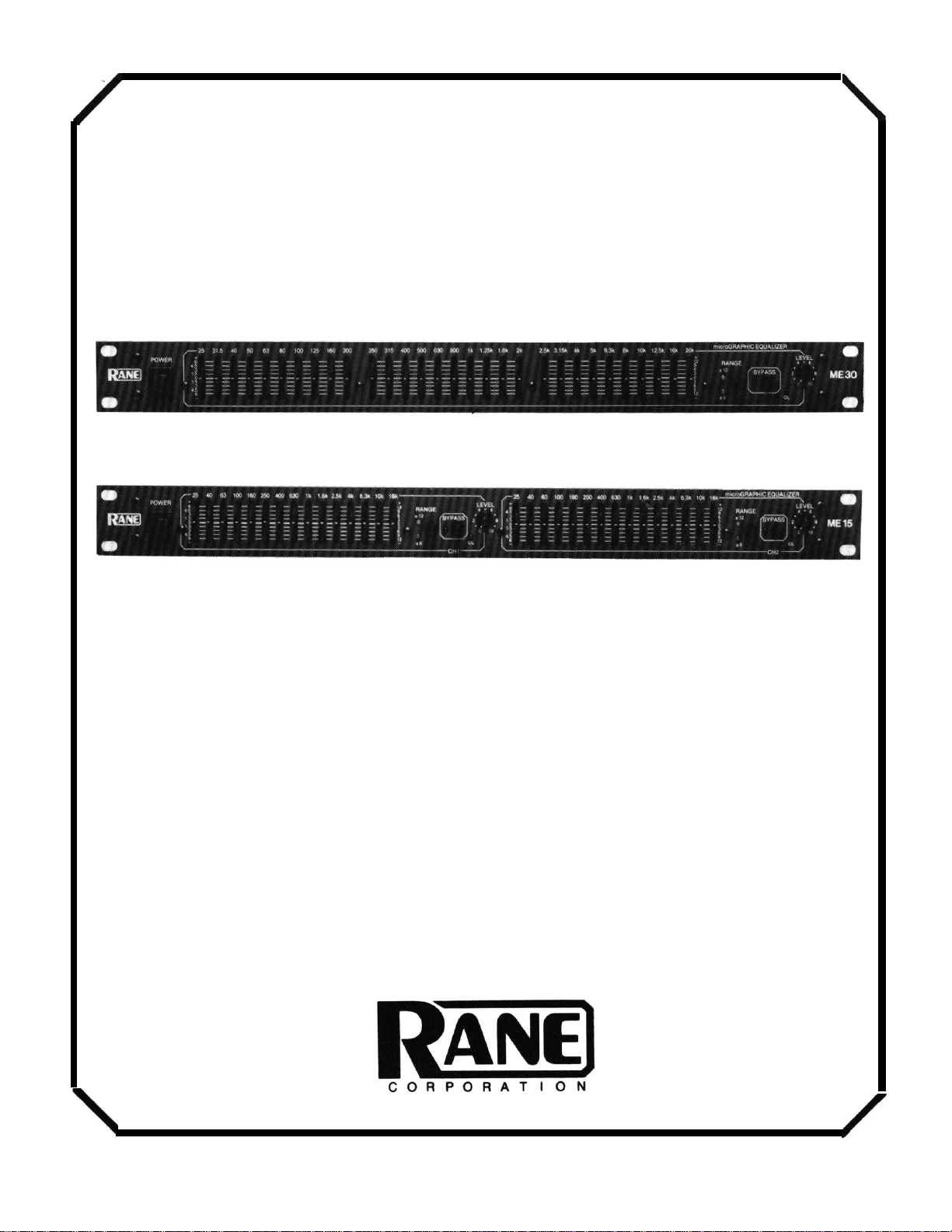
ME 15 and ME 30
OPERATING
AND
SERVICE MANUAL
Page 2
II. PANEL DESCRIPTIONS
FRONT PANEL DESCRIPTION
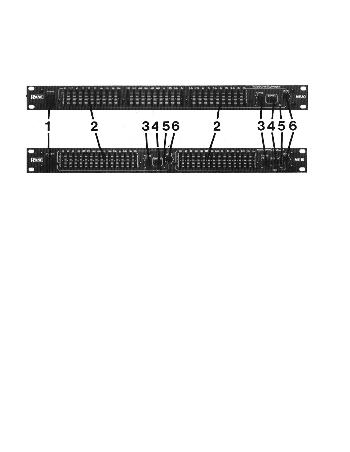
1. POWER SWlTCH: As you have astutely surmised by now, this switch powers up the ME 15 or
ME 30. Note: “power” in this context refers to electrical power, as opposed to political,
financial (often related to the previous), psychic or supernatural.
2. FILTER LEVELSLIDE CONTROLS: Each of these sliders controls the output level of each of
the 30 bandpass filters. Center position is grounded for guaranteed flat response.
3. FILTER RANGE SWITCH: The gain range of the filter sliders is switchable (as a group) from
±6 dB for high resolution, to ±12 dB for maximum boost/cut capability.
4. BYPASS SWITCH: When the red LED is lit, this indicates that the unit or channel is in the
bypass mode: signal is routed directly from the input to the output without passing through
any active circuitry (often referred to as “hard-wire bypass”). Use this switch to compare
equalized and un-equalized material, or to bypass the EQ section in the event of power loss or
unit failure.
5. OVERLOAD INDICATOR: This red LED lights up if any section of the ME 15/30 is within 4 dB
of clipping. Occasional blinking of this LED is acceptable, but if it remains on more than
intermittently you should turn down either the equalizer’s level control(s) or reduce the
output level of the preceding component to avoid audible distortion.
6. LEVEL CONTROL: This controls the level of signal coming into the ME 15 /ME 30. Turn this
control down if the Overload LED lights up steadily (meaning too strong an input signal). Since
actual unity gain depends on varying slider settings (which is why we have not marked a unity
gain position on the front panel), use the bypass switch to determine the exact unity gain
position of this level control by comparing EQ and bypass volumes.
Page 3

REAR PANEL DESCRIPTION
1. INPUT JACK: This is a stereo 1/4" jack which will accommodate either balanced or
unbalanced input signals. For unbalanced signals use a mono 1/4" plug (single conductor with
shield). For balanced signals use microphone cable (two conductor with shield) with a stereo
1/4" plug on one end for the ME 15/30, wired as described below, and either a stereo 1/4" or
three-pin connector as dictated by the signal source on the other end. Rane adheres to the
international and U.S. standard for balanced pin configurations:
Pin #1 = Case ground (Neutral) = Sleeve on a 1/4" connector
Pin #2 = Hot (Positive) = Tip on 1/4" connector
Pin #3 = Signal Ground (Negative) = Ring on 1/4" connector
2. OUTPUT JACK: This is a stereo 1/4" “floating” output which is compatible with either
balanced or unbalanced systems. For balanced systems, use a microphone cable wired as
explained in #1 above.
IMPORTANT: For unbalanced operation, do not use a mono plug (single conductor with
shield) but rather a microphone cable (TWO conductor with shield). Although a mono cord
will work, there is a much greater possibility of hum or buzz creeping into the system with this
type of cord. To minimize hum or buzz problems, wire a microphone cable as shown below
with the following configuration:
From ME 15/30
Tip
Ring
Sleeve (Shield)
The theory here is to GROUND THE SHIELD ONLY AT THE RECEIVING END OF THE CABLE.
The sleeve connection at the output of the ME 15/30 is not connected internally (thus the
term “floating”). For further information on grounding systems ask your dealer for a free copy
of Rane Note 110 entitled “Sound System Interconnection”.
TO
Unbalanced Equipment
Tip
Sleeve
Sleeve
Page 4

III. SYSTEM CONNECTION
Exactly WHERE you install your ME 15 or ME 30 into a sound system can significantly effect
such things as hum, noise, system headroom, compressor/limiter performance and other
factors that influence overall sound quality. Both WHAT and WHY you are equalizing will also
determine where you install it. We’ll leave the WHEN and WHO entirely up to you.
1. WHAT AND WHY. Most outboard equalizers are used to correct and/or enhance the
acoustical performance of a sound system: everything is under control until the program
material reaches the speakers--then trouble begins. EVERY speaker system reacts drastically
different in each room in which it’s located, resulting in feedback problems, absorption nodes,
resonances and everything else short of chicken pox. This is where the equalizer comes in-to
alter the ELECTRICAL performance of the program material in order to COMPENSATE for the
ACOUSTICAL PROBLEMS in the system. This seems very basic, but many fall victim to misuse
of the system equalizer: boosting several low frequency filters when a simple boost of the bass
guitar controls is what’s really needed. Don’t use the system equalizer to make specific tonal
changes in vocals or instruments; use the MIXER EQ controls for this.
2. WHERE. Since most equalizers are used for acoustical correction, the equalizer should be
one of the LAST pieces of gear in front of the amplifiers and active crossovers. Any further up
the line may cause electrical mismatch with other line level equipment.
Here are a few GENERAL guidelines which may be useful in deciding exactly where to install
the ME 15/30 in the system.
1. DOWNSTREAM OF ANY COMPRESSOR/LIMITER. Since system EQ is aimed at the
ACOUSTICAL problems, it should be installed AFTER any compressor/limiters, which are
designed to operate on electrical program material. For one thing, the equalizer slider settings
will change with each new location, which in turn would affect the control voltage and
threshold responses of any compressor/limiter it is driving and render it inconsistent.
Secondly, healthyamounts of boost will often strain the dynamic range of compressor/limiters
and increase the danger of distortion and/or overload.
2. AFTER ANY SYSTEM GAIN Here is a trap many will fall into: mixer, compressor/limiter,
equalizer, active crossover and power amplifier--all with gain controls, and all working
AGAINST each other. The ME 15/30 has incredibly low noise levels, but it IS a line level, active
component. If you have the ME 15/30 level control way down (to avoid overdriving the
compressor/limiter which is wrongly connected AFTER it), then you must turn UP the limiter,
crossover and amplifier controls to compensate; now you’ll blame the equalizer for being too
noisy. Whenever headroom will allow, try to take all the gain you can right at the mixer, and run
unity levels from there on. This should give better noise performance from the mixer, as
well. Connect the ME 15/30 just before the amplifier or active crossover if one is used. Take any
required line gain before and/or in the ME 15/30; avoid taking a lot of gain in the crossover or
power amps as this may create noise or hum problems.
3. BE CAREFUL WITH SEND/RECEIVE LOOPS. Mixers, mixer/preamps and the like often
provide send/receive loops for additional effects or EQ, and the ME 15/30 will work well in this
situation. Just be sure to keep input trim or gain controls turned up as far as the mixer input
headroom will allow, to avoid taking excessive gain downstream and creating noise problems.
Remember to feed the ME 15/30 with roughly line level program (between -10 dBV and
+4 dBm to +20 dBm), and all should work fine.
Page 5

IV. OPERATING PROCEDURES
The ME 15 and ME 30 are extremely accurate, professional quality instruments capable of
precise equalization down to a fraction of a dB. You can expect several advantages from your
constant-Q equalizer over conventional designs: Moving one sliderwill not affect neighboring
filters as much, so you won’t spend time re-adjusting sliders (we call this “equalizing the
equalizer”). You’ll be able to obtain better feedback control without losing sound quality. All
sliders maintain smooth, consistent and accurate calibrated control over filter levels, which is
especially critical in low-profile equalizer designs. Because of this, the overall EQ adjustment
process is significantly easier and more effective.
While a top quality equalizer helps considerably, equalizing a sound system by ear is a VERY
difficult process to achieve successfully, especially in a timely manner. Although the human
ear is very sensitive, it is NOT calibrated, nor constant, and frankly the odds AGAINST a wellbehaved, clear sound system are very great when tuned by ear. Most people know when a
sound system doesn’t sound good; unfortunately they just can’t tell exactly why and where it’s
not right.
BECAUSE OF THlS, WE STRONGLY RECOMMEND THE USE OF A REALTIME ANALYZER TO
PROPERLY EQUALIZE YOUR SYSTEM WITH THE ME 15 OR ME 30.
Forget everything you’ve thought about analyzers and consider this: there’s a new generation
of analyzers which are compact, simple, very easy to operate and surprisingly affordable. Best
of all, they can make a drastic improvement in the overall performance of your sound system
while saving you a great deal of time and effort. (Yes, we just happen to make such an analyzer,
the Model RA 27, but this is not a sales pitch. We are genuinely concerned that you obtain the
best performance from your system. Check around, there are lots of good analyzer designs
available. Get the one you like best.)
A realtime analyzer will help you quickly achieve things nearly impossible by ear: flatten
speaker response, minimize feedback, remove room resonance and allow accurate crossover
alignment. In most cases, simply “normalizing” or “flattening” a sound system is a surprisingly
drastic improvement, but DON’T STOP HERE:
REMEMBER THIS RANE “PRO”VERB: “LOOK, DON’T STOP, AND LISTEN.”
Once you have aligned the system by looking at the analyzer, don’t stop at this point. Listen to
the music program and make any additional adjustments to suit your taste, the type of music
and/or audience. Fatten the bass, sweeten the highs, brighten the mids as you see fit. Since you
are starting from a “tuned” system, your ear will not be fooled into thinking bass is too high
when actually mids are too low, or that highs are too weak when really the mids are too strong.
Fact: analyzers don’t have good taste--people do. Analyzers will consistently and accurately
“tell it like it is”, but ultimately personal judgement determines what sounds good or
appropriate. In fact, final optimum EQ settings, made AFTER analyzer testing, will vary greatly
dependingon the type of music, sound pressure level, size of the venue and disposition of the
audience.
Conclusion: TO CONSISTENTLY OBTAIN THE BEST SOUND FROM YOUR SYSTEM, YOU
NEED TO USE BOTH AN ANALYZER AND YOUR EAR, IN THAT ORDER. The analyzer supplies
the consistency and calibration while your ear supplies good taste.
If obtaining an analyzer is not feasible for you, then you will have to resort to Section 2408,
Paragraph 84-B of the Professional Audio Code, which reads:
“Fiddle with it until it sounds good.”
Page 6

V. SPECIFICATIONS
Constant-Q Bandpass Filters:
ME 15: 2/3 octave bandwidths on precise ISO centers, 25-16 kHz
ME 30: 1/3 octave bandwidths on precise ISO centers, 25-20 kHz
Boost/Cut Range: switchable ±6 dB or ±l2 dB
Built-in Low Cut Filter: -3 dB at 20 Hz (18 dB per octave)
Built-in Ultrasonic Filter: -3 dB at 60 kHz (6 dB per octave)
Overall Gain Range: Off to +6 dB (minimum)
Frequency Response: 20 Hz to 60 kHz, +0/-3 dB
Signal To Noise Ratios: Unweighted, 20 kHz bandwidth
Boost/cut Centered, Unity Gain: 108 dB below +20 dBu
Boost/cut Centered, Maximum Gain: 107 dB below +20 dBu
THD + Noise: Less than .009%, 20 Hz to 20 kHz, @ +4 dBu (1.23V) output
Intermodulation Distortion (SMPTE): less than .005% @ +4 dBu output
Input Impedance: 20,000 ohms
Output Impedance: 100 ohms
Maximum Input Level: +21 dBu (9 Volts)
Maximum Output Level: +21 dBu (9 Volts)
Dimensions: 1.75" H x 19" W x 5.25" rack depth, all steel chassis
Weight: 5 Ib. net
Note: 0 dBu = .775 Volts
 Loading...