

Page 1
DATA S H EET
General Description
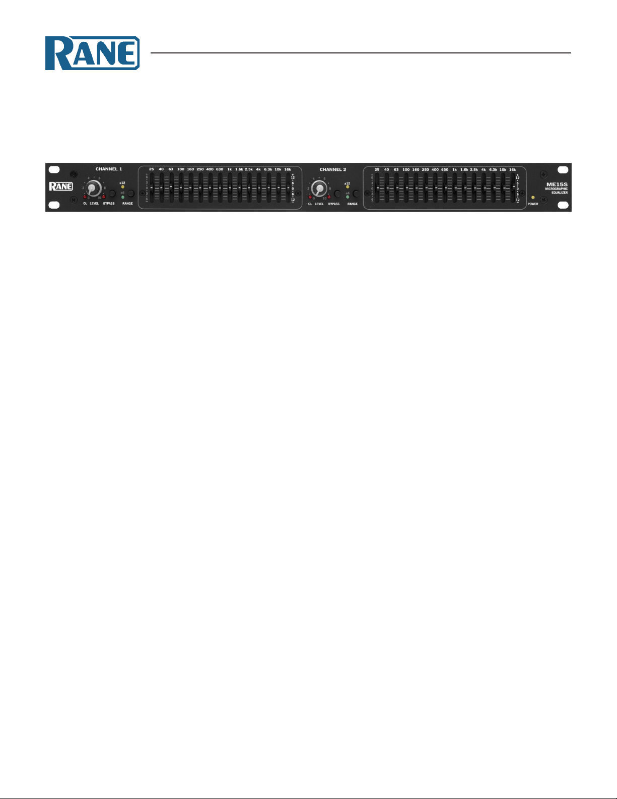
e Rane ME15S microGraphic Equalizer is a two-channel,
⅔-octave design with 20 mm sliders in a single rack space unit.
It features a Range switch for high slider resolution in the ±6 dB
mode, equivalent resolution to 45 mm sliders found on double
rack-space models. e ±12 dB mode provides a wide range of
control over system audio.
e active lter sections feature Rane’s innovative constant-Q
(constant bandwidth) design. Constant-Q means the bandwidth
of each individual lter is guaranteed to be narrow enough to
prevent unwarranted interaction between lters, yet wide enough
to produce exactly the type of correction curve demanded
by even the most unusual acoustic surroundings. is diers
dramatically from conventional designs of the past, encumbered
M E 15 S
microGRAPHIC EQUALIZER
with the unfortunate characteristic of changing bandwidth when
changing boost/cut amounts.
Front panel controls and indicators include an overall rotary
Level control for each channel as well as Overload indicators.
Passive pushbutton Bypass switches feature LED indicators,
avoiding ambiguity by being on when the unit is Bypassed. (A
passive Bypass switch requires no power to operate. is allows
completion of the audio path should power fail in the ME 60S.)
Inputs and Outputs are electronically balanced designs,
capable of unbalanced operation when required. ey accept
and drive all possible signal levels into normal load impedances.
Balanced applications choose between the XLR or ¼" Tip-RingSleeve balanced connectors. Unbalanced sources also may tie to
the ME15S through mono ¼" connectors (no ring connection).
Features
• Constant-Q Bandwidth Design
• Overall Level Control
• 20 mm Filter Slide Controls
• ±6 dB or ±12 dB Slider Range
• Passive Bypass Switch
• Grounded Center Detents at 0 dB
• Infrasonic, Ultrasonic, & RFI Filters
• Fully Balanced XLR Inputs and Outputs
• ¼" TRS Balanced/Unbalanced Inputs and Outputs
• Universal internal switching power supply (100-240 VAC)
Data Sheet-1
Page 2
M E 15 S
microGRAPHIC EQUALIZER
Features and Specifications
Parameter Specication Limit Units Conditions/Comments
Equalizer:
..........Bands (15) ⅔-octave ISO spacing From 25 Hz to 16 kHz
..........Type Constant-Q
..........Accuracy 3 % Center frequency
..........Travel 20 mm Positive grounded center detent
..........Range ±12 or ±6 1 dB Switch selectable
Inputs: Typ e Active balanced/unbalanced
..........Connectors XLR & ¼" TRS
..........Impedance 20k balanced; 10k unbalanced min
..........Maximum Level 20 1 dBu
Outputs: Typ e Active balanced/unbalanced
..........Connectors XLR & ¼" TRS
..........Impedance 400 balanced 200 unbalanced 1%
..........Maximum Level +20 balanced +15 unbalanced 1 dBu 2 k
+19 balanced +13 unbalanced 1 dBu 600
Overall Gain Range O to +0 (unbalanced output) min dB Sliders centered
O to +6 (balanced output) min dB Sliders centered
RFI Filters Yes
Passive Bypass Switches Yes
LED resholds: Overload 4 1 dB Below clipping
Infrasonic Filter 20 Hz, 18 dB/octave, Butterworth 3% Hz
Frequency Response 20 -100 k Hz +0/-3 dB
THD+Noise 0. 011 max % +4 dBu, 20-20 kHz, 20k BW
IM Distortion (SMPTE) 0.01 max % 60 Hz/7 kHz, 4:1, +4 dBu
Signal-to-Noise Ratio re +20 dBu +4 dBu 20 kHz noise bandwidth
107 91 2 dB Sliders centered, unity gain, balanced
92 76 2 dB Full boost, unity gain, balanced
104 88 2 dB Full cut, unity gain, balanced
Channel Separation 85 min dB 1 kHz
Common Mode Rejection 40 1 dB 1 kHz
Unit: Conformity CE, FCC, UL
..........Universal Line Voltage 100-240 VAC 50/60 Hz
..........Maximum Power 7 W
..........Construction All steel
..........Size 1.75" H x 19" W x 5.25" D (1U) (4.4 cm x 48.3 cm x 13.3 cm)
..........Weight 5 lb (2.3 kg)
Shipping: Size 4.25" x 20.3" x 13.75" (10.8 cm x 52 cm x 35 cm)
..........Weight 8 lb (3.6 kg)
Note: 0 dBu=0.775 Vrms
Data Sheet-2
Page 3

Block Diagram
OUTPUT
BYPASS
SWITCH
BYPASS
(NC)
AMPLIFIER
BOOST
TO FILTERS
2-15
25 Hz
BP
CUT
AMPLIFIER
(18 dB/Octave)
LOW
FILTER
20 Hz
LEVEL
(O to +6 dB)
0 dB
RFI
FILTER
INPUT
-6 dB -12 dB +12 dB+6 dB
RANGE
CHANNEL 1
CHANNEL 1
SENSE
OL
OVERLOAD
Constant-Q: Proportional Q:
3dB
1/3 octave 1/3 octave
3dB
3dB
1/3+ octave
3dB
2+ octaves
Bandwidth, dened 3dB down
from peak, remains constant. dramatically with changes in gain.
Bandwidth here changes
FREQUENCY
AMPLITUDE
FREQUENCY
AMPLITUDE
Proportional Q:Constant-Q:
0dB
+3dB
+6dB
1
2
2
1
11
2
2
This design has little
interaction as a
single slider is
moved from
1 to 2. 1 to 2.
moved from
single slider is
aected when a
Both lters are
(both channels identical)
M E 15 S
microGRAPHIC EQUALIZER
Constant-Q
Constant-Q graphic equalizers arose from
the sound professional’s need for greater
control with less interaction than previously possible with conventional equalizers. You use a constant-Q graphic the
same way you use a conventional graphic.
You just get the desired results quicker,
with far less after adjustment to the adjacent sliders.
e accompanying gures dramatically show the advantages of constant-Q
designs. For more technical information,
consult the references on the next page.
Most are available at
www.rane.com/library.html.
Data Sheet-3
Page 4

M E 15 S
microGRAPHIC EQUALIZER
Rear Panel
Architectural Specifications
e graphic equalizer shall be of constant-Q design to minimize
interactions between adjacent bands, and contain frequency
bands located on standard ISO center frequencies. Each band
shall have a bandwidth of ⅔-octave. A switchable boost/cut
range of 12 dB or 6 dB shall be provided. A detented and positively grounded 0 dB point shall be provided on 20 mm linear
sliders with dust dams.
A rotary overall level control shall be provided with a range
from o to +6 dB of gain in balanced mode.
e inputs and outputs shall be active balanced/unbalanced
designs terminated with both XLR and ¼" TRS (tip-ring-sleeve)
connectors. RFI lters shall be provided. e unit shall provide a
passive bypass feature requiring no power to operate. Infrasonic
and ultrasonic lters shall be built-in. LEDs shall be provided to
indicate overload conditions.
e unit shall be capable of operation by means of its own
built-in universal power supply operating at 100-240 VAC and
meet CE requirements. e unit shall be UL and cUL listed. e
unit shall be entirely constructed from cold-rolled steel.
e unit shall be a Rane Corporation ME15S Equalizer.
Available Accessories
• SC 1.7 Security Cover
References
1. D. Bohn, “Constant-Q Graphic Equalizers,” RaneNote, (1982).
2. D. Bohn, “A New Generation of Filters,” Sound and Video Contractor, vol. 2, pp. 36-39 (Feb. 1984).
3. T. Pennington, “Constant-Q,” Studio Sound, vol.27, pp. 82-85 (Oct. 1985).
4. D. Bohn, “Constant-Q Graphic Equalizers,” J. Audio Eng. Soc., vol. 34, pp. 611-626 (September 1986).
5. D. Bohn, “Exposing Equalizer Mythology,” RaneNote, (1986 ).
6. D. Bohn, “Operator Adjustable Equalizers: An Overview,” RaneNote, (19 9 0).
©Rane Corporation 10802 47th Ave. W., Mukilteo WA 98275-5000 USA TEL 425-355-6000 FAX 425-347-7757 WEB rane.com
Data Sheet-4
All features & specications subject to change without notice. 1-2014
 Loading...