

Page 1
OPE RATORS MAN UAL MA 3
MULTICHANNEL AMPLIFIER
QUICK START
Sure, you say, “it's just a three channel amp, I'm in a hurry and I don't need to read the manual.” But at least read this
little section so you really know what to expect, and your installation can go even faster.
Be sure the Amplifier is off before making any connections. Euroblocks make Amplifier connection easy. They are just
like “snap on” terminal blocks. The balanced Input blocks are three-terminal female connectors. The Output blocks are twoterminal female connectors.
Driving the MA 3 from a balanced source is recommended. If you must drive the MA 3 Input with an unbalanced
source, we recommend using a cable that has two conductors plus a shield, and be sure to keep cable lengths as short as
possible (under 10 feet). See Rane Note 110, “Sound System Interconnection” (contained in this booklet).
Nominal speaker loads should be no lower than 4 ohms per Output. If you are running series or parallel combinations,
be sure and check your total load impedance. For constant-voltage distribution, consider using the optional TF 407 (40 W /
70.7 V) or TF 410 (40 W / 100 V) transformer. Transformers may be installed inside the MA 3 on any number of Output
Channels required. If you intend to use constant-voltage distribution transformers, you may want to read RaneNote 136
“Constant-Voltage Audio Distribution Systems” (contained in this booklet).
Once Input and Output connections are completed, be sure all rear panel LEVEL controls are all the way counterclockwise. Now flip the POWER switch on. After a couple of seconds, slowly turn up each Channels’ LEVEL control to the
desired gain. Maximum yields the most effective dynamic range control for the built-in Limiter). If all is well, you will hear
something pleasant. If not, re-check connections, put on a better CD, and read more of the manual.
WEAR PARTS: This product contains no wear parts.
Manual-1
Page 2
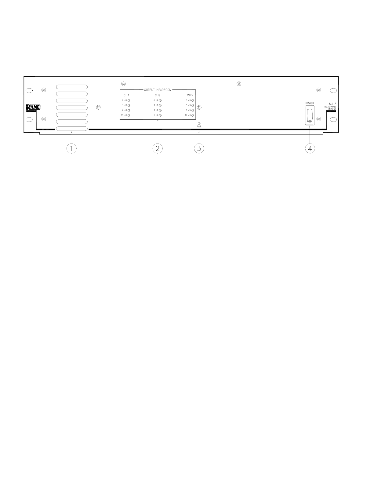
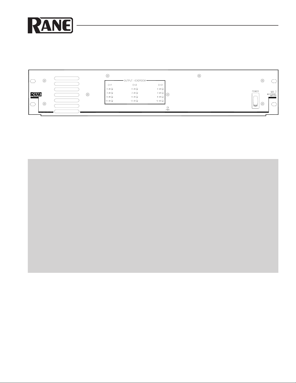
FRONT PANEL DESCRIPTION
Heat tunnel exhaust vents are located on the left of the unit. Large aperture vent slots are used for low noise. Air is taken
in at the back of the unit and exhausts out the front. When installed in a rack, make sure there is ample room for air to exit.
The sealed heat tunnel design does not require the use of an air filter.
OUTPUT HEADROOM meters indicate the amount of remaining headroom (how much more signal can be applied before
Limiting occurs).
0 dB OUTPUT HEADROOM remaining is indicated by a red indicator. When lit, any additional signal causes the Limiter to
operate. It is possible to “compress” the signal as much as 20 dB with very little effect on sound quality. This gives the
MA 3 the overload characteristics of a much larger amplifier, without the use of external compressors. The MA 3 was
designed to be driven hard (heavily compressed signal) so it is not necessary to buy extra power to obtain the headroom
required to prevent overload.
3 dB OUTPUT HEADROOM remaining is indicated by a yellow indicator. When lit, 3 dB of additional signal may be
applied before Limiting.
6 dB OUTPUT HEADROOM remaining is indicated by a green indicator. When lit, 6 dB of additional signal may be
applied before Limiting.
12 dB OUTPUT HEADROOM remaining is indicated by a green indicator. When lit, 12 dB of additional signal may be
applied before Limiting.
PWR: This yellow indicator lights when power is applied to the unit. See below.
POWER switch: This control obediently turns the MA 3 on and off every time you poke it with your finger. Poking the top
half of the switch turns the unit on when it is off. Poking the bottom portion of the switch turns the unit off when it it on. All
three Channels have turn-on and turn-off muting to reduce switching transients.
Manual-2
Page 3

REAR PANEL DESCRIPTION
IEC cord socket: This connector accepts a standard IEC line cord (included with 120 V domestic units). Plug this into a
grounded AC outlet of 120 VAC (or 230 VAC if the MA 3 is internally wired for 230 V operation).
OUTPUTS: Connect the speaker(s) to each of the three Channels by means of the Euroblock connectors with 18 to 12
AWG wire. Each Output may have an optional 70.7V or 100V distribution transformer installed inside the MA 3. These
optional transformers are 40 watt devices with 0.5 dB insertion loss at rated power and a frequency response of 50 Hz to 15
kHz, ±1 dB. The 70.7 V transformer kit is the TF 407. The 100V transformer kit is the TF 410.
INPUTS are balanced Euroblock connectors. We recommend the use of at least 18 AWG wire for reliability. Driving the
MA 3 from a balanced source is recommended. If you must drive the MA 3 Input with an unbalanced source, we recommend
using a cable that has two conductors plus a shield. Connect the (+) or “hot” source to the MA 3 (+) Input, the ground to the
MA 3 (–) Input and connect the shield to the MA 3 shield input. Do not connect the shield on the source end. Shield connections go directly to chassis ground and should not be used as signal ground. Shield connection to chassis occurs via the
screw found between the Input and Output connectors—keep this screw tight for improved EMI protection. When operating
the MA 3 with unbalanced Inputs, be sure to keep cable lengths as short as possible. Refer to RaneNote 110, “Sound System
Interconnection” (included in this booklet) for additional information.
LEVEL controls adjust the input sensitivity for each of the three Amplifiers. The internal Limiters have maximum operat-
ing range (most amount of limiting before input overload) when the LEVEL controls are set to maximum. For best system
noise performance, the input sensitivity may be reduced to send a “hotter” signal to the Amplifier. Here we go again! You
get nothing for free. There are always tradeoffs to be made (better overdrive capability or lower system noise). The choice
depends on your application. For additional information see RaneNote 135 “Setting Sound System Level Controls” available
from our website or upon request from the factory.
FAN SPEED: There are two fan speeds. The NORMAL setting (switch out) allows the MA 3 to deliver full rated continu-
ous average power into 4 ohms, all Channels driven, with ambient room temperature of 22°C. Therefore, it is seldom, if
ever, necessary to run the fan at the FAST speed. The exception might be a very hot environment and heavily compressed
music into a demanding load. The only penalty for running the fan at the FAST speed is noise.
Heat tunnel air intake: The fan draws air in through the finger guard on the rear of the unit. The air flow is directed down
a sealed heat tunnel and exhausts through front panel vents. No filter is required as air flow is directed through an unobstructed, sealed tunnel and will not contaminate internal circuitry.
Manual-3
Page 4

FEATURES & APPLICATIONS
Built to be driven hard
The MA 3 Amplifier drives all three Channels at the
continuous average rated power, indefinitely. It is specifically
designed to operate in demanding commercial applications.
Very low emissions allow the Amplifier to operate in close
proximity to signal processing equipment without causing
excessive interference. The CP 31, CP 52, CP 64 and SRM 66
may all operate next to the MA 3 in a rack. The high efficiency “heat tunnel” design allows the Amplifier to process
severely compressed signals reliably even when installed in a
rack with elevated ambient temperatures. Forced air cooling
keeps heat away from other equipment.
You won't hear other Zones
The MA 3 is designed to deliver foreground music,
background music and paging signals to three different Zones
without annoying crosstalk. A quiet office, for example, with
a paging signal only, will not hear foreground music playing
in the lounge. The high capacity linear power supply incorporates three independent secondary supplies with independent
bridge rectifiers and filters. The result is exceptionally good
crosstalk figures even with multiple channels driving full
power into 4 ohm loads.
No bad “spikes”
The MA 3 is designed to operate without interruption of
signal with as little as 85 VAC available (120 VAC unit).
Even if the Amplifier is operating at full power, the signal
will not breakup as the AC line voltage drops to 85 VAC. If
the AC line drops lower than 85 VAC the signal mutes
without “spikes.” Once AC power is restored, the signal
restarts quickly without “spikes” or signal breakup.
The good “SPiKe”
The power Amplifiers in the MA 3 are protected with
National Semiconductors’ proprietary SPiKe* protection
circuitry. SPiKe protection offers a level of protection not
available in conventional amplifiers. It has the ability to
instantaneously monitor the temperature of the power device
die, yielding a level of reliability not achievable with discrete
designs.
80 Hz Highpass Filters
Internal jumpers allow independently selecting 80 Hz,
nd
2
-order Butterworth Filters for each Channel. These Filters
are useful when using small bookshelf speakers or small
constant voltage distribution transformers.
It’s OK to light the 0 dB Headroom indicator a lot
The high performance Limiter used in the MA 3 means all
the available power can be delivered to the load and not
simply held in reserve to avoid overload. There is no need to
buy up to four times the required power just to prevent
occasional system overload. The MA 3 can compress a signal
with 9 dB of dynamic power range down to a signal with 3 dB
of dynamic power without loss of speech intelligibility or
excessive distortion.
With typical Amplifiers, when 40 watts is needed to
achieve a required average SPL of 80 dB, the contractor must
buy an Amplifier rated at no less than 160 watts just to
maintain 6 dB of headroom. The figure below illustrates the
performance of the MA 3 Limiter.
2
1
THD+N(%)
LEVEL(W)
AMPL(dBu)
MA 3 LIMIT & vs 31 MAR 98 08:52:13
THD & N in %
Power →
0.1
0.020
-5.00 0.0 5.000 10.00 15.00 20.00
← THD & N
Input Level in dBu
Optional constant voltage distribution transformers
Up to three 70.7 V or 100 V constant voltage distribution
transformers may be mounted inside the MA 3. The optional
TF 407 is a 40 watt, 70.7 V transformer with 0.5 dB insertion
loss at rated power and a frequency response of 50 Hz to 15
kHz, ±1 dB. The optional TF 410 is a 40 watt, 100 V transformer with .5 dB insertion loss at rated power and a frequency response of 50 Hz to 15 kHz, ±1 dB. No external
wiring or mounting is required.
*Spike is a registered trademark of National Semiconductor Corporation. SPiKe is an acronym for Self Peak Instanta-
neous (Ke) protection circuitry.
60.00
55.00
50.00
45.00
40.00
Output Power in Watts
35.00
30.00
25.00
20.00
15.00
10.00
©Rane Corporation 10802 47th Ave. W., Mukilteo WA 98275-5098 TEL (425)355-6000 FAX (425)347-7757 WEB http://www.rane.com
Manual-4
105227
Page 5

RISK OF ELECTRIC SHOCK
DO NOT OPEN
CAUTION
IMPORTANT SAFETY INSTRUCTIONS
1. Read these instructions.
2. Keep these instructions.
3. Heed all warnings.
4. Follow all instructions.
5. Do not use this apparatus near water.
6. Clean only with a dry cloth.
7. Do not block any ventilation openings. Install in accordance with manufacturer’s instructions.
8. Do not install near any heat sources such as radiators, registers, stoves, or other apparatus (including ampliers) that produce heat.
9. Do not defeat the safety purpose of the polarized or grounding-type plug. A polarized plug has two blades with one wider than the other. A grounding-type plug has two blades and a third grounding prong. e wide blade or third prong is provided for your safety. If the provided plug does not
t into your outlet, consult an electrician for replacement of the obsolete outlet.
10. Protect the power cord and plug from being walked on or pinched particularly at plugs, convenience receptacles, and the point where it exits from
the apparatus.
11. Only use attachments and accessories specied by Rane.
12. Use only with the cart, stand, tripod, bracket, or table specied by the manufacturer, or sold with the apparatus. When a cart is used, use caution
when moving the cart/apparatus combination to avoid injury from tip-over.
13. Unplug this apparatus during lightning storms or when unused for long periods of time.
14. Refer all servicing to qualied service personnel. Servicing is required when the apparatus has been damaged in any way, such as power supply
cord or plug is damaged, liquid has been spilled or objects have fallen into the apparatus, the apparatus has been exposed to rain or moisture, does
not operate normally, or has been dropped.
15. e plug on the power cord is the AC mains disconnect device and must remain readily operable. To completely disconnect this apparatus from
the AC mains, disconnect the power supply cord plug from the AC receptacle.
16. is apparatus shall be connected to a mains socket outlet with a protective earthing connection.
17. When permanently connected, an all-pole mains switch with a contact separation of at least 3 mm in each pole shall be incorporated in the electrical installation of the building.
18. If rackmounting, provide adequate ventilation. Equipment may be located above or below this apparatus, but some equipment (like large power
ampliers) may cause an unacceptable amount of hum or may generate too much heat and degrade the performance of this apparatus.
19. is apparatus may be installed in an industry standard equipment rack. Use screws through all mounting holes to provide the best support.
WARNING: To reduce the risk of re or electric shock, do not expose this apparatus to rain or moisture. Apparatus shall not be exposed to dripping
or splashing and no objects lled with liquids, such as vases, shall be placed on the apparatus.
NOTE: is equipment has been tested and found to comply with the limits for a Class B digital device, pursuant to part 15 of the FCC Rules. ese
limits are designed to provide reasonable protection against harmful interference in a residential installation. is equipment generates, uses and can
radiate radio frequency energy and, if not installed and used in accordance with the instructions, may cause harmful interference to radio communications. However, there is no guarantee that interference will not occur in a particular installation. If this equipment does cause harmful interference to
radio or television reception, which can be determined by turning the equipment o and on, the user is encouraged to try to correct the interference
by one or more of the following measures:
• Reorient or relocate the receiving antenna.
• Increase the separation between the equipment and receiver.
• Connect the equipment into an outlet on a circuit dierent from that to which the receiver is connected.
• Consult the dealer or an experienced radio/TV technician for help.
CAU TION: Changes or modications not expressly approved by Rane Corporation could void the user's authority to operate the equipment.
is Class B digital apparatus complies with Canadian ICES-003.
Cet appareil numérique de la classe B est conforme à la norme NMB-003 du Canada.
WARNING
To reduce the risk of electrical shock, do not open the unit. No user
serviceable parts inside. Refer servicing to qualied service personnel.
e symbols shown below are internationally accepted symbols that warn
of potential hazards with electrical products.
is symbol indicates that a dangerous voltage
constituting a risk of electric shock is present within
this unit.
is symbol indicates that there are important
operating and maintenance instructions in the
literature accompanying this unit.
 Loading...