

Page 1
HAL
System Installation Guide
Halogen Software Version 6.2
Page 2
HAL
System Installation Guide
IMPORTANT SAFETY INSTRUCTIONS
1. Read these instructions.
2. Keep these instructions.
3. Heed all warnings.
4. Follow all instructions.
5. Do not use this apparatus near water.
6. Clean only with a dry cloth.
7. Do not block any ventilation openings. Install in accordance with manufacturer’s instructions.
8. Do not install near any heat sources such as radiators, registers, stoves, or other apparatus (including amplifiers) that produce heat.
9. Do not defeat the safety purpose of the polarized or grounding-type plug. A polarized plug has two blades with one wider than the other. A grounding-type
plug has two blades and a third grounding prong. e wide blade or third prong is provided for your safety. If the provided plug does not fit into your outlet,
consult an electrician for replacement of the obsolete outlet.
10. Protect the power cord and plug from being walked on or pinched particularly at plugs, convenience receptacles, and the point where it exits from the
apparatus.
11. Only use attachments and accessories specified by Rane.
12. Use only with the cart, stand, tripod, bracket, or table specified by the manufacturer, or sold with the apparatus. When a cart is used, use caution when
moving the cart/apparatus combination to avoid injury from tip-over.
13. Unplug this apparatus during lightning storms or when unused for long periods of time.
14. Refer all servicing to qualified service personnel. Servicing is required when the apparatus has been damaged in any way, such as power supply cord or plug
is damaged, liquid has been spilled or objects have fallen into the apparatus, the apparatus has been exposed to rain or moisture, does not operate normally,
or has been dropped.
15. e plug on the power cord is the AC mains disconnect device and must remain readily operable. To completely disconnect this apparatus from the AC
mains, disconnect the power supply cord plug from the AC receptacle.
16. is apparatus shall be connected to a mains socket outlet with a protective earthing connection.
17. When permanently connected, an all-pole mains switch with a contact separation of at least 3 mm in each pole shall be incorporated in the electrical
installation of the building.
18. If rackmounting, provide adequate ventilation. Equipment may be located above or below this apparatus, but some equipment (like large power amplifiers)
may cause an unacceptable amount of hum or may generate too much heat and degrade the performance of this apparatus.
19. is apparatus may be installed in an industry standard equipment rack. Use screws through all mounting holes to provide the best support.
WARNING: To reduce the risk of fire or electric shock, do not expose this apparatus to rain or moisture. Apparatus shall not be exposed to dripping or
splashing and no objects filled with liquids, such as vases, shall be placed on the apparatus.
WARNING
e symbols shown below are internationally accepted symbols that
warn of potential hazards with electrical products.
CAUTION
RISK OF ELECTRIC SHOCK
DO NOT OPEN
is symbol indicates that a dangerous voltage
constituting a risk of electric shock is present within
this unit.
ATTENTION: RISQUE DE CHOCS ELECTRIQUE - NE PAS OUVRIR
To reduce the risk of electrical shock, do not open the unit. No user
serviceable parts inside. Refer servicing to qualified service personnel.
WARNING: is product may contain chemicals known to the State of California to cause cancer, or birth defects or other reproductive harm.
NOTE: is equipment has been tested and found to comply with the limits for a Class B digital device, pursuant to part 15 of the FCC Rules. ese limits
are designed to provide reasonable protection against harmful interference in a residential installation. is equipment generates, uses and can radiate radio
frequency energy and, if not installed and used in accordance with the instructions, may cause harmful interference to radio communications. However,
there is no guarantee that interference will not occur in a particular installation. If this equipment does cause harmful interference to radio or television
reception, which can be determined by turning the equipment off and on, the user is encouraged to try to correct the interference by one or more of the
following measures:
• Reorient or relocate the receiving antenna.
• Increase the separation between the equipment and receiver.
• Connect the equipment into an outlet on a circuit different from that to which the receiver is connected.
• Consult the dealer or an experienced radio/TV technician for help.
CAUTION: Changes or modifications not expressly approved by Rane Corporation could void the user's authority to operate the equipment.
CAN ICES-3 (B)/NMB-3(B)
Shielded CAT5e or better cables are required in order to comply with the FCC Rules part 15 limits for a Class B digital device.
is symbol indicates that there are important
operating and maintenance instructions in the
literature accompanying this unit.
Page 3
HAL
System Installation Guide
INSTRUCTIONS DE SÉCURITÉ
1. Lisez ces instructions.
2. Gardez précieusement ces instructions.
3. Respectez les avertissements.
4. Suivez toutes les instructions.
5. Ne pas utiliser près d’une source d’eau.
6. Ne nettoyer qu’avec un chiffon doux.
7. N’obstruer aucune évacuation d’air. Effectuez l’installation en suivant les instructions du fabricant.
8. Ne pas disposer près d’une source de chaleur, c-à-d tout appareil produisant de la chaleur sans exception.
9. Ne pas modifier le cordon d’alimentation. Un cordon polarisé possède 2 lames, l’une plus large que l’autre. Un cordon avec tresse de masse possède 2 lames
plus une 3è pour la terre. La lame large ou la tresse de masse assurent votre sécurité. Si le cordon fourni ne correspond pas à votre prise, contactez votre
électricien.
10. Faites en sorte que le cordon ne soit pas piétiné, ni au niveau du fil, ni au niveau de ses broches, ni au niveau des connecteurs de vos appareils.
11. N’utilisez que des accessoires recommandés par Rane.
12. N’utilisez que les éléments de transport, stands, pieds ou tables spécifiés par le fabricant ou vendu avec l’appareil. Quand vous utlisez une valise de
transport, prenez soin de vous déplacer avec cet équipement avec prudence afin d’éviter tout risque de blessure.
13. Débranchez cet appareil pendant un orage ou si vous ne l’utilisez pas pendant un certain temps.
14. Adressez-vous à du personnel qualifié pour tout service après vente. Celui-ci est nécessaire dans n’importe quel cas où l’appareil est abimé : si le cordon ou
les fiches sont endommagés, si du liquide a été renversé ou si des objets sont tombés sur l’appareil, si celui-ci a été exposé à la pluie ou l’humidité, s’il ne
fonctionne pas correctement ou est tombé.
15. La fiche du cordon d’alimentation sert à brancher le courant alternatif AC et doit absolument rester accessible. Pour déconnecter totalement l’appareil du
secteur, débranchez le câble d’alimentation de la prise secteur.
16. Cet appareil doit être branché à une prise terre avec protection.
17. Quand il est branché de manière permanente, un disjoncteur tripolaire normalisé doit être incorporé dans l’installation électrique de l’immeuble.
18. En cas de montage en rack, laissez un espace suffisant pour la ventilation. Vous pouvez disposer d’autres appareils au-dessus ou en-dessous de celui-ci, mais
certains (tels que de gros amplificateurs) peuvent provoquer un buzz ou générer trop de chaleur au risque d’endommager votre appareil et dégrader ses
performances.
19. Cet appareil peut-être installé dans une baie standard ou un chassis normalisé pour un montage en rack. Visser chaque trou de chaque oreille de rack pour
une meilleure fixation et sécurité.
ATTENTION: afin d’éviter tout risque de feu ou de choc électrique, gardez cet appareil éloigné de toute source d’humidité et d’éclaboussures quelles qu’elles
soient. L’appareil doit également être éloigné de tout objet possédant du liquide (boisson en bouteilles, vases,…).
ATTENTION
Les symboles ci-dessous sont reconnus internationalement comme
prévenant tout risque électrique.
CAUTION
RISK OF ELECTRIC SHOCK
DO NOT OPEN
Ce symbole indique que cette unité utilise un voltage
élevé constituant un risque de choc
électrique.
ATTENTION: RISQUE DE CHOCS ELECTRIQUE - NE PAS OUVRIR
Afin d’éviter tout risque de choc électrique, ne pas ouvrir l’appareil.
Aucune pièce ne peut être changée par l’utilisateur. Contactez un SAV
qualifié pour toute intervention.
REMARQUE: Cet équipement a été testé et approuvé conforme aux limites pour un appareil numérique de classe B, conformément au chapitre 15 des
règles de la FCC. Ces limites sont établis pour fournir une protection raisonnable contre tout risque d’interférences et peuvent provoquer une énergie de
radiofréquence s'il n'est pas installé et utilisé conformément aux instructions, peut également provoquer des interférences aux niveaux des équipements de
communication. Cependant, il n'existe aucune garantie que de telles interférences ne se produiront pas dans une installation particulière. Si cet équipement
provoque des interférences en réception radio ou télévision, ceci peut être detecté en mettant l'équipement sous/hors tension, l'utilisateur est encouragé à
essayer de corriger cette interférence par une ou plusieurs des mesures suivantes:
• Réorienter ou déplacer l'antenne de réception.
• Augmenter la distance entre l'équipement et le récepteur.
• Connecter l'équipement à une sortie sur un circuit différent de celui sur lequel le récepteur est branché.
• Consulter un revendeur ou un technicien radio / TV expérimenté.
ATTENTION: Les changements ou modifications non expressément approuvés par Rane Corporation peuvent annuler l'autorité de l'utilisateur à manipuler
cet équipement et rendre ainsi nulles toutes les conditions de garantie.
CAN ICES-3 (B)/NMB-3(B)
Ce symbole indique la présence d’instructions
d’utilisation et de maintenance importantes dans le
document fourni.
Cartons et papier à recycler.
Un câble blindé de CAT5 ou de qualité équivalente voir meilleure sont nécessaires afin de se conformer à
la réglementation de la FCC chapitre 15 sur les limites concernant les appareils numériques de classe B.
Page 4

Table of Contents
CHAPTER 1: Getting Started 1
The Installation Workflow 1
Introduction to the HAL System 4
System Requirements 7
Minimum Requirements for Running Halogen 7
Recommendations for Best Performance 7
Administrative Rights Requirements 8
Required Ports 8
Required Processes 9
Using the HAL System Documentation 10
CHAPTER 2: Hardware Component Details 13
Overview of HAL Devices 13
Available HAL Models 13
HAL Front and Rear Panels 14
Discontinued HAL Models 20
Remote Audio Devices 23
How the shielded CAT 5e Cabling is Utilized 23
RADGrounding 24
The Parts of a RAD 26
PAGER1 RAD 28
RAD16z 29
AM1 and AM2 RADs 32
RAD26 - One RoomRAD 33
RAD27 - USB Audio 39
Discontinued RAD Models 43
Digital Remote Devices 43
DRGrounding 44
Available Digital Remote Models 45
iii
Page 5

HAL SYSTEM INSTALL GUIDE
Infrared Remote Devices 62
IR2 Device 62
Expansion Units 63
HAL1x Expansion Units 64
Discontinued EXP Models 66
Shielded CAT 5e Cable Requirements 67
Momentary and Latching Toggle Configuration 68
CHAPTER 3: Installing Your HAL System 72
Task 1: Install and Connect HAL 72
Task 2: Configuring HAL 74
Task 3: Pulling and Terminating shielded CAT 5e Cabling 76
Task 4: Installing and Connecting HAL Expansion Units 76
Task 5: Installing and Connecting RADs and DRs 78
Task 6: Installing and Connecting Analog Devices 83
Task 7: Verify and Troubleshoot Installation 83
CHAPTER 4: Introduction to the Halogen Software 87
Basic Structure 87
Workspace Layout 88
Installing and Starting the Halogen Software 89
Uninstalling the Halogen Software 91
Upgrading Halogen Software and HAL Firmware 92
Generating Device Labels 94
Generating Hardware Lists 96
Locating a Device 96
Swapping Hardware Devices 98
CHAPTER 5: Troubleshooting Your HAL System Installation 101
Troubleshooting the HAL Hardware 101
Troubleshooting RAD Devices 103
Troubleshooting DR Devices 104
iv
Page 6

Troubleshooting EXP Devices 106
Troubleshooting the HAL Connection 107
Using Meters to Troubleshoot 111
Rane Technical Support 111
Index 112
Warranty Information 116
Declaration of Conformity 118
v
Page 7

CHAPTER 1: Getting Started
Welcome to the world of HAL!
To help you get started with the installation of the HAL System, we have provided a simple breakdown of the key
installation tasks—presented in the recommended order. If you are new to the HAL System, we recommend that
(after reviewing this workflow) you spend a few moments reviewing the basics of the system before actually beginning the installation. We understand that your job is to get this system installed as quickly and efficiently as possible, but a slight detour to review the product details is well worth your time. See "Introduction to the HAL
System" on page 4.
The Installation Workflow
There are seven key tasks involved in the installation of a HAL System. An overview of each task is listed below,
along with page references to the specific details for each task. We recommend that you review this entire list to
get a sense of the work flow, and then return to the first task to begin the actual installation process. Note that the
order of some of these tasks can vary. See each task description for more details.
Task 1: Install and connect the HAL.
This task involves the physical attachment of the HAL hardware to your audio rack. You can perform this task offsite or on-site. Once installed, you then connect other devices to the HAL and, if necessary in your environment,
connect the HAL to your Ethernet network. If you are installing onsite, you may want to pull and terminate the
shielded CAT 5e cabling first (see "Task 3: Pulling and Terminating shielded CAT 5e Cabling" on page 76) so
that the cables are ready to connect to the HAL. For details on installing the HAL, see "Task 1: Install and Connect HAL" on page 72.
Task 2: Configure the system.
Before the system can function properly, you must configure the hardware (the HAL, EXPs, RADs, and DRs) as
well as the audio processing and path. You perform this configuration using the Halogen software that is shipped
with the HAL hardware. (The software is also available on the Rane website at rane.com/hal.) You can configure
the system by loading a configuration file that contains the appropriate hardware settings, audio flow, and processing; or you can create the configuration directly on a live device. We strongly recommend using a con-
figuration file as a starting point!
In most cases, the audio designer will have already created this configuration file, which makes your installation
job much easier. All you have to do is load the file into the HAL device. For the purposes of this guide, we have
assumed this scenario—that the configuration file has already been created for you. If not—well, you’re going to
need to do a little more reading. You can find additional information about configuration files in the Halogen
Help System (accessed from the Halogen software) as well as in the HAL System Design Guide (available on your
product DVD as well as on the Rane website).
NOTE: If the final configuration is to be completed later, but you merely want to install the equipment and
make sure the system can send and receive audio, you can create a very simple configuration to accomplish
this. See "Creating a Verification Configuration" on page 85 for more information.
Regardless if you’re creating a new configuration or simply loading a pre-defined configuration, you will need to
install, start, and use the Halogen software.
1
Page 8

HAL SYSTEM INSTALL GUIDE
NOTE: Where this configuration task falls in the installation process is somewhat flexible. If you prefer, you
can install and connect the RADs, DRs, and EXPs prior to loading the configuration file. There are advantages, however, in loading the configuration first. Whether or not the configuration is loaded, as long as the
HAL is powered on and connected prior to installing the peripheral devices, you can determine immediately
upon installing a RAD, DR, or EXP (by observing its status indicators) if it is functioning properly. But if
the configuration is also in place, you can immediately determine if the EXP, RAD or DR model you just
installed matches the model specified in the HAL configuration (if there’s a mismatch, the EXP's front panel
LED's flash, the RAD’s LEDs flash red and the DR's LCD screen displays Configuration Mismatch). Also, if
you have wireless access to the HAL, loading the configuration file early in the process makes it possible to
then view the configuration from a laptop as you’re installing the RADs, DRs, and EXPs. If you do not have
a configuration file and you plan to simply test that the installed equipment can successfully send and
receive audio, disregard this recommendation. You will create a simple test configuration after you have
installed all of the equipment.
Task 3: Pull and terminate the shielded CAT 5e cabling for the EXPs, RADs and DRs.
Each EXP, RAD and DR connects to the HAL via a shielded CAT 5e cable. We recommend pulling this cable
prior to installing the RADs and DRs. Doing so makes it much easier to troubleshoot their installation. Note that
each RAD and DR requires a home run. As noted in the previous task, if the shielded CAT 5e cables are installed
and terminated, and the HAL is powered on and connected, you can verify if the RADs and DRs are working properly as soon as you connect them. For details on this task, see "Task 3: Pulling and Terminating shielded CAT 5e
Cabling" on page 76.
Task 4: Install and connect HAL Expansion Units (if needed).
If your system requires one or more Expansion Units (EXPs), you should install and connect them to the HAL
before beginning the installation of your Remote Audio Devices (RADs) and Digital Remotes (DRs). This task
involves using shielded CAT5e cable to connect each EXP in a daisy-chained fashion. That is, connecting the
first EXP to HAL, connecting the second EXP to the first EXP, and so on. For details, see "Task 4: Installing and
Connecting HAL Expansion Units" on page 76. It is important that you install the correct EXPmodel in each location and in the correct order in the daisy-chain. If you load the HAL configuration prior to installing the EXPs,
you can view the status indicators to determine if you have installed the correct model. If the models do not match,
the front panel LEDs on the EXP flash. You can also see this status in Halogen's Hardware Workspace.
The older HAL1 system used a FireWire based expansion bus. This bus allowed you to connect up to four EXP1
expansion units in a daisy-chained manner. For details see "Task 4 (legacy): Installing and Connecting HAL1
Expansion Units" on page 1.
Task 5: Install and connect the individual RADs and DRs.
This task involves the connection of the RADs and DRs to the shielded CAT 5e cable, followed by the physical
installation of the RADs and DRs into the switchboxes in the wall. A key part of this task is to double-check that
you are installing the correct RAD and DR models in each location. The wiring diagram should specify which
RAD and DR models go in which locations. Also, if you load the HAL configuration prior to installing the RADs
and DRs, you can view the RAD and DR status indicators to determine if you have installed the correct model. If
the models do not match, the bottom four LED indicators on the RAD flash red, while the DR LCD screen displays Configuration Mismatch. In addition to verifying that you’ve installed the correct model, this task involves
the verification that the RAD and DR hardware is communicating properly with the HAL. Again, the RAD and
DR status indicators provide this information. For details, see "Task 5: Installing and Connecting RADs and DRs"
on page 78.
2
Page 9

CHAPTER 1: Getting Started
Task 6: Install and connect all analog devices.
This task needs little explanation and is here simply to suggest where in the workflow we recommend the installation and connection of analog devices. The HAL and some EXPs provide you with analog inputs and outputs.
You know what to do with them!
Task 7: Verify connections, perform audio test, troubleshoot, and save the final configuration.
After installing the HAL, EXP device(s), RADs, DRs, connecting any other analog devices, and loading the configuration file, you need to verify that everything is working properly. See "Task 7: Verify and Troubleshoot Installation" on page 83.
NOTE: If you do not have a pre-defined configuration file but you want to verify that the hardware is work-
ing, you need to create a simple verification configuration. See "Creating a Verification Configuration" on
page 85 for more information.
You’ll be happy to learn that Rane has taken much of the guesswork out of the verification process. Although you
will review the status indicators on the HAL, EXPs, RADs, and DRs at the time you install these components, we
recommend double-checking these indicators in the final verification task. There are three primary sources of information to help you quickly troubleshoot any problem:
1. RAD LEDs and DR LCD screens: By simply viewing the LEDs on the front of a RAD and the DR LCD
screen, you can see immediately if the device is receiving power, if its data communications connection is
working, and if its model matches the model configured for the port to which it is attached. With a RAD,
you can also see if it's transmit (Tx) and receive (Rx) functionality is working, if it is actively receiving an
audio signal, and if its audio signal is overloading.
2. HAL LEDs: LEDs on the HAL provide power and signal information for all the connected RADs and
DRs as well as information about the Expansion Bus and Ethernet network (if applicable).
3. EXP LEDs: LEDs on the EXPs also provide power and signal information for all the connected RADs
and DRs as well as information about the Expansion Bus.
4. Halogen messages: After the configuration file is loaded into the HAL, you can use Halogen to determine if you installed the appropriate RADs and DRs in each location or if a RAD or DR is configured
incorrectly. The software displays color-coded messages telling you of any problems. The software also
contains the configured audio flow, which you should examine if there are audio problems that cannot be
traced to a hardware issue. It’s possible that something in the audio flow (in Halogen's Processing Workspace) was configured incorrectly.
When you have completed the installation, fully tested the system, and feel confident that the configuration is
accurate, SAVE AND BACK UP THE CONFIGURATION FILE! If you or someone else inadvertently (or even
deliberately) changes configuration settings on a live device and, as a result the system stops working, you will be
very happy that you have a backup. For more details, see "Save the Final Configuration File" on page 85.
Now, on with the installation (after reviewing the basics of the system, of course!).
3
Page 10

HAL SYSTEM INSTALL GUIDE
Introduction to the HAL System
The HAL System, Rane's revolutionary new audio product, makes it possible for you to solve age-old audio issues
with a simple click or two (or sometimes three). In designing this system, Rane's engineers have anticipated the
needs of the installer, the designer, and the end user, resulting in an intuitive and relatively simple system to operate. You'll be amazed at how quickly you can accomplish tasks that used to take hours.
The HAL System includes both hardware and software components. This system introduction provides a broad
overview of these components.
Hardware Components
The primary hardware component in a HAL System is the HAL host device. There is only one HAL device per system. HAL serves as the system's brain to which you connect other slave devices such as analog audio equipment,
Remote Audio Devices (RADs), Digital Remotes (DRs), Expansion Units (EXPs), and more. Inside HAL is a DSP
processor that manages the audio as well as a host processor that manages other aspects of the system.
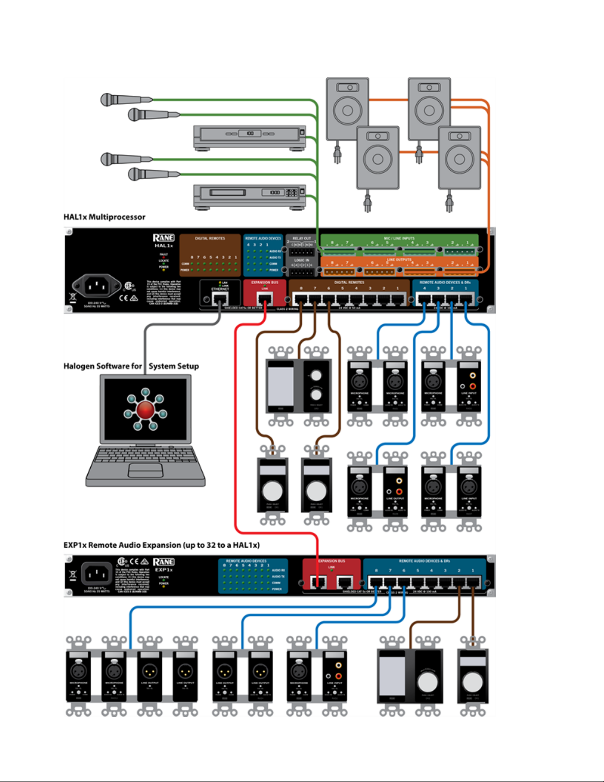
The following graphic provides a visual of an entire HAL1x System:
4
Page 11
CHAPTER 1: Getting Started
5
Page 12
HAL SYSTEM INSTALL GUIDE
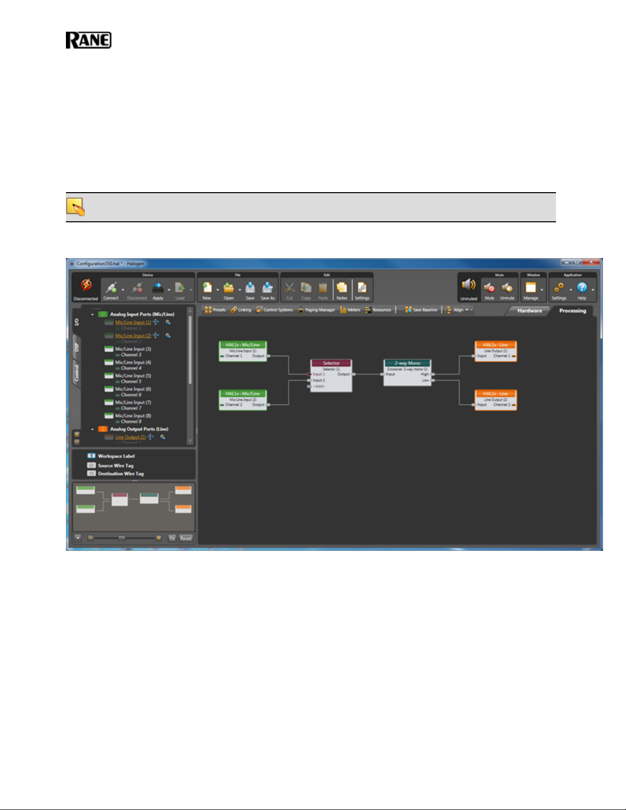
Software Component
Included in the HAL System is a software application, called Halogen, that you use to configure and manage the
entire system. Halogen contains two primary graphical workspaces, the Hardware Workspace and the Processing
Workspace, in which you simply drag and drop hardware components and processing blocks to set up the audio
system you want. You can work in online mode (connected to HAL) or offline mode (not connected to HAL or
any other hardware). The ability to work in offline mode makes Halogen a powerful design tool available for use
whether or not you have the hardware in hand. And not only can you design your system without having hardware in place, you can also test your system before you install the hardware! Now that's powerful!
NOTE: When working in online mode, changes made in the software are immediately implemented and saved
to HAL (with the exception of DSP changes that require a system recompile).
Below is a sample of the Halogen Processing Workspace:
For more details on the Halogen software application, see "Introduction to the Halogen Software" on page 87.
6
Page 13

System Requirements
To use a HAL System, the following items are required:
l
You must have access to a computer running Microsoft Windows 7 or greater. The computer must also have
an Ethernet port, which you use to connect the computer to the HAL device (either directly or via an Ethernet network via a shielded CAT5e cable). This connection is necessary for using the Halogen software to
load configuration information into the device and also for monitoring detailed status information. Note that
some status information is visible on the hardware itself.
l
You must have administrative rights to install the Halogen software, but you do not need administrative
rights to run the software.
l
Most RADs require two, three, or four-gang standard switchboxes (for installation into a wall). A DR1
requires a one-gang switchbox, while a DR2 and DR3 require two-gang switchboxes. Switchboxes used for
both RADs and DRs must have a minimum depth of 2 1/4" (57 mm).
Minimum Requirements for Running Halogen
l
Microsoft Windows 7 or greater (32 or 64-bit)
l
PC with 1.6 GHz Dual Core Processor (for example, Intel Core Duo, AMD Athlon X2)
l
1 GB RAM
CHAPTER 1: Getting Started
l
2 GB available hard disk space
l
Display Resolution: 1024x768, 24 bit color
l
Ethernet adapter: 100baseT
l
DVD Drive for installation from DVD (or can install from Rane website)
Recommendations for Best Performance
l
Microsoft Windows 7 or greater (32 or 64-bit)
l
PC with mid-level processor @ 2GHz multi-core or better (for example, Intel i3 or greater)
l
2 GB RAM
l
2 GB available hard disk space
l
Display Resolution: 1920 x 1080, 24-bit color
l
Display Adaptor: supports rendering tier 1 or 2 (see http://msdn.microsoft.com/en-us/library/ms742196.aspx)
(i.e. directX 9.0 or greater)
l
Ethernet adapter: Gigabit
7
Page 14
HAL SYSTEM INSTALL GUIDE
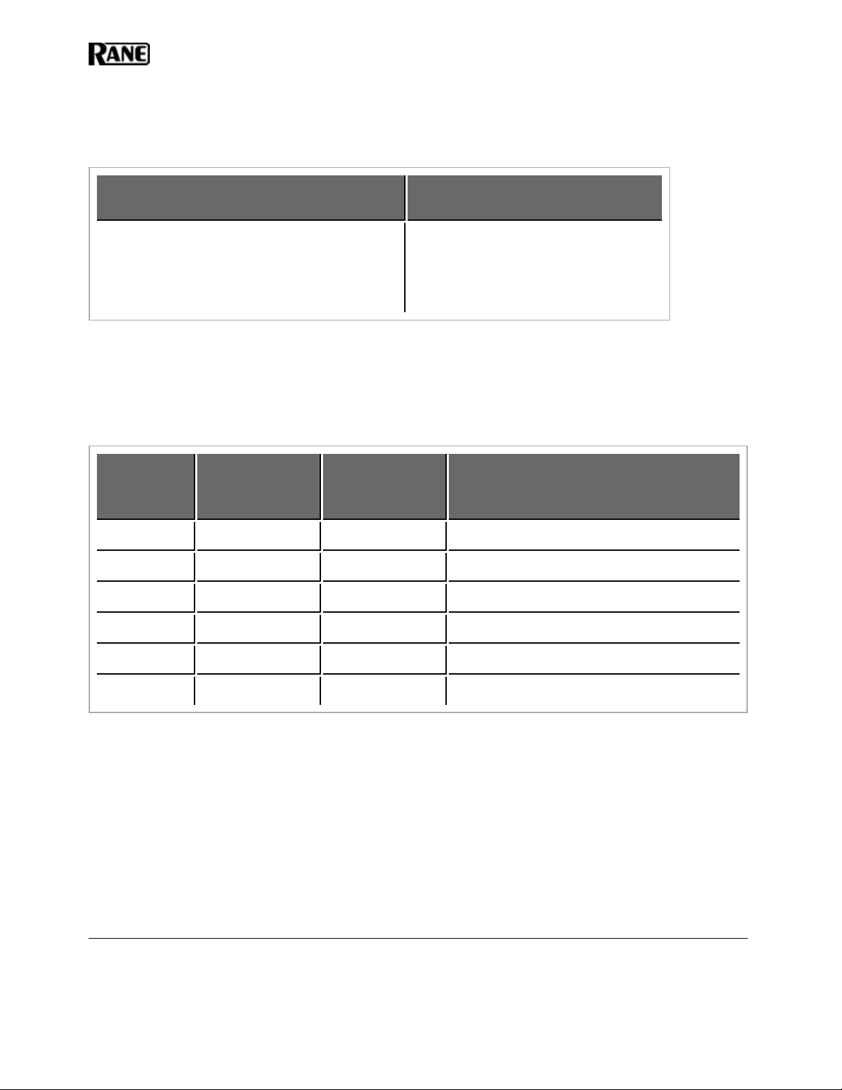
Administrative Rights Requirements
The following table outlines which Halogen tasks require administrative rights and which do not:
Requires administrative rights
l
Installing Halogen
l
Installing software updates to Halogen
l
Manually starting or stopping the RaneLink
Does not require administrative
rights
l
Running and using Halogen
l
Updating the HAL firmware
II service
Required Ports
Communications between the PC(Halogen/RaneLink) and HAL
The PC and HAL exchange information using the following ports and protocols:
Local Port
(PC)
Any 22 TCP Secure file transfer
4992 Any TCP Meter control
Remote Port
Protocol Purpose
(HAL)
4993 Any TCP Configuration
4994 Any UDP Discovery broadcast
4994 Any TCP RaneLink II
1
4995 Any TCP Meter data
These ports are listed from the PC's perspective to aid in configuring the PC's firewall so that RaneLink and Halogen can communicate with HALhosts on your network.
HAL devices send occasional UDP broadcast messages. The RaneLink II service on the PC listens constantly for
these messages and when it receives one, it does three things, if necessary:
l
Sets up a temporary link-local IP address (in other words, the address is cleared when the computer reboots)
on the appropriate network interface card (NIC).
l
Adds an entry to the computer's network route table. RaneLink II maintains the list of HAL devices and it
must be running for Halogen to communicate with a HAL, even if the HAL has been located by a manual
search.
l
Opens and maintains a TCP connection with HAL so that it can receive status updates.
1
A service needed by Halogen to establish a connection with HAL.
8
Page 15

CHAPTER 1: Getting Started
Additional Ethernet Communications
Halogen and HAL also use the following ports and protocols (independently of each other) to communicate with
other systems such as a DHCPserver or external control systems:
Local Port
Remote Port Protocol Purpose
(PC or HAL)
68 67 UDP DHCP Client
4996 Any TCP External Control systems
80 (HAL)
8880 (PC)
Any TCP Web Controls web server
Required Processes
The following processes are required for working with the HALSystem and for establishing a connection between
Halogen and HAL.
Process Purpose Location
Halogen.exe‡
hal1.pcops.exe‡
Use to design your entire audio
system and connect to your HAL
device.
Simulates the behavior of a HAL
when Halogen is not connected to
a HAL. Allows for testing of such
things as control links and presets,
even when not connected to a
HAL.
C:\Program Files (x86)\Rane Corporation\Halogen\Halogen.exe
C:\Program Files (x86)\Rane Corporation\Halogen\hal1.pcops.exe
The server for web controls when
python.exe‡
RaneLink II
‡If running 32-bit Windows, you can find Halogen.exe, hal1.pcops.exe, and python.exe in the "Program Files"
directory.
Halogen is not connected to a
HAL.
A service needed by Halogen to
establish a connection with HAL.
C:\Program Files (x86)\Rane Corporation\Halogen\web\python.exe
Services ControlPanel
9
Page 16

HAL SYSTEM INSTALL GUIDE
Using the HAL System Documentation
A variety of documentation is available to help you get started with and use your HALSystem:
Halogen Help System
A comprehensive help system is installed with the Halogen software. It contains all the information you need
to work with the system. There are several ways to access the Help System:
l
Click the Help icon on the application toolbar: Clicking the icon itself opens the Help System.
Clicking the down arrow displays a list of options including such things as access to the Rane website, checking for updates to the Halogen software, and sending an email to Rane.
l
Click the Help icon that appears in the upper right corner of Halogen dialog boxes. Clicking this
icon opens the Help topic related to the specific dialog box. From there you can access the entire Help
System, if needed.
l
Right-click on different elements in the user interface. A Help option appears in the context menu.
Click this option to open the relevant Help topic. Pressing F1 when an area of the user interface has
focus also displays its relevant Help topic.
l
To search for information within the Help System, you can use the tabs on the Help Viewer's left pane
to search the index (click the Index tab) or perform a full-text search (click the Search tab). You can
also use the Quick search box in the Help System toolbar to search for text within the currently displayed topic:
HAL System Design Guide
This guide is offered as a PDF file and contains a product overview, details about the HAL System's key features, and best practices for designing a HAL audio system. Note that the information in this guide is also
available in the Halogen Help System. You can find this guide on the Rane website (http://rane.com/hal) as
well as on the product DVD.
HAL System Installation Guide
This guide is offered as a PDF file and includes step-by-step instructions on installing the HALhardware,
loading a configuration, and testing the system. This information is also included in the Halogen Help System. You can find this guide on the Rane website (http://rane.com/hal) as well as on the product DVD.
AMXControl Systems Guide
This guide, includes an introduction to using external control systems with HAL. It also discusses an example HAL1 configuration and how to set up an AMX controller and touch panel to communicate with a Halogen/HAL Control Server. In addition, an appendix is included with reference information on the
HALexternal control message protocol and how to use a telnet client to monitor and troubleshoot the operation of a control system at the message protocol level.
The guide is designed to be used in conjunction with the files found in the AMX Support Package. The contents of this support package include:
l
AMXControlSystems_Guide.pdf - The AMX Guide pdf file
l
ControlSystemSample.hal - Halogen configuration file intended for loading in Halogen or your
HAL1x
l
Rane_HAL.apw - NetLinx Studio program project file
l
Main.axs - NetLinx program source file
l
Rane_HAL_TP.TP4 - TPDesign4 touch panel project file
10
Page 17

CHAPTER 1: Getting Started
The AMX Support Package is installed with the Halogen software and can be accessed from the Windows
Start Menu under Halogen ->Guides. If you want to access the files directly they are available on the product DVD or from the Halogen install directory:
l
C:\Program Files (x86)\Rane Corporation\Halogen\Guides\Support Packages\AMX directory
You can also download the most up-to-date version of this support package from the Rane website
(http://rane.com/hal).
Crestron Control Systems Guide
This guide, includes an introduction to using external control systems with HAL. It also discusses an example HAL1x configuration and how to set up a Crestron controller and virtual touch panel to communicate
with a Halogen/HAL Control Server. In addition, an appendix is included with reference information on the
HALexternal control message protocol and how to use a telnet client to monitor and troubleshoot the operation of a control system at the message protocol level.
The guide is designed to be used in conjunction with the files found in the Crestron Support Package. The
contents of this support package include:
l
CrestronControlSystems_Guide.pdf - The Crestron Guide pdf file
l
ControlSystemSample.hal - Halogen configuration file intended for loading in Halogen or your
HAL1x
l
Rane_HAL.smw - SIMPL Windows program project file
l
Rane_HAL_TP.vtp - VisionTools Pro-e touch panel project file
l
Rane HAL Level Processor.usp - SIMPL+ user module source file
l
Rane HAL Level Processor.ush - Compiled user module
The Crestron Support Package is installed with the Halogen software and can be accessed from the Windows
Start Menu under Halogen ->Guides. If you want to access the files directly they are available on the product DVD or from the Halogen install directory:
l
C:\Program Files (x86)\Rane Corporation\Halogen\Guides\Support Packages\Crestron directory
You can also download the most up-to-date version of this support package from the Rane website
(http://rane.com/hal).
Stardraw Control Systems Guide
This guide, includes an introduction to using external control systems with HAL. It also discusses an example HAL1 configuration and an example Stardraw Control application and driver that communicates with a
Halogen/HAL Control Server. In addition, an appendix is included with reference information on the
HALexternal control message protocol and how to use a telnet client to monitor and troubleshoot the operation of a control system at the message protocol level.
The guide is designed to be used in conjunction with the files found in the Stardraw Control Support Package. The contents of this support package include:
l
StardrawControlSystems_Guide.pdf - The Stardraw Control Guide pdf file
l
ControlSystemSample.hal - Halogen configuration file intended for loading in Halogen or your
HAL1x
l
HAL1 Stardraw Example Project.s03 - Stardraw Control Project
l
HAL1 Example Driver.cs - Stardraw HAL1 driver source code. This is part of the Stardraw Control
Project but is included separately here for reference.
11
Page 18

HAL SYSTEM INSTALL GUIDE
The Stardraw Control Support Package is installed with the Halogen software and can be accessed from the
Windows Start Menu under Halogen ->Guides. If you want to access the files directly they are available on
the product DVD or from the Halogen install directory:
l
C:\Program Files (x86)\Rane Corporation\Halogen\Guides\Support Packages\Stardraw Control directory
You can also download the most up-to-date version of this support package from the Rane website
(http://rane.com/hal).
12
Page 19

CHAPTER 2: Hardware Component Details
This chapter provides details about the HALSystem hardware devices that you'll be installing.
Overview of HAL Devices
The HAL host device (which is referred to as HAL throughout this guide) is the brain that controls the entire
HALSystem. It can connect to a variety of other hardware (or slave devices) such as analog equipment, RADs,
DRs, and EXPs. Inside the HAL hardware is a DSP audio processing engine and a host controller that controls
DSP operations and manages control links, presets, and more. There is only one HAL device per system. You cannot connect one HAL to another.
NOTE FOR DRAG NET USERS: The DSP processing engine in the HAL1 device is four times more powerful
than the RPM88, the HAL2 has twice the power as the RPM88, and the HAL3, HAL3s, and HAL4 have
the same amount of DSP processing power as the RPM88.
Other Functionality
In addition to hosting other hardware devices and managing system operations, HAL also does the following:
l
Provides power to connected RADs, and DRs
l
Stores configuration settings and compatible firmware for itself and for each connected RAD, DR, and EXP
l
Provides a connection to an Ethernet network (for control of HAL and the connected devices)
l
Displays various status indicators (LEDs) providing information about the health of the system
Available HAL Models
The following HAL models are currently available. For the most current list of HAL models, see the Rane website.
HAL1x
The device connections that are possible on a HAL1x are as follows:
l
4 Remote Audio Devices (RADs)
l
8 Digital Remotes (DRs)—Can add up to 4 more by plugging them into the RAD ports
l
1–32 Expansion Unit Devices (EXPs) (CAT 5e Expansion Bus)
l
8 Mic/Line Inputs
l
8 Line Outputs
l
4 Logic Inputs
l
2 Relay Outputs
HAL2
The device connections that are possible on a HAL2 are as follows:
l
4 Remote Audio Devices (RADs)
l
4 Digital Remotes (DRs)—Can add up to 4 more by plugging them into the RAD ports
13
Page 20
HAL SYSTEM INSTALL GUIDE
l
4 IR Remotes
l
8 Mic/Line Inputs
l
8 Line Outputs
l
1 AES3 Stereo Input
l
1 AES3 Stereo Output
l
4 Logic Inputs
l
2 Relay Outputs
HAL3s
The device connections that are possible on a HAL3s are as follows:
l
2 Remote Audio Devices (RADs)
l
2 Digital Remotes (DRs)—Can add up to 2 more by plugging them into the RAD ports
l
2 Mic/Line-Plus Inputs
l
6 Line Outputs
l
4 Logic Inputs
HAL4
The device connections that are possible on a HAL4 are as follows:
l
1 Digital Remote (DR)
l
2 Mic/Line-Plus Inputs
l
2 Line Outputs
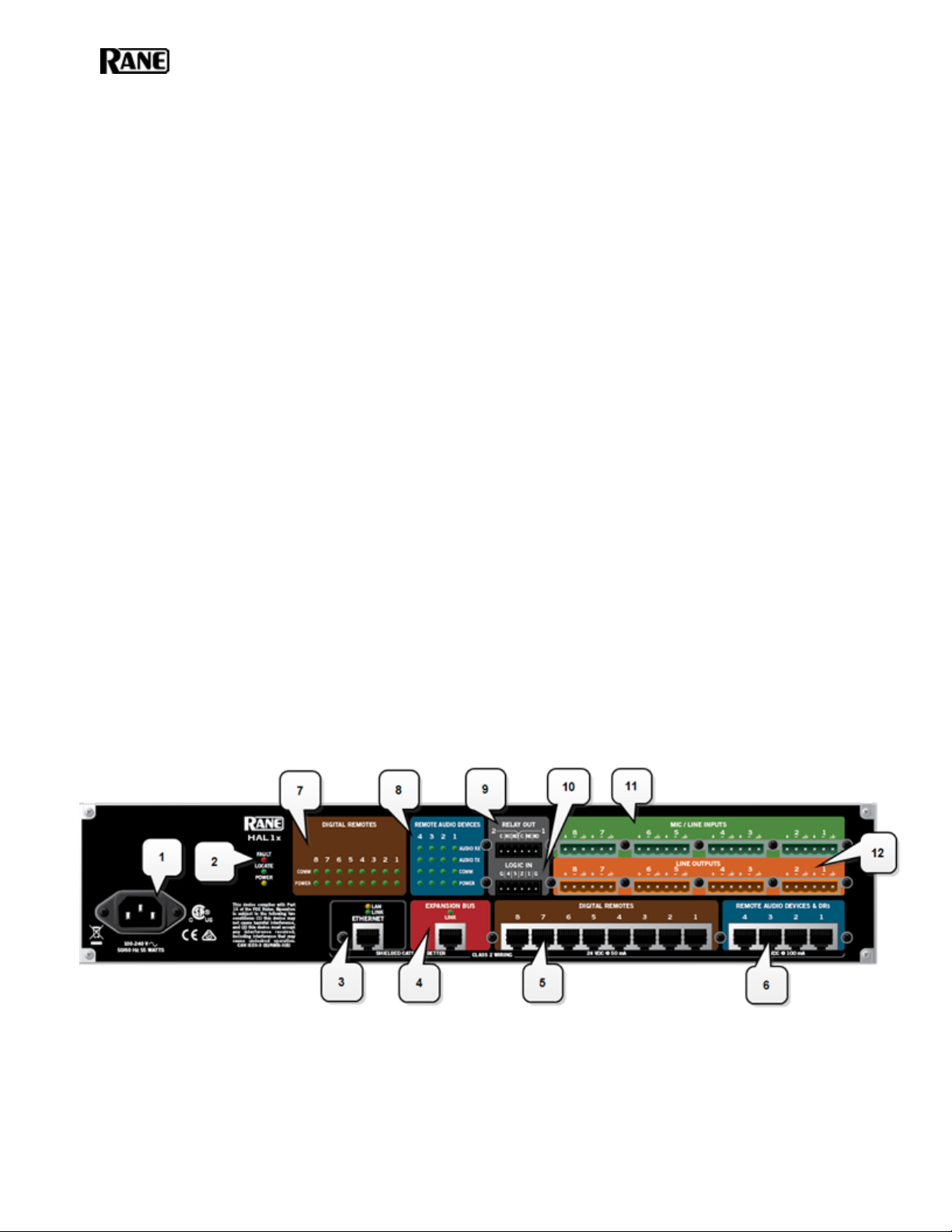
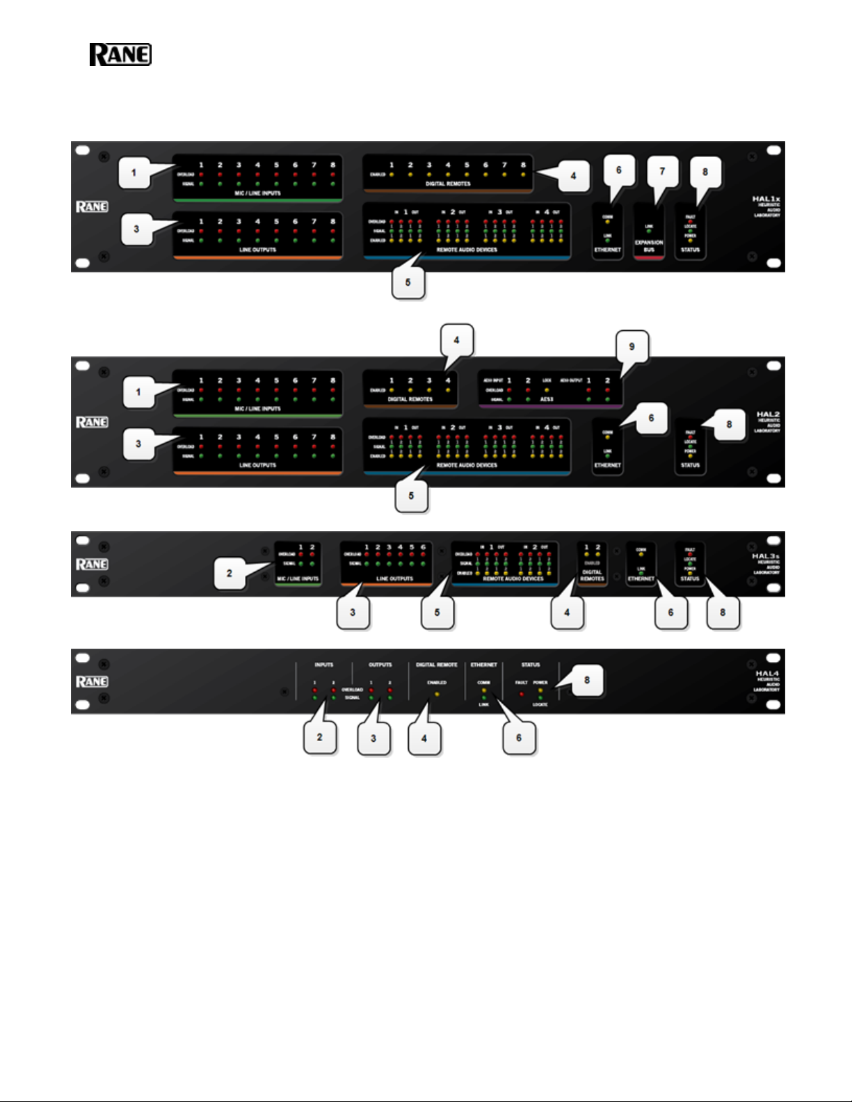
HAL Front and Rear Panels
This section includes front and rear panel graphics for all current HAL models and descriptions for each major area
on the panels.
Rear Panel Description
14
Page 21
CHAPTER 2: Hardware Component Details
1. The Power IEC jack connects to AC line voltage, 100-240 VAC, 50/60 Hz.
2. Fault, Locate, and Power LEDs
The Fault LED (red) turns on when something in the hardware goes awry. The first step in troubleshooting the problem is to open the Halogen software and check the status of this HAL device.
The Locate LED flashes green when you place this HAL device in Locate Mode (via the Halogen software). The purpose of this Locate functionality is for verification, when working in the software, of the
physical device you are configuring or viewing.
The Power LED lights when the HAL hardware is powered on.
3. Ethernet port and LAN and Link LEDs
Use this port to connect HAL to an Ethernet switch or directly to a computer.
15
Page 22

HAL SYSTEM INSTALL GUIDE
NOTE: This Ethernet port contains auto-MDIX functionality, which means that you can use either a
standard Ethernet cable or a crossover cable to connect to a computer or Ethernet switch. The autoMDIX functionality takes care of coordinating the proper connection between the devices.
The Ethernet LAN LED flashes when HAL detects any Ethernet packets on the network. The Link LED
indicates if the Ethernet network is connected. If HAL is connected to an Ethernet network but the Link
LED is off, there is likely a problem with the connection.
4. Expansion Bus LED and CAT5e port
Use the Expansion Bus port to connect an Expansion Bus device (such as an EXP1x) to the HAL via a
shielded CAT 5e cable. To attach additional Expansion Bus devices to your HAL System, use a shielded
CAT 5e cable to connect each new device to the previous device—in a daisy chain style.
If lit, the Expansion Bus Link LED indicates that the Expansion Bus device is communicating properly
with HAL. If an Expansion Bus device is properly connected to the port yet the status LED remains dark,
there is likely a problem with the connection.
5. Digital Remote Device ports
Use these ports to connect each DR to the HAL via a standard shielded CAT 5e (or better)cable. You
must use a shielded Ethernet cable for this connection. If you need more DR connections than the number
of DR ports that the HAL provides, you can use a RAD port to connect a DR.
6. Remote Audio Device ports
Use these ports to connect each RAD to the HAL via a standard shielded CAT 5e (or better)cable. You
must use a shielded Ethernet cable for this connection. If you need more RAD connections, you will need
to connect an Expansion Unit with RAD ports (such as an EXP1) to your HAL device. You cannot connect a RAD to a DR port.
7. Digital Remote Device LEDs
Provides information about the health of the shielded CAT 5e connection between each DR and HAL.
The numbers correspond to the DR ports in the lower area of the rear panel. The Comm LED (on the top
row) lights solidly if the DR's data communications pair is working properly. The Power LED (on the bottom row) lights solidly if HAL is supplying adequate power to the DR port.
8. Remote Audio Device LEDs
Provides status information about the health of the shielded CAT 5e connection between each RAD and
HAL. The numbers correspond to the RAD ports in the lower right corner of the rear panel. For example,
the LEDs for number 1 provide information about the RAD connected on port 1. Each LED corresponds
with one twisted pair within the shielded CAT 5e cable. If the twisted pair is functioning properly, the
LED displays a solid green light when the HAL is programmed to expect the RAD model that is physically plugged in. When all cable pairs are working properly, but HAL is not yet programmed for the connected RAD model, all four LEDs flash red. Note that flashing red is a good thing: the cable’s good – just
program HAL and you’re done.
l
Audio Rx LED—lights solidly if the HAL receive pair is working properly.
l
Audio Tx LED—lights solidly if the HAL transmit pair is working properly.
l
Comm LED—lights solidly if the RAD's data communications pair is working properly.
l
Power LED—lights solidly if HAL is supplying adequate power to the RAD port.
16
Page 23

CHAPTER 2: Hardware Component Details
NOTE: The Remote Audio Device LEDs on the front panel differ from those on the rear panel. The
front panel LEDs provide information about signal activity on each audio channel. See the "Overview of HAL Devices" on page 13 for more details.
TIP: You can use the Remote Audio Device LEDs on the rear panel and on the RAD to trou-
bleshoot connection problems. See "Troubleshooting the HAL Hardware" on page 101 and "Troubleshooting RAD Devices" on page 103 for details.
9. Relay Out ports
Reed relay ports used to signal another device. A common implementation is to link a relay port to a Toggle control so that an end user can change its value. Also, the Halogen software contains a checkbox for
each relay port, the value of which you can include in a preset or link to another control, making it possible to use a preset or control to turn the relay port on or off.
10. Logic In ports
Use these TTL 5-volt digital logic input ports to communicate to the HAL System via an external control
device. You can configure each Logic In port to control a selector, toggle, or command within the HAL
System. For example, you might use a Logic In port to select between two audio channels, or to mute the
whole system.
11. Mic/Line Input ports
Use these ports to connect analog microphones or line input devices. Note that the Mic In ports support
phantom power.
12. Line Output ports
Use these ports to connect analog line output devices, such as amplifiers or powered speakers.
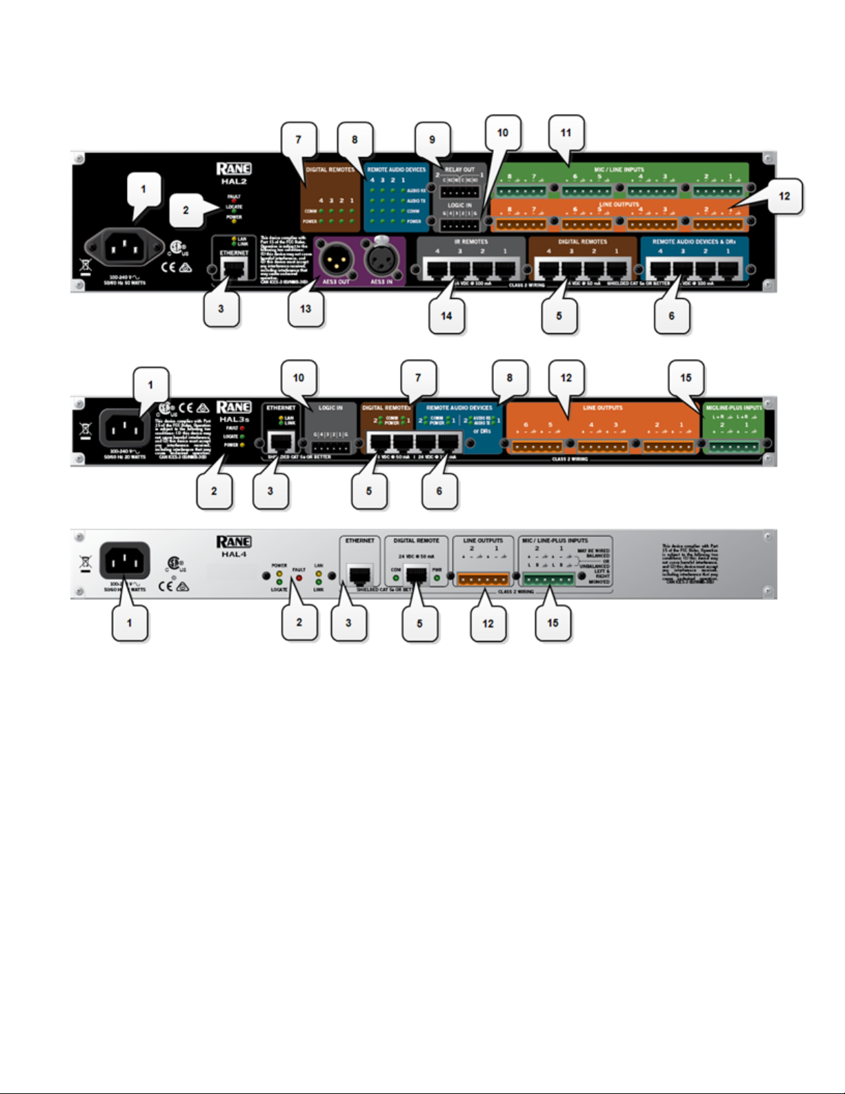
13. AES3 ports
Use these ports to connect AES3 inputs and outputs to the HAL. The HAL2 supports one input port and
one output port using standard XLR connectors. Each AES3 port provides two digital audio channels.
14. IRRemote ports
Use these ports to connect each IR Remote to the HAL via a standard shielded CAT 5e cable. You must
use a standard Ethernet cable for this connection.
15. Mic/Line-Plus Input ports
Use these ports to connect microphone, balanced or unbalanced line input devices. When configured in
Halogen for Condenser Mic, each input provides +48 V phantom power and 18 dB input gain. When Configured for Dynamic Mic, each input provides 30 dB input gain. When configured in Halogen for balanced, each input is +4 dBu balanced. When configured for unbalanced, each input is -10 dBV
unbalanced, with left and right channels summed to a single mono input.
17
Page 24
HAL SYSTEM INSTALL GUIDE
Front Panel Description
1. Mic/Line Input LEDs
Provides status information about mic/line analog inputs connected to the HAL. The numbers correspond
to the mic/line input ports on the rear panel.
These LEDs provide information on the following:
l
Overload LED (red) – indicates that the mic/line input is experiencing a signal overload
l
Signal LED (green) – indicates the presence of an audio signal on the mic/line input
2. Mic/Line-Plus Input LEDs
18
Page 25

CHAPTER 2: Hardware Component Details
Provides status information about mic/line-plus analog inputs connected to the HAL. The numbers correspond to the mic/line-plus input ports on the rear panel.
These LEDs provide information on the following:
l
Overload LED (red) – indicates that the mic/line-plus input is experiencing a signal overload
l
Signal LED (green) – indicates the presence of an audio signal on the mic/line-plus input
3. Line Output LEDs
Provides information about HAL analog outputs. The numbers correspond to the line output ports on the
rear panel.
These LEDs provide information on the following:
l
Overload LED (red) – indicates that the line output is experiencing a signal overload
l
Signal LED (green) – indicates the presence of an audio signal on the line output
4. Digital Remote LEDs
Indicates which Digital Remotes are enabled. Each numbered LED corresponds to the Digital Remote port
with the same number. If a Digital Remote is connected on a port but its Enabled LED is off, there is
likely a problem with the shielded CAT 5e connection or with the Digital Remote itself. If an Enabled
LED is flashing, it indicates that the physical Digital Remote model does not match the Digital Remote
model specified for this port in the HAL configuration.
5. Remote Audio Ports status indicators
Provides information about the RAD audio channels. The numbers at the top of the front panel correspond
to the RAD ports on the back of the HAL. For example, the LEDs for number 1 provide information
about the RAD connected on port 1.
Under each RAD number are LEDs for four audio channels, two input and two output. These four LEDs
represent the maximum number of channels a RAD is capable of transporting. However, not all RAD models use all four channels. For example, the RAD1 model provides two microphone inputs, so only the two
columns of indicators labeled IN would be active.
These LEDs provide information on the following:
l
Overload LED (red)–indicates that the channel is experiencing a signal overload
l
Signal LED (green)–indicates the presence of an audio signal on this channel
l
Enabled LED (yellow)–indicates the availability of the associated audio channel. If a RAD is connected on this port and all Enabled lights are off, this indicates a problem with the shielded CAT
5e connection or with the RAD. If the Enabled LEDs are flashing, this indicates that the physical
RAD model does not match the RAD model specified for this port in the HAL configuration.
6. The Ethernet Comm and Link LEDs
Provides status information about the HAL Ethernet connection.
l
Comm LED (yellow) – flashes when HAL has been discovered by at least one PC running RaneLink II1, is solid when Halogen is exclusively connected to HAL, is off when HALhas yet to be
discovered.
1
A service needed by Halogen to establish a connection with HAL.
19
Page 26

HAL SYSTEM INSTALL GUIDE
l
Link LED (green) – indicates if the Ethernet network is connected. If the HAL is connected to an
Ethernet network but the Link LED is off, this indicates a problem with the connection.
7. The Expansion Bus LED
If lit, indicates that an Expansion Bus device is properly connected to the HAL. If an Expansion Bus
device is properly connected to the port and powered on yet the status LED remains dark, there is likely a
problem with the connection.
8. Fault, Locate, and Power LEDs
The Fault LED (red) turns on when something in the hardware goes awry. The first step in troubleshooting the problem is to open the Halogen software and check the status of this HAL device.
The Locate LED flashes green when you place this HAL device in Locate Mode (via the Halogen software). The purpose of this Locate functionality is for verification, when working in the software, of the
physical device you are configuring or viewing.
The Power LED lights when the HAL hardware is powered on.
9. AES3 LEDs
Provides information about the AES3 digital audio channels. The numbers at the top of the front panel correspond to the AES channels on each port, two for the input port and two for the output port.
The Lock LED (yellow) indicates when the AES3 input port is locked to the attached AES3 output
device.
Under each AES3 channel number are LEDs for that channel's audio, providing information on the following:
l
Overload LED (red)–indicates that the channel is experiencing a signal overload
l
Signal LED (green)–indicates the presence of an audio signal on this channel
Discontinued HAL Models
This section describes HAL models that are no longer in production. For the most current list of HAL models, see
the Rane website. Data Sheets for discontinued models may also be downloaded from the Rane website.
The following devices are no longer available: HAL1, EXP1, and HAL3.
While Rane no longer produces the HAL3, Halogen software continues to provide support for this product, allowing customers to:
l
Connect to HAL3 devices
l
Open existing HAL3 configurations
l
Build new HAL3 configurations
To build a new HAL configuration with a discontinued HAL, see Creating Configurations with Discontinued
HAL devices below.
NOTE: Halogen no longer supports the HAL1 and EXP1 devices. If you would like to create or update a
HAL1 configuration, use Halogen version 4.1.1 or earlier. To run multiple versions of Halogen on your PC,
see http://blog.rane.com/2013/01/15/tip-running-multiple-versions-of-halogen-on-one-computer/.
20
Page 27

CHAPTER 2: Hardware Component Details
HAL1 (Replaced by HAL1x)
The HAL1 uses a daisy-chain FireWire expansion bus able to support up to four EXP1 devices with a total of 32
output channels and 64 input channels. The maximum cable length for FireWire is 14.8 feet (4.5 meters).
For more information about the HAL1 FireWire expansion bus and EXP1 expansion unit, see "Overview of HAL1
Expansion Unit (Discontinued)" on page 1.
The HAL1x expansion bus uses a proprietary protocol running on a gigabit Ethernet physical layer with expansion
devices connected in a daisy-chain configuration as before. The new expansion bus supports 512 output channels
and 512 input channels with a maximum cable length of 330 feet (100 meters). There are currently four expansion
devices for the HAL1x: EXP1x, EXP3x, EXP5x and EXP7x. The new bus is a significant improvement over the
original FireWire bus.
For more information about the HAL1x expansion bus and expansion units, see "HAL1x Expansion Units" on
page 64.
You cannot use the new (x) version expansion devices with the discontinued HAL1. The new HAL1x requires (x)
version expansion devices.
The device connections that are possible on a HAL1 are as follows:
l
4 Remote Audio Devices (RADs)
l
8 Digital Remotes (DRs)—Can add up to 4 more by plugging them into the RAD ports
l
1–4 Expansion Unit Devices (EXP1 devices) (FireWire Expansion Bus)
l
8 Mic/Line Inputs
l
8 Line Outputs
l
4 Logic Inputs
l
2 Relay Outputs
HAL3 (Replaced by HAL3s)
The original HAL3 provides two line/line+ inputs, one RAD port and three DR ports.
The new HAL3s provides two Mic/Line/Line+ inputs with available 48 volt phantom power, two RAD ports and
two DR ports. The HAL3s also improves line input dynamic range by about 10 dB. The new features of the
HAL3s open up new application spaces for the product, by supporting microphone input, two additional outputs
and two additional inputs via the additional RAD port.
The device connections that are possible on a HAL3 are as follows:
l
1 Remote Audio Device (RAD)
l
3 Digital Remotes (DRs)—Can add up to 1 more by plugging it into the RAD port
l
2 Line-Plus Inputs
l
6 Line Outputs
l
4 Logic Inputs
Creating Configurations with Discontinued HAL devices
By default, Halogen only shows HALs currently in production in the New configuration drop down list.
21
Page 28
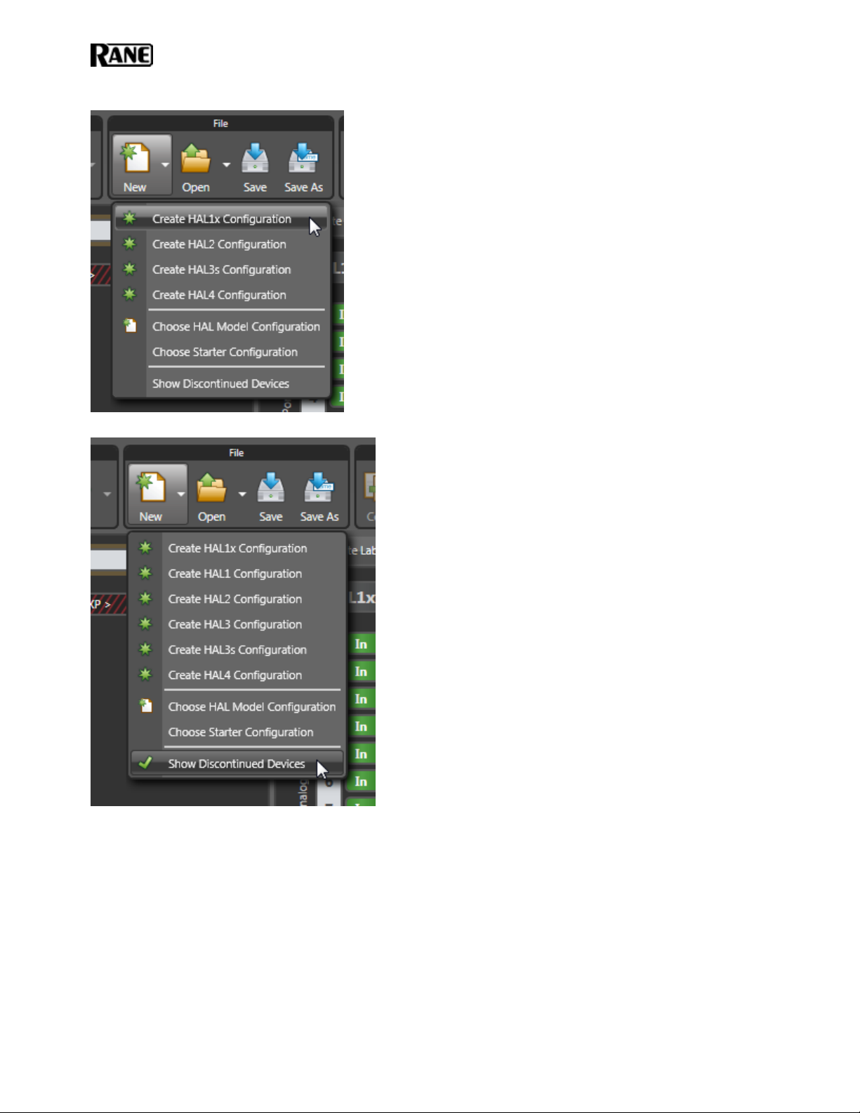
HAL SYSTEM INSTALL GUIDE
Click on Show Discontinued Devices to add discontinued HAL devices to the list as shown below:
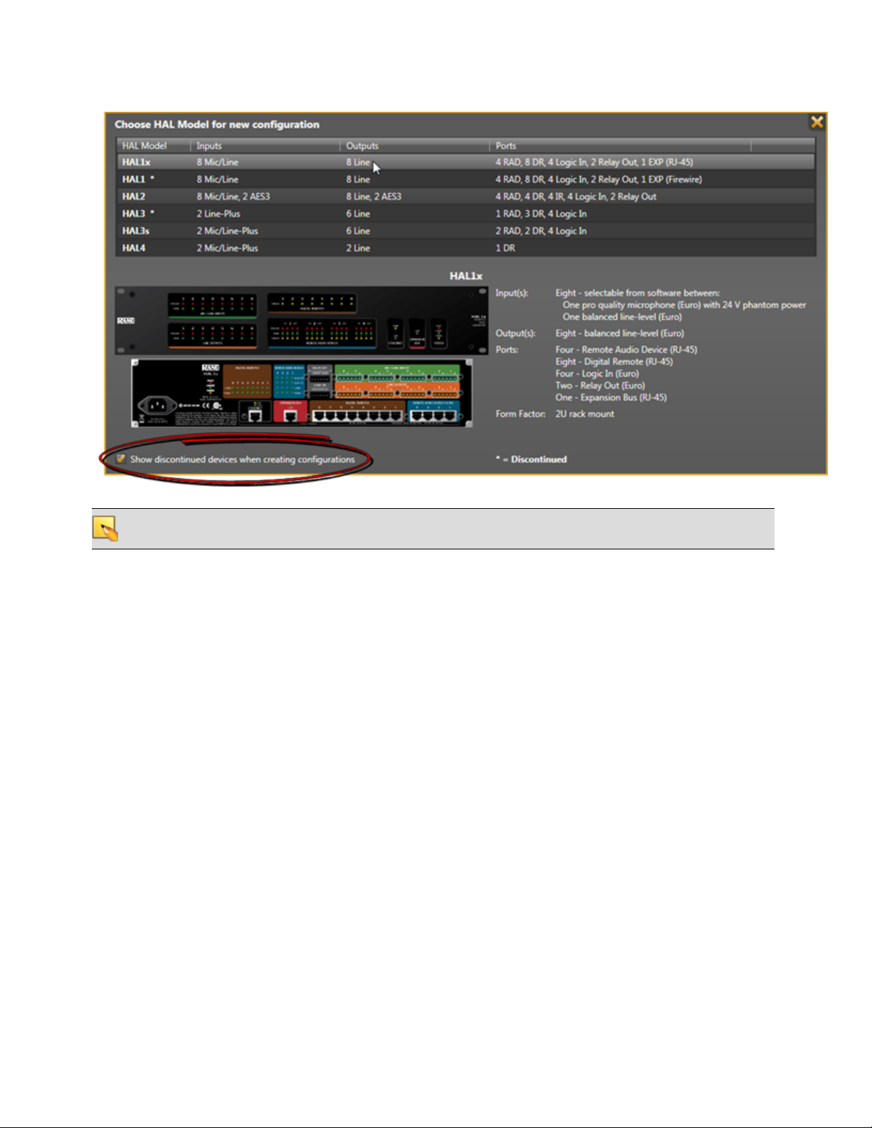
If you click on the New menu button, Halogen opens the HALModel Picker dialog box. To display discontinued
models, check the Show discontinued devices when creating configurations checkbox:
22
Page 29
CHAPTER 2: Hardware Component Details
NOTE: In Halogen version 5.0.1 and later, you cannot create a new configuration for the unsupported HAL1
device.
Remote Audio Devices
The primary purpose of a Remote Audio Device (RAD) is to amplify, digitize, and transmit a digital audio signal
via shielded CAT 5e cable to a HAL host device. RADs can also receive a digital signal from the HAL and then
convert it to analog before sending it to its attached audio equipment. RADs are capable of transmitting and receiving up to four channels of digital audio (two in each direction). To better fit your needs, however, Rane offers various RAD models. Most RAD models are designed to fit in a standard U.S. two, three, or four gang switchbox.
The HAL System offers a variety of RAD models, each of which serves a unique purpose. For example, a RAD1
contains two microphone input channels. When you design an audio system, you choose the RAD models that are
appropriate for your application. You must then provide configuration information to HAL so that it knows which
RAD models to expect on each port and what information to send to each RAD. For more information, see "Available RADModels" in the Halogen Help System. You can also read about the available RAD models on the Rane
website.
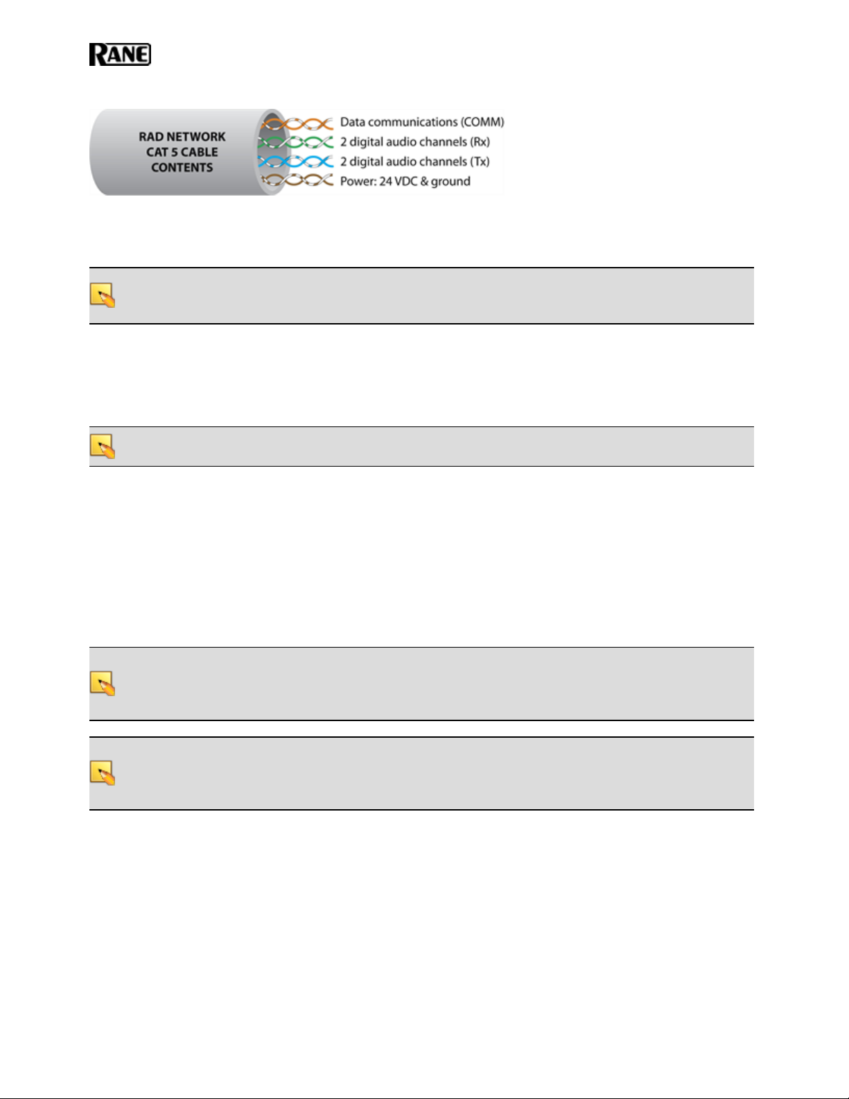
How the shielded CAT 5e Cabling is Utilized
The shielded CAT 5e cable that connects the RAD to HAL also provides power to the RAD as well as a path for
data communications. Data communications makes it possible to control the RAD’s configuration settings, view
status information, and update a RAD’s firmware – all from the host HAL device. The following picture illustrates
how the four twisted pairs within the shielded CAT 5e cable are utilized.
23
Page 30
HAL SYSTEM INSTALL GUIDE
l
The orange pair is reserved for data communications between the RAD and HAL. Data communications is
needed for such things as sending configuration information from HAL to the RAD, sending firmware
updates from HAL to the RAD, and sending status information from the RAD to HAL.
NOTE: Configuration information for a specific RAD (for example, LED intensity, microphone sensitivity,
and RAD and channel names) is stored in the HAL device, not in the RAD. This makes it easy to swap in a
new RAD, if necessary, without losing configuration data.
l
The green and blue pairs carry two channels each of balanced, differential, digital audio. Tx refers to audio
that the RAD sends to the HAL. Rx refers to audio that the RAD receives from HAL.
l
The brown pair provides 24 VDC power and ground for the RAD. This is (obviously) the wire you should
check if it appears a RAD is not receiving power.
NOTE: Digital Remotes (discussed on page 43) use only the orange pair (for data communications) and the
brown pair (for power).
RADGrounding
Careful grounding of RADs is important for optimum performance. Except for the DR4, all RADs and DRs are
powered from the +24 VDC & Ground twisted pair located within the shielded CAT 5e (or better) cable connecting them to the HAL system of multiprocessors. The exposed metal of all RADs and DRs is connected to the
ground conductor inside the cable and to the cable shield when properly terminated. The shield conductor and the
ground twist are in parallel and are connected together at both cable ends. Except for the RAD16z, this in turn connects the HAL/audio equipment rack grounding point and the metal (if used) junction box mounting the RADs
and DRs.
NOTE: For some electrical systems (e.g., isolated grounding systems - sometimes called a single point or star
ground) the grounding procedure outlined above may short two fingers of the building ground system. If this
creates a problem, then use of non-conductive junction boxes, or insulating mounting methods are recommended (or very much required!).
NOTE: The RAD16z is grounded differently than the above. The RAD16z galvanicaly isolates its RJ-45 jack,
cable shield and grounded twist, and the HAL/equipment room ground from its logic and audio I/O grounds.
This means no special ground is needed. This provides 500-volts galvanic isolation as well as standard Eth-
24
Page 31

CHAPTER 2: Hardware Component Details
ernet-like electrostatic protection as the RAD16z cables get hot plugged and unplugged.
25
Page 32

HAL SYSTEM INSTALL GUIDE
The Parts of a RAD
Following is an illustration of the front of a typical RAD, accompanied by descriptions of the RAD’s various hardware features:
1. Label: a location on the RAD for inserting a custom label. One possible use of this label is to identify the
channel number associated with the corresponding jack.
2. XLR Tab: push tab for releasing a microphone cable. If you do not need this tab, you should remove it
before installing the RAD. For more information, see the RAD installation instructions beginning on page
78.
3. Input/Output jacks: the actual jacks to which you connect the appropriate audio device(s). The jacks
differ based on the RAD model.
4. Sig/OL LED: displays a green light when an audio signal is detected, displays a red light when the channel is experiencing a signal overload.
5. Power LED: displays a solid green when the RAD is receiving power, displays solid red if the voltage
received is lower than expected.
6. Comm LED: displays a solid green when the RAD detects two things—the communication pair of wires
and that communication is established between the HAL and RAD. The light displays solid red if the
RAD cannot communicate with the HAL. This is likely due to a problem with the communications pair
of wires.
7. Audio Rx LED: displays solid green when the RAD detects that the pair of wires for receiving audio is
functioning properly, regardless of the RAD model. Displays red if there is a problem.
8. Audio Tx LED: displays solid green if communication with the HAL has been established and the HAL
informs the RAD of the Tx Audio lock. Displays solid red if there is a problem communicating with the
RAD or if there is a problem with the Audio Tx pair of wires.
9. Light sensor: detects the amount of light in the room and dims or brightens all LEDs appropriately—primarily to prevent the LEDs from glowing in a darkened room like cat eyes on Halloween. Note that you
cannot turn these LEDs off manually. This is by design. We wanted to avoid the possibility of someone
erroneously thinking the RAD is defective (because the power light is off) and attempting to replace it
unnecessarily.
26
Page 33

CHAPTER 2: Hardware Component Details
10. Locate mode: The Halogen software application contains a feature allowing you to verify the physical
location of a specific RAD or HAL device. When you place a RAD in Locate mode, the Power, Comm,
Audio Tx, and Audio Rx LEDs on the front of the corresponding RAD flash green. The flashing continues until you cancel the request in the software, place another RAD in Locate mode, interrupt the connection between the computer and the HAL, disconnect the RAD, or power cycle the HAL. Mismatch
mode: When a RAD is connected to a RAD port on the back of a HAL, a comparison is made between
the physical RAD model and the RAD model specified for this port in the HAL configuration. If there is
a mismatch the Power, Comm, Audio Tx, and Audio Rx LEDs on the front of the corresponding RAD
flash red.
Following is an illustration of the back and side of a typical RAD:
WARNING! As it is poor design to plug two microphones into a single microphone input, we do not rec-
ommend this practice. If, however, you have a situation that warrants it, proceed with caution. We recognize
that paralleling microphone jacks can lower the cost of your audio system.
NOTE: RADs are hot-swappable. In other words, you can replace a RAD without having to power down the
system. The HAL automatically detects the new RAD and configures it using the configuration data stored
in the HAL. If the configured RAD and the physical RAD do not match, the HALfront panel Enabled LEDs
for this RAD flash yellow. At the same time, the RAD's Power, Comm, Audio Rx, and Audio Tx LEDs flash
red.
27
Page 34

HAL SYSTEM INSTALL GUIDE
PAGER1 RAD
Setting up paging in the HALSystem is as easy as adding zones to groups (called Scenarios), and then specifying
the Scenarios into which each paging station can page into. The paging hardware (the Pager1 RAD) then displays
the Scenario options available at that station. The user selects the desired Scenario, waits for the Ready green light
indicating that all zones in that Scenario are ready to hear a message, presses the talk button, and speaks into the
microphone.
The Pager1 hardware, which is automatically discovered by the system when connected to a HAL, is a table-top
RAD that accepts a gooseneck via a locking 3-pin XLR connector for increased security.
The Pager1 also includes the following set of paging controls:
l
A selectable list of available Paging Scenarios
l
Indicators for Busy, Caution, and Ready (referring to the selected Scenario).
l
The Busy indicator lights when zones in the selected scenario are in use by a higher or same priority
page.
l
The Caution indicator lights when zones in the selected scenario are in use by a lower priority page.
l
The Ready indicator lights when all zones in the scenario are free to page into.
l
A talk button
l
Signal and Overload LEDs
1
On the following page is an annotated image of a Pager1 device.
1
One or more paging zones treated as a group for paging purposes. Paging Scenarios are defined and named by the
designer, who then also assigns specific Scenarios to specific Paging Stations. End users always page into Scenarios.
28
Page 35

CHAPTER 2: Hardware Component Details
RAD16z
The RAD16 is a popular device for adding flexible I/O capability to Halogen systems. The new RAD16z adds further flexibility with the following improvements:
l
Two universal Mic/Line/Line-Plus inputs
l
Two logic inputs and two logic outputs
l
Improved audio performance
l
500-volt galvanic isolation from RAD port
l
Same plenum-rated chassis as RAD16
How To Use
The RAD16z covers applications possible with the original RAD16 with significant improvements qualifying it
for even more applications, while still having the same plenum rating as RAD16. Most notably, it covers applications where galvanic isolation, logic I/O and universal Mic/Line/Line-Plus inputs are needed.
The addition of Logic I/O allows a RAD16z to support operations like push-to-talk microphones, preset recall,
lighting and projector screen control. The RAD Port of the device features 500 volt galvanic isolation, a useful
29
Page 36

HAL SYSTEM INSTALL GUIDE
characteristic when bridging between locations with divergent technical grounds, eliminating any need for individual isolation transforms on audio inputs and outputs.
Application Example - Small MeetingRooms
The application shown below represents a small meeting, classroom or distance learning room. Typical uses require
a remote for preset recall, level control and source selection. Pairing a RAD16z and DR6 is an uncomplicated and
capable solution.
30
Page 37

CHAPTER 2: Hardware Component Details
31
Page 38

HAL SYSTEM INSTALL GUIDE
Application Example - Galvanic Isolation
The application shown below represents a HAL system where a RAD16z must connect to audio devices in another
part of the building with a divergent technical ground. This can require galvanic isolation from a HAL host or
individual isolation transformers on analog I/O.
AM1 and AM2 RADs
The Automixer 1 (AM1) is a mixer that expands the available microphone channels as well as line inputs, making
it easy for an inexperienced operator to quickly set up and manage the audio for a small multimedia presentation
involving up to four participants using wired or wireless microphones as well as several additional program
sources (such as a laptop computer or a DVD player).
The Automixer 2 (AM2) is a cascadable mixer that expands into the AM1 or other AM2s and increases the number
of microphones by eight or more, but does not expand line inputs. Both products provide superior audio processing with a simple user interface.
32
Page 39

CHAPTER 2: Hardware Component Details
For more details, see the manuals that accompany the AM1 and AM2. More information on these RADs is also
available in the Halogen Help System.
RAD26 - One RoomRAD
The RAD26 provides support for all of the audio I/O and control required to support a typical small room in a
larger distributed audio system. Spa rooms, meeting rooms, group study rooms, and small conference rooms all
require some set of the following features:
l
Local A/V Line input (iPod, Computer, or DVD/Blu-ray player)
o
Stereo Aux Input (mini-TRS, on front bottom, left)
l
One or two microphone inputs
o
Two Mic/Line/Line-Plus Inputs (Euroblock, on rear)
l
Amplifier outputs for ceiling speakers
o
2X4 watts or 1X8 watts (Euroblock, on rear)
l
Headphone Output
o
Stereo (mini-TRS, on front bottom, right)
l
Level and Source Selection
o
Integrated remote control knobs with LCD (similar, but more capable than the DR3)
l
Logic Input and Logic Output
o
Used for preset recall, projector on/off, projector screen up/down, push -to-talk etc. (Euro block, on
rear)
A wall mount RAD26 provides all the essential elements required for a small room with only one HAL-connected,
shielded CAT 5e or better cable providing audio I/O, control and power.
The RAD26 is an input, output, amplifier and control solution for small rooms within a larger sound system.
Hotels with small meeting rooms and spa rooms require local inputs and control and must also receive paging from
elsewhere in the building. Many offices and campuses provide meeting and conference rooms for small groups
which must support in-room A/V presentations but also receive emergency pages and announcements.
33
Page 40

HAL SYSTEM INSTALL GUIDE
Key Features
l
Connects to any Halogen system RAD port via an RPI power injector (included)
l
Audio and Logic I/O are galvanically isolated from the RAD port
34
Page 41

CHAPTER 2: Hardware Component Details
l
Flexible Inputs
o
Two universal Mic/Line/Line-Plus Inputs
n
Rear panel Euro connectors
n
Configure for: Dynamic Mic, Condenser Mic with 24 V phantom power, Unbalanced L+R
Mono or Balanced Line
o
Aux Input via mini TRS jack
n
End user accessible input
n
Configure for Mono or Stereo Input
n
Read-only Logic indicates insertion of mini TRS
l
Flexible Outputs
o
Two balanced line-level outputs
n
Rear panel Euro connectors
n
Line Mute control
o
Headphone output via mini TRS jack
n
End user accessible
n
Read-only Logic indicates insertion of mini TRS
n
Headphone Mute control
o
Dual Class-D amplifier
n
1X8 watts into 8 ohms in Single channel mode
n
2X4 watts into 8 ohms in Dual channel mode
n
Integrated power limiter
n
Amp Mute control
l
Logic I/O
o
Rear panel Euro connectors
n
Three Logic inputs
o
Three Logic outputs
n
Directly drive LEDs with up to 5 mA
n
Open collector output accommodates +24 volts at 0.5 A
l
DR3-style remote control capable of simultaneously supporting a mix of Level, Selector, Toggle and Command controls on a higher resolution color display.
l
Signal/Overload & infrastructure Diagnostic Indicators on Top as show in Figure-2 below
Connection Diagram
The RAD26 is connected to a HAL in a similar way to how the DR6 is connected. It requires the included Remote
35
Page 42

HAL SYSTEM INSTALL GUIDE
Power Injector (RPI) power supply to be connected “inline” with its RAD port connection.
Application Example - Meeting or Classroom
This configuration works for presentations in both boardrooms and classrooms.
The mic connects to the rear of the RAD26. It can be from a ceiling mic, or from a handheld or lavalier wireless
mic, with 24 V phantom power available for condenser mics.
A presenter can easily plug a laptop, tablet or smartphone into the sound system. A regular consumer cable with
stereo 3.5 mm line plugs will work.
When no plug is present, background music or noise masking is available, sent from a HAL multiprocessor elsewhere in the building. A RAD26 selection decides which source, and how loud.
The amplifier is set to dual 4 watt mode to drive the left and right speakers.
The logic outputs can be configured with toggle commands to raise the motorized screen up and down, and turn
the projector on and off.
HAL lets you page into this room, ducking the local audio, or overriding it — automatically.
36
Page 43

CHAPTER 2: Hardware Component Details
Application Example - Hotel or Cruise Ship Guest Room
This configuration works for private guest rooms in hotels, resorts, and cruise ships.
The television line output connects to the rear of the RAD26, delivering better sound than the TV speakers. Inhouse video can deliver shows to guests, virtually expanding theater capacity to the entire ship or resort.
A guest can easily plug a laptop, tablet or smartphone into the sound system, using a regular consumer stereo 3.5
mm line plug cable.
On cruise ships, important messages from the captain must be heard in the room speakers. The volume control can
be set for minimum and maximum levels so that important pages aren't missed, yet the guest is given volume control.
The amp is in dual 4 W mode to drive the two ceiling speakers. Depending on source material and speaker locations, stereo TV audio can wire to the two line inputs, or as Line-Plus left and right sum to mono. If the TV is
mono'ed, the other input could be a local talkback mic.
When a guest's headphones are plugged in, the room speaker amplifiers can be optionally muted for the spouse to
get some sleep.
37
Page 44

HAL SYSTEM INSTALL GUIDE
Application Example - Massage Studio
This configuration provides a masseuse with easy and intuitive selection of either local or central background
music sources and volume.
A desktop computer can supply audio to the rear of the RAD26 as a local background music source.
A masseuse can easily bring in a laptop, tablet, or smartphone connecting via a regular consumer stereo 3.5 mm
cable to the AUX input. The RAD26 can be configured so that inserting an AUX plug can override another music
source.
Background music can be sent from a HAL multiprocessor elsewhere in the building. Emergency pages are always
available and will override a local music selection.
The amplifier is set to dual 4 watt mode to drive the left and right speakers above the table.
You can add extra bass by connecting a line output to a powered subwoofer.
38
Page 45

CHAPTER 2: Hardware Component Details
RAD27 - USB Audio
The RAD27 provides a USB audio interface to the HAL system capable of simultaneous stereo playback and
recording. Since the RAD27 uses native operating system drivers, no driver installation is required on either Windows operating system or Apple OS X. Once the operating system recognizes the RAD27, the blue "Connected"
LED on the RAD27 illuminates.
Macintosh Computer Setup
When OS X detects the RAD27, it adds it to the list of audio input and output devices, but does not automatically
set it as the default device. Some OS X based applications allow you to select the device you want to use. Other
applications only use the device specified as the OS X default. We recommend that you set the default audio input
and output device to the RAD27 before starting the application you want to use.
Configure the default audio device in OS X by navigating to:
System Preferences > Sound > Output:
39
Page 46

HAL SYSTEM INSTALL GUIDE
System Preferences > Sound > Input:
OS X Playback and Recording:
40
Page 47

CHAPTER 2: Hardware Component Details
Any program that plays in stereo or mono will play to the RAD27, such as iTunes, QuickTime, Keynote, or a website in Safari such as Skype. Apple's GarageBand works well as a recording program. You can simultaneously playback and record with two programs open. For instance, you can play from iTunes into the HAL system and record
from the HAL system into GarageBand.
Windows Computer Setup
When Windows detects the RAD27, it may or may not set it as the default Recording and Playback device. We
recommend that you set the default audio recording and playback device to the RAD27 after the first detection of
RAD27.
Configure the default audio device in Windows by navigating to the audio properties dialog. Finding the audio
properties and devices in the Windows operating system varies slightly with each version. The following illustrates Windows 7:
When the Windows 7 control panel is in Small/Large Icon View, open the Sound control dialog by navigating the
following path:
Start > Control Panel > Sound:
When the Windows 7 control panel is in Category View, open the Sound control dialog by navigating the following path:
Start > Control Panel > Hardware and Sound > Sound
This brings up the Sound control dialog, showing the Playback tab:
Select the Rane RAD27 device and click the Set Default button.
Now switch to the Recording tab:
41
Page 48

HAL SYSTEM INSTALL GUIDE
Select the Rane RAD27 device and click the Set Default button.
Windows will automatically switch a running application to the newly selected RAD27 default device.
Remember that Windows likes to play different bleeps and bloops when updates install, devices are plugged in
and unplugged, or other operating system events happen. If you do not want these sounds played into your
RAD27, turn off Windows system sounds.
You can set this by navigating the following path opening the Sound control panel dialog before. For example:
Start > Control Panel > Sound
Then click on the Sounds tab, then in the Sound Scheme drop down list select No Sounds:
42
Page 49

Windows Playback and Recording
CHAPTER 2: Hardware Component Details
Programs that play back through your computers's speakers will play back through the RAD27 when you've set the
Sound control panel as above. Windows doesn't include a sound recording program, but Audacity is a free ware
basic audio editor and recorder and is available for download.
You can simultaneously playback and record with two programs open. For instance, you can play from iTunes into
the HAL system and record from the HAL system into Audacity.
Discontinued RAD Models
The following RAD models are no longer in production. For the most current list of RADmodels, see the Rane
website. Data Sheets for discontinued models may also be downloaded from the Rane website.
RAD24
This device adds the following additional capability to a HAL system:
A RAD24 provides one audio output channel that is a one-watt plenum-rated class-D amplifier which directly
drives an 8-Ohm loudspeaker. It installs in a U.S. 4-square gang box, or the flanges can be removed and the RAD
can be mounted to a ceiling loudspeaker's 70/100 mounting holes (replacing the transformer) or to another flat surface.
Digital Remote Devices
The Halogen software gives you microscopic control over almost every aspect of your audio system. This detailed
control is great for the system designer, but not so great for end users who simply want to turn up the volume. The
last thing they want to do is open a software program! Digital Remote (DR) hardware devices, a variety of which
are available for your HALSystem, provide system users with easy control of volume, audio selection, preset activation, and more—out in the locations where the control is needed.
43
Page 50

HAL SYSTEM INSTALL GUIDE
A huge advantage of these DR devices is their plug-and-play nature. When you connect a DR to the system, HAL
automatically discovers and addresses it. In addition, just as with RADs, DRs use point-to-point wiring which eliminates problems of cable length, termination, and addressing. Troubleshooting time is also reduced because of DR
status indicators on the HAL that immediately report the DR wiring status. And, finally, designers can test remote
operation with or without the actual hardware. This offline testing is possible because of the Halogen software representation of each remote in the system.
DRs connect to the HAL via DR ports, which are basically the same as RAD ports but with no audio. In other
words, the DR ports provide a communications link and power, but no AES31digital audio. Because RAD ports
contain all the functionality needed by a DR, you can also connect DRs to RAD ports (if, for example, all your
DR ports are full and you have a RAD port available). The opposite is not true, however. You cannot connect a
RAD to a DR port.
Some DR models (DR2, DR3, DR4, DR5 and DR6) can behave in a variety of ways. You use the Halogen software to configure their behavior. You can also enable and disable the individual controls on a DR (both manually,
via control links to other remotes, and through the use of presets). For details, see the Halogen Help System.
NOTE FOR DRAG NET USERS: Digital Remotes serve a similar function as the Smart Remotes used with Drag-
net products. There is a key difference, however. Smart Remotes are multi-drop devices that must be daisychained together. Because they share bandwidth and power, the more Smart Remotes you connect, the
slower the communications and the more sag in power delivery. DRs, on the other hand, are each connected
directly to the HAL System and are, therefore, able to provide consistent, high performance. In addition,
unlike Smart Remotes, you no longer have to worry about device addresses, cable length, cable termination,
troubleshooting of the wiring, or complex processes for linking controls to audio processing.
DRGrounding
Careful grounding of DRs is important for optimum performance. Except for the DR4, all RADs and DRs are powered from the +24 VDC & Ground twisted pair located within the shielded CAT 5e (or better) cable connecting
them to the HAL system of multiprocessors. The exposed metal of all RADs and DRs is connected to the ground
conductor inside the cable and to the cable shield when properly terminated. The shield conductor and the ground
twist are in parallel and are connected together at both cable ends. Except for in the RAD16z, this in turn connects
the HAL/audio equipment rack grounding point and the metal (if used) junction box mounting the RADs and
DRs.
1
A standard from the Audio Engineering Society used for the transport of digital audio signals between professional audio devices.
44
Page 51

CHAPTER 2: Hardware Component Details
NOTE: For some electrical systems (e.g., isolated grounding systems - sometimes called a single point or star
ground) the grounding procedure outlined above may short two fingers of the building ground system. If this
creates a problem, then use of non-conductive junction boxes, or insulating mounting methods are recommended (or very much required!).
Available Digital Remote Models
Following are the types of DRs currently available for your HAL System. The DR models available will vary over
time as Rane's engineers ponder and design new and better ways to remotely control an audio system. For the most
current list of DRs, see the Rane website.
NOTE: Several of the DRs mount inside a US one-gang or two-gang switchbox (DR1, DR2, DR3, and DR5).
See the Rane website for a detailed listing of acceptable models of switchboxes. Note that the Decora plates
are also included with the DR1, DR2, and DR3.
NOTE FOR DRAG NET USERS: Remember the SR3 remote for Drag Net systems and how it was too wide to
allow the mounting of two or more of them beside each other in a standard switch box? You will be happy
to know that the HAL System DRs can be mounted directly beside each other in any combination, allowing
you to use several DRs in the same two, three, or four-gang switchbox.
NOTE: DR1, DR2, and DR3 display screens are dynamic, automatically updating when the available options
change through preset activation, room combining, and so on. Therefore, the user always sees the options
that are currently available.
45
Page 52

HAL SYSTEM INSTALL GUIDE
DR1
A DR1 provides a single level control. A DR1 is used most commonly to control volume.
NOTE: A DR1 requires a one-gang standard switchbox for installation into a wall.
DR2
A DR2 works well for selecting sources, presets, and room configurations. You can configure a DR2 to behave in
one of two ways:
l
Single Selector: The control acts as a selector switch that can select only one item on the display screen.
For example, the display screen might show a list of background music channels. The user uses the push control to select which channel to activate. This behavior is similar to a radio button in a software application
(as displayed in the image below).
l
List of Toggles/Commands: The control acts as a switch for enabling or disabling each item on the display
screen. For example, the display screen might list presets and the user uses the push control to enable or disable each preset in the list. This behavior is similar to a series of checkbox items in a software application.
46
Page 53

CHAPTER 2: Hardware Component Details
NOTE: A DR2 requires a two-gang standard switchbox for installation into a wall.
DR3
The DR3 is extremely flexible, as it can control both selection and volume. You can think of the DR3 as two different remotes—a selector and a level. One knob makes a selection, the other knob changes the volume.
You can configure a DR3 in one of three ways:
l
Single Level & Selector: Control a level and selection from the same remote. For example, you could use a
DR3 to select the background music source and control the volume in a room.
l
Single Level & List of Toggles/Commands: This option allows you to control a single level and multiple
other items. For example, you could use a DR3 to control the volume in a room as well as activate/deactivate one or more listed presets that change the audio and control parameters for the room.
l
List of Levels: Choose from multiple levels. For example, you could use a DR3 to control the volume in
multiple rooms or zones from a single DR located at a hostess station or in a manager's office.
47
Page 54

HAL SYSTEM INSTALL GUIDE
NOTE: A DR3 requires a two-gang standard switchbox for installation into a wall.
DR4
The DR4 provides a variety of inputs and outputs: 8 Logic Inputs, 8 Logic Outputs, 8 Analog Control Inputs, and
6 IR Remote Inputs.
Logic Inputs
These inputs on the DR4 are similar to the Logic In ports on a HAL. You can configure each of the eight
input ports in one of three ways:
l
Toggle:
The Toggle configuration allows you to control the state of a toggle control in the Control palette of
the Processing Workspace. You can configure each port type to be either Momentary or Latching,
which tells HAL how to process the port’s input signal. For a complete description of Momentary and
Latching toggle inputs, see "Momentary and Latching Toggle Configuration" on page 68.
l
Command:
This option allows the Logic In port to trigger a Command control in the Control palette of the Processing Workspace, which you can link to one or more Command controls such as a Command preset or
a linkable button in a processing block property dialog.
When nothing is connected to a Logic In port, the hardware internally pulls the port to logic high (5
V). To trigger the command, a hardware device connected to the Logic In port must pull the port voltage lower than the logic low threshold, which is specified in the Rane data sheet for the DR4. One
way to do this is to connect a physical normally open momentary push button switch to the port.
When the end user pushes the button, the switch contacts close, pulling the Logic In port low, which
causes the Command to trigger. When the user releases the button, the port signal returns high and the
port is ready for the next command.
48
The following diagram shows a momentary switch wired to a DR4 Logic In port.
Page 55

CHAPTER 2: Hardware Component Details
l
Selector:
In this option, you can configure one or more Logic In ports to control the state of a corresponding
selector control in the Control palette of the Processing Workspace. You can connect a physical device
to any or all of the Logic In ports and configure the ports in Halogen so that they make the desired
selection according to the state of the physical device.
One-Of Selector
One type of physical device is a multi-position switch, which can connect one common contact to any
one of a set of other contacts. For example, suppose you have a four position switch, which has four
contacts and a common. When the switch is in position one, the switch connects contact number one
with common, leaving the other three contacts open. When the user changes the switch to position
two, it disconnects contact one and connects contact two to common, and so on.
In Halogen, we refer to this type of physical switch as a ‘One-Of’ selector. It connects one (and only
one) of the contacts in a set to a common pin on the switch. To use this type of switch with the DR4
Logic In ports, configure the Logic In ports to be a selector (Select in the drop down box) with the
desired number of ports (four in our example) and set the type to be One-Of. When the connection to a
Logic In port is open (not connected to ground), the hardware pulls the input to a logic high value (5
V). When a connected device pulls the port below the logic low threshold (specified in the DR4 data
sheet), the port senses this and, when configured as part of a one-of selector, sets the value of the corresponding selector control in the Processing Workspace.
The default value of a one-of Selector control is to select the first item in the list of selections.
The example below shows how a DR4 one-of selector works. The following diagram shows how to
wire a multi-position switch to a set of DR4 ports.
The image below shows the corresponding Selector control in the Control palette of the Processing
Workspace. It also includes the DR4 property dialog showing the Logic In port configuration:
49
Page 56

HAL SYSTEM INSTALL GUIDE
The following table shows how changing the physical switch position affects the Logic In ports and
the corresponding Selector control:
Logic In Port
Switch Position
4 3 2 1
1 High High High Low Selection 1
2 High High Low High Selection 2
3 High Low High High Selection 3
4 Low High High High Selection 4
A set of DR4 Logic In ports configured as a one-of selector is not a read-only control because the ports
only sense when the switch closures occur – that is when the port input signal goes from logic high to
logic low as described above. This means that you can link the corresponding selector control in the
Processing Workspace to other selector controls and each of the participants can change the selection
value. It also means that this approach works best with a physical selector that uses a set of momentary
normally open push button switches.
While the port is not read-only, other selectors can change and follow each other, but the physical
switch cannot follow – thus the switch may not always show the proper indication. All selectors return
to the physical switch setting the next time the physical switch is changed.
Selector Control
50
Binary Selector
Page 57

CHAPTER 2: Hardware Component Details
The other type of physical selector device that you can use with a DR4 Logic In is called a ‘Binary
Selector’. This type of device converts a physical control setting to a binary output value. For example,
you might have a switch that has a number of selections, say from 1 to 10. This switch has five pins
total – four contacts and a common. When the user changes the switch setting, the switch connects the
appropriate contact pins to common such that they represent the binary value of the selected setting.
In Halogen we refer to this type of device as a ‘binary’ selector. It connects zero or more of the contacts to common to represent a binary number that is the desired selection. To use this type of switch
with the DR4 Logic In ports, configure the Logic In ports to be a selector (Select in the drop down
box) with the desired number of ports (four in our example) and set the type to be Binary. Set Selec-
tions to be the maximum number of different binary numbers that your switch can represent (10, in our
example above). As the user changes the switch setting, the DR4 ports sense the binary value that the
switch represents and sets the selection of the corresponding selector control in the Processing Workspace.
Of course we need an example. The following diagram shows how to wire a 10 position binary switch
to a set of DR4 Logic In ports:
The image below shows the corresponding Selector control in the Control palette of the Processing
Workspace. It also includes the DR4 property dialog showing the Logic In port configuration:
51
Page 58

HAL SYSTEM INSTALL GUIDE
The following table shows how changing the physical switch position affects the Logic In ports and
the corresponding Selector control:
Logic In Port
Switch Position
4 3 2 1
1 High High High High Selection 1
2 High High High Low Selection 2
3 High High Low High Selection 3
4 High High Low Low Selection 4
5 High Low High High Selection 5
6 High Low High Low Selection 6
7 High Low Low High Selection 7
8 High Low Low Low Selection 8
Selector Control
9 Low High High High Selection 9
10 Low High High Low Selection 10
A set of Logic In ports configured as a binary selector is read-only. This is because the physical switch
sets the signal level of each DR4 port that it is connected to and these signals are constant for as long
as the switch is in one position.
Logic Outputs
You can configure each of the eight output ports in one of two ways:
l
Toggle: The Toggle configuration allows the state of a toggle control in the Control palette of the
Processing Workspace to control the state of the Logic Out port. When the toggle control is
unchecked, HAL sets the corresponding DR4 Logic Out port to logic high (5 V) and when the toggle
is checked, it sets the port to logic low (0 V). See the DR4 data sheet for more details on electrical
specifications for the DR4 Logic Out ports.
l
Selector: The Selector configuration allows the state of a two position selector control in the Control
palette of the Processing Workspace to control the state of the Logic Out port. When the selector control is set to the first selection, HAL sets the corresponding DR4 Logic Out port to logic high (5 V).
Conversely, when the selector control is in the second position, HAL sets the port to logic low (0 v).
See the DR4 data sheet for more details on electrical specifications for the DR4 Logic Out ports.
Analog Control Inputs
Each port allows an analog voltage source to control the value of a Level control in the Control palette of
the Processing Workspace. The input range for the port is from 0 V to 5 V, where 0 V corresponds to 0% on
the associated Level control and 5 V corresponds to 100%. The DR4 Analog Control input is protected from
voltage outside of that range up to certain limits, see the DR4 data sheet for details. Applied voltages outside
of the 0-5 V range, however, will limit the corresponding Level control to maximum or minimum, depending
on whether the applied voltage is under or over the allowed limit. For example, if you apply 6 V to the port,
52
Page 59

CHAPTER 2: Hardware Component Details
the corresponding level control will be set to 100%, because it is over the allowed 5 V limit.
One way to use a DR4 Analog Control Input port is to connect a physical potentiometer as shown in the diagram below, which shows the Rane VR2 Volume Remote connected to a DR4. By wiring it this way, the Vc
wiper provides the control voltage to the DR4. As you adjust the VR2’s knob, the voltage changes on the
control pin of the DR4 port, which in turn changes the corresponding Level control in the Control palette of
the Processing Workspace.
The following diagrams shows how to wire a VR2 to a DR4 Analog Control Input:
The image below shows the corresponding Level control in the Control palette of the Processing Workspace
and how to link it to a Level control in a HAL Line Output block. It also includes the DR4 property dialog,
showing the Analog Controls tab:
NOTE: The above image shows how you can link a level control using either the Level Control dialog
or the DR4 property dialog. Just click and drag the link icon to the link icon of the control you wish to
link to.
53
Page 60

HAL SYSTEM INSTALL GUIDE
You should use only linear "B"taper potentiometers with the DR4 Analog Control inputs because the corresponding Level control is ratio-metric (that is ranges from 0 – 100% in a linear manner). The HAL system
applies any necessary taper to level controls that participate in a link. For example all Level controls that
affect audio gain in the HAL system have an audio taper applied.
The Level controls in the Processing Workspace that correspond to each DR4 Analog Control input are readonly controls. This is because the physical hardware connected to the DR4 port (for example a potentiometer)
determines the ratio-metric value of the Level control. The analog input signal is constant as long as the
device is attached and remains in the same position.
IR Remote Inputs
The IR ports provide six toggle inputs to the HAL system and are ideal for linking to the wall toggle controls in a Room Combine block. This allows automatic room configuration changes to occur as moveable
walls change positions in the physical room. These ports are read-only and are not configurable, but are
intended for use with a Rane IR2 device. When the IRRemote is sensing infrared the wall is considered
'open' and the associated toggle control in the Control palette of the Processing Workspace is checked.
Following are pictures of the rear and front panels of a DR4, along with descriptions of the hardware features.
Rear Panel
1. The Power IEC jackconnects to AC line voltage, 100-240 VAC, 50/60 Hz.
2. Locate and Power LEDs
The Locate LED flashes when toggled from within the Halogen software to help identify a specific
DR4 — useful if you have more than one DR4 installed. The Power LED lights when adequate
power is applied to the unit.
3. Digital Remote Port
Use this port to connect the DR4 to the HAL or EXP1 via a standard shielded CAT 5e cable. You
must use a standard Ethernet cable for this connection. You can connect the DR4 to either a DR port
or a RAD port.
LEDs: Provides information about the health of the shielded CAT 5e connection between the DR4
and HAL or EXP1. The Comm LED (on the top row) lights solidly if the DR's data communications pair is working properly. The Power LED (on the bottom row) lights solidly if a HAL
or EXP1 is supplying adequate power to the DR port.
4. Analog Control Input Ports
A DR4 Analog Control input port allows you to connect an analog potentiometer and use it as a
read-only level control.
5. Logic Out Ports
54
Page 61

CHAPTER 2: Hardware Component Details
Logic Out ports are used to signal another device. A common implementation is to link a Logic Out
port to a Toggle control in Halogen so that an end user can change its value from a DR remote, for
example. Also, the Halogen software contains a checkbox for each Logic Out port, the value of
which you can include in a preset or link to another control, making it possible to use a preset or
control to turn the Logic Out port high (toggle unchecked) or low (toggle checked).
6. Logic In Ports
Use these TTL 5-volt digital logic input ports to communicate to the HAL System via an external
control device. You can configure each Logic In port to control a selector, toggle, or command
within the HAL System. For example, you might use a Logic In port to select between two audio
channels, or to mute the whole system.
7. IR Remote Ports
Use these ports to connect each IR Remote to the DR4 via a standard shielded CAT 5e cable. You
must use a standard Ethernet cable for this connection.
Front Panel
1. IR Remotes LEDs
Provides information about the IRRemote inputs. The numbers at the top of the front panel correspond to the IR Remote ports on the back of the DR4. For example, the LED for number 1 provides information about the IRRemote connected on port 1.Under each IRRemote number is an
LED for the state of the connected IRRemote. When the remote is sensing infrared, the DR4 turns
on the corresponding LED on indicating that the wall is Open. When the remote does not sense
infrared, the wall is closed and the LED is off.
2. Logic In LEDs
Provides information about the DR4 Logic Inputs. The numbers at the top of the front panel correspond to the DR4 Logic In ports on the back of the DR4. For example, the LED for number 1 provides information about the Logic In port 1.Under each Logic In port number is an LED for the state
of the Logic In. When the Logic In signal is at logic high (> +2 Volts) the LED is off and when the
signal is at logic low (< 0.9 Volts), the LED is on.
3. Logic Out LEDs
Provides information about the DR4 Logic Outputs. The numbers at the top of the front panel correspond to the Logic Out ports on the back of the DR4. For example, the LED for number 1 provides information about the Logic Out port 1.Under each Logic Out port number is an LED that
indicates the state of the port. When the associated toggle control in the Control palette of the Processing Workspace is unchecked, the DR4 sets the port to logic high and the LED is off. When the
toggle is checked, the DR4 sets the LogicOut port to logic low and the LED is on.
4. Digital Remote LEDs
55
Page 62

HAL SYSTEM INSTALL GUIDE
Provides information about the health of the shielded CAT 5e connection between the DR4 and
HAL or EXP1. The Comm LED (on the top row) lights solidly if the DR's data communications
pair is working properly. The Power LED (on the bottom row) lights solidly if a HAL or EXP1 is
supplying adequate power to the DR port.
5. Locate and Power LEDs
The Locate LED flashes when toggled from within the Halogen software to help identify a specific
DR4 — useful if you have more than one DR4 installed. The Power LED lights when adequate
power is applied to the unit.
NOTE: A DR4 is a 1U rack mounted device that requires a standard AC IEC power connection.
DR5
The DR5 Switch Controller Remote provides eight Switch Input/LED Output pairs intended for use with a custom
built lighted room combine switch panel.
Switch Inputs
These inputs on the DR5 are similar to the Logic In ports on a HAL. You can configure each of the eight input
ports in one of two ways:
l
Toggle:
The Toggle configuration allows you to control the state of a toggle control in the Control palette of the
Processing Workspace. You can configure each port type to be either Momentary or Latching, which tells
HAL how to process the port’s input signal. For a complete description of Momentary and Latching toggle
inputs, see "Momentary and Latching Toggle Configuration" on page 68.
l
Command:
This option allows the Switch Input port to trigger a Command control in the Control palette of the Processing Workspace, which you can link to one or more Command controls such as a Command preset or a
linkable button in a processing block property dialog.
When nothing is connected to a Switch Input port, the hardware internally pulls the port to logic high (5
V). To trigger the command, a hardware device connected to the Switch Input port must pull the port voltage lower than the logic low threshold, which is specified in the data sheet for the DR5. One way to do this
is to connect a physical normally open momentary push button switch to the port. When the end user
pushes the button, the switch contacts close, pulling the Switch Input port low, which causes the Command
to trigger. When the user releases the button, the port signal returns high and the port is ready for the next
command.
In addition, you can configure port 8 to serve as a 'lock' input, allowing the user to selectively enable or disable all
seven input ports with a physical switch attached between Switch Input port 8 and ground (G). When configured
as a lock, the DR5 disables Switch Input ports 1 - 7 when the switch is closed and enables the ports when the
switch open.
NOTE: To use the lock port, you must configure Switch Input 8 as a Toggle type of input. Once you have
enabled the 'lock' port, you cannot move Switch Input port 8 or change it's type to Command.
LED Outputs
56
Page 63

CHAPTER 2: Hardware Component Details
The DR5 provides eight LED output ports that are coupled to the state of the corresponding DR5 switch input controls. You can connect an LED to each port to have a visual indicator of the DR5 operations. The operation of an
LEDOutput port is governed by the Switch Input port configuration as follows:
l
Toggle: If the corresponding Switch Input port is configured as a toggle, the LED Output port follows the
state of the Toggle control in the Control palette of the Processing Workspace. When the Toggle control is
checked, the LED Output is high, turning the connected LEDon. When the Toggle control is unchecked,
the connected LED is off.
l
Command: When the corresponding Switch Input port is configured as a Command, the LED Output port
follows the state of the Switch Input signal. When the switch is closed, the LED Output is high, turning the
connected LED on. When the switch is open the connected LED is off.
The following is a picture of the DR5 panel, along with descriptions of the hardware features.
1. Digital Remote Port
Use this port to connect the DR5 to the HAL or EXP1 via a standard shielded CAT 5e cable. You must
use a standard Ethernet cable for this connection. You can connect the DR5 to either a DR port or a RAD
port.
2. Digital Remote LEDs
Provides information about the health of the shielded CAT 5e connection between the DR5 and HAL or
EXP1. The Comm LEDlights solidly if the DR's data communications pair is working properly. The
Power LED lights solidly if HAL or EXP1 is supplying adequate power to the DR port.
3. Switch Input/LEDOutput Ports
Provides a switch input (S), an LED output (L) and a ground connection (G) for each of the eight ports.
The following is a wiring diagram for the DR5 panel.
57
Page 64

HAL SYSTEM INSTALL GUIDE
NOTE: A DR5 is designed to fit in a standard US two-gang electrical box. Alternatively, you can mount it
near a room combine switch panel.
DR6
The DR6 is a fully customizable touch-screen remote for the HAL system. It supports multiple pages or tabs and
any set of levels, toggles, selectors and/or commands. Using the Control Page Designer, you can drag, drop and
resize controls any way that’s desired. You can also use custom background images and logos in full-color on the
7-inch LCD display. For more information on designing control pages for the DR6 see About Control Pages on
page on page 1
58
Page 65

CHAPTER 2: Hardware Component Details
Connection Diagram
The DR6 uses a Remote Power Injector (RPI) that connects between a DR port and the DR6 device. The RPI
provides power for the DR6 and has a dedicated port for the connection to the DR port on a HAL or EXP
and another for the connection to the DR6 device:
59
Page 66

HAL SYSTEM INSTALL GUIDE
DR6 Wall Plate
The DR6 includes a wall plate that lets you mount the device in a variety of ways:
The assembled rear view showing the CAT 5e cable connection to the RPI:
60
Page 67

Remote Power Injector (RPI)
CHAPTER 2: Hardware Component Details
61
Page 68

HAL SYSTEM INSTALL GUIDE
Infrared Remote Devices
Wouldn't it be great if the HAL system could sense when movable walls change position and automatically reconfigure the Room Combine block to reflect those changes? This is exactly what Infrared Remotes bring to the party.
An Infrared (IR) Remote consists of two parts, an IR transmitter that continuously sends an invisible beam of light
and an IR receiver that receives that beam. When the receiver senses the beam of light, the toggle is in one state
(checked) while when the beam is broken the toggle is in the other state (unchecked). If you place a moveable
wall between the IR transmitter and the IR receiver, the HAL system can automatically know when the wall is
open or closed. By linking the IR Remote toggle with a wall toggle in a Room Combine block, the IRRemote can
automatically change the room configuration as the wall opens and closes.
Since an IR Remote port provides a toggle control, you can link this to another toggle control in your configuration to control its behavior. This means that you can use an IR Remote to control any toggle behavior in
your HAL system, not just the state of the walls in a room combine block. For example, you could link the IR
Remote toggle control to the mute toggle in a block or to a toggle preset.
An IR Remote toggle is a read-only control because the IR receiver controls the state of the toggle according to
whether or not it senses the IR light beam. Since a link can only contain a single read-only control participant you
cannot link an IRRemote toggle to another read-only control such as a latching mode Logic In toggle.
IR2 Device
The IR2 is a two piece Infrared transmitter/receiver pair that works together to provide a read-only toggle input
control for the HAL system. The IR2S sends an infrared beam of light and the IR2R receives the beam. When the
IR2R (receiver) senses infrared, the toggle is checked (wall open). The toggle is unchecked when the IR2R doesn't
sense the beam (wall closed).
Both the HAL2 and DR4 provide ports for IRRemotes, which the IR2 connects to via a single CAT 5e cable. The
following picture shows an IR2R/IR2S pair correctly wired to a CAT 5e cable and also the elements of the
remotes.
62
Page 69

CHAPTER 2: Hardware Component Details
When wired correctly, green indicators on the IR2R and IR2S are always lit. Only when the door is open and the
IR2R is receiving infrared from the sender does the IR2R’s amber indicator light. The HAL does not check the IR2
wiring for errors. The IR2R’s green indicator flashes when the output is short-circuited. The amber indicator flashes
when the signal is marginal, as for a dirty sensor, or if it’s too far away. The IR2 will operate with up to 5 feet (1.5
meters) between sensors.
NOTE: Distinguishing the IR2R from the IR2S: Both the send and receive IR parts have brown and blue
wires, but the receiver also has a black wire.
Expansion Units
This section provides an overview of available HAL Expansion Units. The original HAL1 has been discontinued
and is now a legacy system that includes a FireWire Expansion Bus and supports a single expansion unit type, the
EXP1.
Halogen version 3.0.0 introduced a new expansion bus, the HAL1x host, and a variety of new Expansion Units
that you can connect to the bus. This section explains both the old and the new expansion systems and the available expansion units.
WARNING! The two expansion systems are not compatible with each other. You cannot connect a newer
expansion unit (for example an EXP1x) to the older HAL1. Conversely, you cannot connect the older EXP1
to the newer HAL1x. The “x” in the HAL1x name indicates interoperability with expansion units that also
have an “x” in their name, such as the EXP1x, EXP3x, and EXP5x
.
63
Page 70

HAL SYSTEM INSTALL GUIDE
HAL1x Expansion Units
A single HALdevice contains a fixed number of inputs, outputs, RAD ports, DR ports, Logic ports and DSP processing. Expansion devices allow you to expand these resources to fit your application. The expansion bus supports
connection of up to 32 expansion devices and has a channel capacity of 512x512 channels.
Available expansion devices are as follows:
l
EXP1x adds eight RAD ports to a HAL1x via the Expansion Bus. Keep in mind that DR remotes are also
supported on any RAD port, so the EXP1x also adds support for additional DR remotes when needed.
l
EXP3x is an 8-channel analog output & DSP expander for the HAL1x. It also adds support for 8 logic outputs, 6 DR remote ports and 2 RAD ports. DSP processing includes Zone processor, Emergency page, 5band Parametric EQ, High and low-cut filters and Compression.
l
EXP5x is a 12 Mic/Line-Plus input & DSP expander for the HAL1x. It also supplies four DR ports useful
for adding source selection and/or volume control remotes such as the DR3.
l
EXP7x is an 8-channel Acoustic Echo Cancellation (AEC) DSP expander for the HAL1x.
Expansion Units connect to HAL1x via a shielded CAT 5e (or better) cable. Additional expansion units connect
to each other in a daisy-chain fashion, also using shielded CAT 5e cables and shielded RJ-45 connectors. When
used between EXPs, CAT 5e has a maximum cable length of 100 meters (300 feet). This allows you to place expansion units relatively far away from the HAL1x or from each other, depending on your application needs.
Latency hops on the bus are 750 nanoseconds per hop through each EXP. Thus, daisy-chaining 32 Expanders, the
max, results in a maximum latency of 24 microseconds. See the Latency graphic below to add up the latency of
any given path through the HAL1x, EXPs, RADs, the DSPs and converters.
64
Page 71

CHAPTER 2: Hardware Component Details
To extend farther than 100 meters, the HAL1x expansion bus is compatible with unmanaged Gigabit Ethernet
Media Converters where multi-mode optical fiber allows a maximum distance of 1 km (0.6 miles) and single-mode
allows 12 km (7.5 miles) between each EXPdevice.
65
Page 72

HAL SYSTEM INSTALL GUIDE
In addition to connecting the physical Expansion Unit hardware to your HAL device, you must also add the
Expansion Unit to your HAL configuration.
NOTE: You can connect a maximum of thirty-two Expansion Units to a HAL1x device using a daisy-chain
configuration.
Discontinued EXP Models
The following EXP models are no longer in production. For the most current list of EXP models, see the Rane website. Data Sheets for discontinued models may also be downloaded from the Rane website.
EXP1
This device adds the following additional capability to a HAL1 system:
66
Page 73

CHAPTER 2: Hardware Component Details
l
8 Remote Audio Device (RAD) ports
l
You can install a Digital Remote (DR) in any RAD port, so the EXP1 includes support for additional DRs
when needed.
Shielded CAT 5e Cable Requirements
Connections between Expansion Units (EXPs), Remote Audio Devices (RADs) and Digital Remotes (DRs) all
have the same cable requirements: Shielded CAT 5e or better. This section includes more details about the CAT 5e
cable requirements, including recommended cable type, maximum lengths, and proper termination.
Cable Type
The HAL System wiring complies with the standard shielded CAT 5e T568-A or T568-B termination. You can use
a shielded CAT 5e, or a CAT 6 cable (UTP-plus overall shield with drain wire and 24 AWG). To comply with the
FCC and European emissions standards, you must use cable for all EXP, DR and RAD devices that has screened
twisted pairs (four unshielded twisted pairs surrounded by a single foil shield with a drain wire). This is variously
referred to as either F/UTP, S/UTP, FTP, and ScTP. An example is Belden 1212F.
You'll also sometimes see the term STP, although technically this refers to individually-shielded twisted pairs. For
the remainder of this guide, we'll be using the term shielded CAT 5e to represent all of these choices.
Maximum Cable Lengths
Device Meters Feet
EXP 100 300
RAD 150 500
DR 300 1000
Terminating the shielded CAT 5e Cable
When terminating the cable, it is important to maintain the natural twist of each wire pair as close to the termination as possible. Use a standard shielded RJ-45 connector to terminate the cable. Note that outputs are shortcircuit protected.
NOTE: Here is a bit of trivia for you. What are commonly referred to as RJ-45 jacks are not RJ-45 at all but
are 8P8C (8 Position 8 Contact) modular connectors. We’ll bow to convention, however, and use the more
recognized term of RJ-45.
RADand DRGrounding
Careful grounding of Rane RADs (remote audio devices) and DRs (digital remotes) is important for optimum performance. Except for the DR4, all RADs and DRs are powered from the +24 VDC & Ground twisted pair located
within the shielded CAT 5e (or better) cable connecting them to the HAL system of multiprocessors. The exposed
metal of all RADs and DRs is connected to the ground conductor inside the cable and to the cable shield when
properly terminated. The shield conductor and the ground twist are in parallel and are connected together at both
67
Page 74

HAL SYSTEM INSTALL GUIDE
cable ends. This in turn connects the HAL/audio equipment rack grounding point and the metal (if used) junction
box mounting the RADs and DRs.
NOTE: For some electrical systems (e.g., isolated grounding systems - sometimes called a single point or star
ground) the grounding procedure outlined above may short two fingers of the building ground system. If this
creates a problem, then use of non-conductive junction boxes, or insulating mounting methods are recommended (or very much required!).
The following graphic illustrates the T568-B termination and also shows the function of each wire pair on the
RAD/DR network:
Momentary and Latching Toggle Configuration
All of the Logic inputs in the HAL system, including those in the HAL hosts, the DR4, and the DR5, allow you
to configure each input port as a toggle and to specify them as either Momentary or Latching. What does this
mean? When you have configured a Logic In port as a toggle, Halogen creates a corresponding toggle control in
the Control palette of the Processing Workspace. You can then link this toggle control to one or more other toggle
controls, which allows an external physical switch, relay, or another similar device to control the state of the toggle. For example, if you link a Logic In toggle control to the mute toggle control of an audio output processing
block, and then attach a physical two-position switch to the Logic In port, the end user can mute or unmute the
audio of the output block by changing the switch position.
What is Momentary and how do I use it?
One way to configure a Logic In port is to set it to Momentary. You use this setting if you intend to connect a
momentary contact type of physical switch to the Logic In port, which could be a push button, for example. With
a normally open momentary push button switch, the switch contacts are open when no one is pushing on the button and closed when someone pushes the button. Systems typically use these types of switches when the end user
wishes to turn something on (for example open a wall) by pushing and releasing the button and then turning the
same thing off (close the wall) by pushing the button again.
This is exactly what the HAL system does when you have configured a Logic In port to be a Toggle and set it to
Momentary. In this case pressing the button the first time sets the state of the corresponding toggle control in the
Processing Workspace to ‘checked’ and pressing it again sets the toggle control to ‘unchecked’. The following
shows how this works in more detail using a DR5 input port, a momentary switch, and a Room Combine block
wall toggle.
First, the following diagram shows how to connect two normally open, momentary push button switches to DR5
Switch input ports. You should configure these ports as Momentary in the Hardware Workspace property dialog
for the DR5.
68
Page 75

CHAPTER 2: Hardware Component Details
Once you have configured the DR5 in the Hardware Workspace, Toggle controls appear in the HWControl palette of the Processing workspace. You can then link each control to any other Toggle control in your system. The
following diagram shows the Control palette and a corresponding Toggle control for the DR5 and how to link it
to a wall toggle control in a Room Combine block. It also shows a portion of the DR5 property dialog from the
Hardware Workspace showing Toggle (9) configured as a Momentary Toggle.
69
Page 76

HAL SYSTEM INSTALL GUIDE
What is Latching and how do I use it?
The other way to configure a Logic In port is Latching. You use this setting when you wish to connect a two state
device to the Logic In port, where the device remains in one state or the other for the duration of the condition
you are signaling to HAL. For example, suppose you have a two position switch that you wish to connect to a
Logic In port in order to allow an end user to mute the audio of an audio output block when the switch is in one
position and to unmute it when the switch is in the other position.
This is what the HAL system does when you configure a Logic In port to be a Toggle and set it to Latching. Set-
ting a physical switch connected to the Logic In port to one position sets the corresponding Toggle control in the
Control palette of the Processing Workspace to ‘checked’, while setting the physical switch to the other position
sets the Toggle control to ‘unchecked’. The diagram below shows this in more detail using a DR4 Logic In port, a
two position physical switch and a HAL Line Output I/O block Mute Toggle control.
The following diagram shows how to connect a two position switch to the DR4 Switch input port. You should
configure this type of port as Latching in the Hardware Workspace property dialog for the DR4.
Once you have configured the DR4 in the Hardware Workspace, a Toggle control appears in the Control palette of
the Processing workspace. You can then link this control to any other Toggle control in your system. The following diagram shows the Control palette and the corresponding Toggle control for the DR4 and how to link it to
a Mute toggle control in a HAL1 Line Output block. It also shows a portion the DR4 property dialog from the
Hardware Workspace, with Toggle (29) configured as a Latching Toggle.
70
Page 77

CHAPTER 2: Hardware Component Details
What are other differences between Momentary and Latching settings for a Logic In toggle?
Momentary and Latching are also different in the following ways:
l
When a port is set to Latching, the corresponding toggle control is read-only. This means that when the toggle control is a participant in a link, it is the only control that sets the value for all participants in the link.
Also, there can be only one read-only participant in a link.
l
When a port is set to Momentary, the corresponding control is not read-only. When it participates in a link,
any of the participants can set the value of the link (unless of course one of the participants is a read-only
control). This means that you could have two or more momentary physical switches control the state of a
toggle link, such as a room combine block’s wall toggle control. Or, you can link an external control system’s toggle control to a Logic In toggle control, allowing both a physical momentary switch and an external control system such as an AMX controller to change the value of the link.
What kind of device can I connect to a Logic In port?
You can use physical momentary or multiple position switches, relay contacts, or active logic circuits. The Logic
In port for each HAL system device has a pull-up resistor which keeps the port signal at a logic high (5 V) when
nothing is connected. To change the state of the Logic In, a device connected to the input port must pull the port
signal down lower than the threshold for logic low, which is specified in the data sheet for the device (HAL, DR4,
DR5, for example). Typically you do this by connecting the port signal pin (labeled with a number near the physical connector) to one of the ground reference pins (labeled with the letter G).
71
Page 78

CHAPTER 3: Installing Your HAL System
This chapter includes all the details for the seven steps required for installing your HALSystem.
Task 1: Install and Connect HAL
You can work on-site or off-site to install the HAL into the audio rack. Following are a few things to consider for
each approach;
l
If installing on-site, we recommend that you install, connect, power on, and configure the HAL (and EXP
devices, if needed) and install and terminate the shielded CAT 5e cable prior to installing the EXPs, RADs
and DRs. Done in this order, you can verify that the EXPs, RADs and DRs are working properly as soon as
you connect them.
l
If installing off-site, you will obviously not be installing the RADs and DRs into walls. We do recommend
however, that you load the configuration file and connect the EXPs, RADs and DRs to the HAL during the
off-site installation so that you can fully test the configuration.
TIP: Now is also a good time to label the RADs to ensure that you install and connect the same RADs in the
same HAL (or EXP) ports on which they were tested. See "Generating Device Labels" on page 94 for details
on generating and attaching labels. Because DRs have LCD display screens, there is no need to generate
physical labels for them.
TIP: If you want to use RAD functionality in your audio rack near a HAL or EXP, a nice solution is to
install RADs in the rack using special expansion devices. We suggest you take a look at the rack device
products by Lowell (specifically the LD9-RMP) or by Radio Design Labs (specifically the RM-D9 rack
mount product).
Installing HAL in your Audio Rack
Following are the detailed steps for installing the HAL hardware into the audio rack and connecting it to your Ethernet network. You can rely on the LED indicators on the hardware for basic device and connection status information. To see more details about the system status, however, you’ll need to install the Halogen software. But first,
let’s start with the hardware. To review the front and rear panel hardware details, see "HAL Front and Rear Panels"
on page 14.
To install and connect the HAL:
1. Attach the HAL (and all other audio equipment) to the audio rack.
2. If the system will be using an Ethernet network, connect the HAL to it. Plug one end of a standard Ethernet cable (or an Ethernet crossover cable) into the Ethernet port on the back of the HAL. Plug the other
end into the Ethernet network switch. An Ethernet crossover cable is provided with the product.
NOTE: If there is no Ethernet network, you can skip this step for now. You will use this port later to
connect a computer directly to the HAL (for configuration and management of the device).
72
Page 79

HAL SYSTEM INSTALL GUIDE
WARNING! If your network requires that the HAL use one or more static IP addresses, you should
configure these addresses prior to connecting the HAL to your network. To do so, install and start
the Halogen software, connect your computer directly to the device, and then open the device and
configure its IP address(es). For details, see "Working with DHCP, Static IP Addresses, and Routers"
below.
3. Using the IEC power cord provided with the product, connect the HAL to a power outlet or power strip.
The Power LED located on both the front and rear panels of the HAL lights up.
4. Verify that the Ethernet connection is working properly.
l
When plugged into any working Ethernet port, the Ethernet Link LED (located on both the front
and rear panels) lights up.
l
If there is activity on the network (in other words, network packets are being transmitted), the Ethernet LAN LED (on the rear panel) flashes.
l
The Ethernet Comm LED (on the front panel) flashes if the HAL hardware is communicating with
at least one PC that is running RaneLink II. The LED is solid when Halogen is connected to the
HAL.
5. If the shielded CAT 5e cabling for the RADs and DRs has already been installed and terminated, connect
the cables to the appropriate RAD and DR ports on the rear panel of the HAL (and EXP devices, if applicable).
Working with DHCP, Static IP Addresses, and Routers
Does your installation require the use of DHCP and/or static IP addresses? Do you need to set up DNS and a Gateway so that your HAL can synchronize its internal clock with an NTP Server? Never fear, it's as simple as can be.
But there are a few things you need to know as well as a few issues that could arise:
l
To configure a static IP or enable DHCP on a HAL, you should first connect directly to the HAL via its
link-local address. In other words, it is best to configure these addresses prior to connecting the HAL to
your network. To do so, install the Halogen software (see "Installing and Starting the Halogen Software" on
page 89), connect your computer directly to the HAL device (see "Task 2: Configuring HAL" on the facing
page), start Halogen, connect to the HAL from within Halogen, and then open the HAL properties (by clicking the HAL device properties icon in its title bar in the Halogen Hardware Workspace—see the Halogen
Help System for details), and then configure its IP addresses (and/or enable DHCP). Once the system is
installed at the site, you (and all subsequent users) may need to type in a static IP address to search for, and
connect to the HAL, so write this IPaddress somewhere!
l
On a local network, Halogen always uses the link-local IP (169.254.x.y) to connect to HAL. Behind a
router, Halogen uses one of HAL’s static IPs or a DHCP-assigned IP—provided the user knows it and types
it into the Search field in the Connect to Device dialog box. Because link-local connectivity is automatic,
the user should never need to search for a HAL by its link-local IP address.
NOTE: If your HAL is located on the WAN side of a router and Halogen is unable to find the HAL,
check with your ITdepartment to find out if the router has NAT (Network Address Translation) enabled. If not, enable it and try again.
l
Although Halogen does not prevent you from adding a static IP that conflicts with a static IP on another
machine on the network, it does prevent the addition of a duplicate IP on the same HAL.
73
l
TIP: To change a static IP address to another value, you must first delete the existing IPaddress and
Page 80

CHAPTER 3: Installing Your HAL System
then add the desired IPaddress.
l
If the DHCP server on the network supports setting up the Gateway and DNS, the HAL uses these addresses
and places them in the proper priority order in the Gateway and DNS lists. Gateway and DNS setup is
important if you want your HAL to synchronize its internal clock with an NTP server.
l
If the DHCP server doesn’t support the Gateway and DNS, or the HAL is on a network without a DHCP
server, both the Gateway and DNS lists should be configured with static addresses.
Task 2: Configuring HAL
Although listed as the second task in the installation process, this task can occur later in the process if necessary.
To help with troubleshooting, however, we recommend loading the configuration file prior to installing the EXPs,
RADs and DRs.
NOTE: If you do not have a configuration file, but you want to test that the equipment is working properly,
you can create a very simple configuration for verification purposes. It’s best to do this after installing the
EXPs, RADs and DRs. See "Creating a Verification Configuration" on page 85.
To load a configuration file into a HAL:
1. Verify that the HAL is powered on and working properly.
2. If you haven’t done so already, download and install the Halogen software. See "Installing and Starting
the Halogen Software" on page 89.
3. Connect your computer to the HAL. You have two options: connect your computer directly to the HAL
or, if the HAL is connected to a network, connect your computer to that same network.
l
If making a direct connection, you’ll need to plug a standard Ethernet cable or a crossover cable
into the Ethernet port on the HAL and on your computer. A crossover cable is included with the
HAL equipment.
l
If connecting to the network, you can connect your computer to the same network switch to which
the HAL is connected or connect to the network in some other way. For example, if a wireless
access point is available, you may want to use it so that you can roam with a laptop and still communicate with the HAL. To connect to a switch, plug one end of a standard Ethernet cable (or
crossover cable) into the Ethernet port on the HAL and the other end into a port on the network
switch.
4. Connect to the HAL device:
1. From the Device menu in the Halogen application toolbar, click Connect.
2. In the Connect to Device dialog box that appears, find the HAL device you want.
3. Click the Connect button associated with that HAL device.
NOTE: The Connect to Device dialog box contains a Connection Status column that provides infor-
mation on the status of each detected HAL. If the firmware version in the HAL matches the
expected firmware version of the Halogen software, the Connection Status is Available. If the firmware version in the HALis older than the version expected by Halogen, the Connection Status is
74
Page 81

HAL SYSTEM INSTALL GUIDE
Device Firmware Older and the Operations column displays an Update Firmware button. For
details, see "Upgrading Halogen Software and HAL Firmware" on page 92.
5. Load the configuration file:
1. From the Device menu on the application toolbar, click Load.
2. From the Browse dialog box that opens, search for and select the configuration file you want to
load.
3. Click Open to load the file.
NOTE: The configuration settings are immediately applied and saved to the HAL. If the
HAL detects any mismatches between the configured peripheral devices and the physical
peripheral devices connected to the HAL, these mismatches are reported in the Hardware
Workspace. If you are loading the configuration prior to installing any peripheral devices,
each configured port will report an error because it expects to find a specific device, but
instead it finds nothing. When the correct device models are installed, these errors disappear.
6. Check to see if the audio designer included any special notes with the configuration file. To do so, click
Notes in the Edit area of the Halogen application toolbar.
7. If you need to provide a custom name for the HALdevice, open its properties by double-clicking its title
bar (in the Hardware Workspace) or by hovering and clicking the properties icon that appears in its title
bar. Customize its name in the edit box located at the top of its properties dialog box:
NOTE: This device name is saved to the device, but it is not saved to the configuration file. This is
also true for any notes you may enter in this properties dialog box.
8. Make any other edits necessary to complete the configuration. Typically, none are needed.
75
Page 82

CHAPTER 3: Installing Your HAL System
Task 3: Pulling and Terminating shielded CAT 5e Cabling
You can terminate and plug in the shielded CAT 5e cables prior to or after installing the HAL into the audio rack.
We recommend that you install the cables and the HAL before installing the EXPs, RADs and DRs. Each of these
devices has the same cable requirements; Shielded CAT 5e or better. For more details about cable requirements
including recommended type, maximum length, and termination, see "Shielded CAT 5e Cable Requirements" on
page 67.
If you’re curious how the RAD network utilizes twisted pairs within the shielded CAT 5e cable for audio transmission, data communications, and power, see the illustration and explanationon page 23. Knowing how the wires
are used can be helpful when troubleshooting RAD and DR connection problems.
Following are a list of things to consider when installing the shielded CAT 5e cables:
l
The maximum allowed distance between devices. EXPs, RADs, and DRs each have different maximum CAT
5e cable lengths. See the CAT 5e Cable Requirements topic referenced above.
l
We recommend that you clearly label each end of each shielded CAT 5e cable you install. This makes it
much easier to connect the proper shielded CAT 5e cable to the proper port on the back of the HAL and to
the EXPs, RADs and DRs. It also helps guarantee that you install the proper EXP, RAD and DR in each designated location.
l
Speaking of labels, you should generate and insert a label into each RAD prior to installing it. It’s possible
you did this during an off-site build of the audio rack. If the audio designer did not provide you with labels,
you can generate and print them yourself from within the Halogen software or you can use the default labels
supplied with each RAD. See "Generating Device Labels" on page 94 for details. If the RADs are not available yet, you can still generate the labels and insert them later. DRs do not need labels, as they have LCD
screens that display their configured names.
l
Most RADs require two, three, or four-gang standard switchboxes (for installation into a wall). A DR1
requires a one-gang switchbox, while a DR2 and DR3 require two-gang switchboxes. Switchboxes used for
both RADs and DRs must have a minimum depth of 2 1/4" (57 mm).
Task 4: Installing and Connecting HAL Expansion Units
Installing and connecting an EXP device is simple. Just as with the HAL device, you can rely on the EXP's LED
indicators to provide basic device and connection status information. The first EXP that you install connects
directly to the HAL. Subsequent EXP devices can be installed but are then daisy-chained together. You need
shielded CAT 5e or better cables to connect these devices.
NOTE: The HAL1xsupports a maximum of thirty-two EXP devices.
To install a single EXP device:
1. Attach the EXP device to the audio rack in its designated location.
2. Connect the EXP device to the HAL. You need a shielded CAT 5e cable for this connection, with a maximum cable length of 100 meters (300 feet). To connect the EXP to the HAL, plug one end of the CAT 5e
76
Page 83

HAL SYSTEM INSTALL GUIDE
cable into the Expansion Bus on the HAL. Plug the other end of the cable into one of the Expansion Bus
slots on the EXP. You can use either one of the slots:
When HAL recognizes the EXP device, the Link light on the EXP turns green.
77
Page 84

CHAPTER 3: Installing Your HAL System
To install more than one EXP device:
1. Install the first EXP as described above, connecting it directly to the HAL.
2. Attach the remaining EXP devices to the audio rack in their designated locations.
3.
Daisy chain the EXP devices together. In other words, connect the second EXP device to the EXP that is
connected to the HAL. To do so, plug one end of the shielded CAT 5e cable into the open Expansion
Bus slot on the first EXP. Plug the other end of the cable into one of the Expansion Bus slots on the second EXP. Then, using another CAT5e cable, repeat this process, connecting the third EXP to the second
EXP, and so on:
Task 5: Installing and Connecting RADs and DRs
When the shielded CAT 5e cable is in place and the HAL and EXPs (if needed) are installed, connected, and configured, you can begin installing and testing the RADs and DRs. Several installation procedures are described in
this section. The first procedure provides the details of installing and testing RADs and DRs in a new HAL System. The remaining procedures explain how to replace a RAD or DR in an existing HAL System.
Before installing the RADs and DRs, you may want to familiarize yourself with their functionality and hardware
features. See "Remote Audio Devices" on page 23 and "Digital Remote Devices" on page 43. Also, if the audio
designer did not provide you with labels for the RADs (and if you have not yet generated labels), you may want
to print them before beginning the installation process. See "Generating Device Labels" on page 94 for details.
NOTE: When installing and testing RADs and DRs in a new HAL System, double-check that the HAL is con-
nected and powered on (and, preferably, configured) before beginning the RAD/DR installation.
78
Page 85

HAL SYSTEM INSTALL GUIDE
NOTE: If you want to use RAD functionality in your audio rack near a HAL or EXP, a nice solution is to
install RADs in the rack using special expansion devices. We suggest you take a look at the rack device
products by Lowell (specifically the LD9-RMP) or by Radio Design Labs (specifically the RM-D9 rack
mount product).
Installing a RAD or DR in a new HAL System:
1. Confirm that the proper switchbox (one-gang, two-gang, three-gang, or four-gang depending on the
model) is installed and that the shielded CAT 5e cable is terminated.
2. Confirm that you are installing the correct RAD or DR model in each location. The model number
appears on the front cover of the device (at the bottom).
NOTE: Labeling the RADs ahead of time provides additional verification that the right RAD is
being installed. DR display labels appear dynamically on their LCD screen—when connected to a
configured HAL.
3. Plug the shielded CAT 5e cable into the jack on the back of the RAD or DR.
4. View the RAD LEDs and DR LCD screens to determine if you installed the correct model and if the
device is communicating properly with the HAL or EXP it is connected to. As long as the HAL or EXP is
connected and powered on, the RAD LEDs and DR LCD screens should activate as soon as you connect
the shielded CAT 5e cable.
RAD LEDs:
If the RAD is functioning correctly (and the HAL configuration matches the physical RAD), the following LED indicators turn green: Power, Comm, Audio Rx, and Audio Tx. Each of these LEDs corresponds to a twisted pair within the shielded CAT 5e cable, and a green light indicates that the twisted
pair has been detected by the HAL and is working properly. See "Task 3: Pulling and Terminating
shielded CAT 5e Cabling" on page 76 for more details on the functionality of each twisted pair.
The following bullets list other situations that may arise when installing RADs:
o
If you have connected the RAD and one or more of its LEDs turns solid red or does not light up at
all, this indicates a problem. See "Troubleshooting RAD Devices" on page 103.
o
If the LEDs flash red, however, this simply means there is a mismatch between the physical RAD
model and the configured RAD model. Determine which model is needed and install it. For details,
see "Task 7: Verify and Troubleshoot Installation" on page 83. (If the LEDs flash green, this indicates the RAD has been placed in Locate mode.)
o
If you notice the intensity of these lights varying from time to time, there is no need to schedule an
appointment with your eye doctor! Each RAD contains a light sensor that detects the amount of
light in the room. As the light in the room gets darker (which can be simulated by passing your
hand over the light sensor), the intensity of the LEDs fades. This is to prevent the RADs from glowing brightly in a darkened room. Note that you can set the intensity of these LEDs within Halogen.
See the Halogen Help System for details.
NOTE: The Pager1 RAD has LED indicators as well as an LCD display screen. The LEDs on the
back function like any other RAD, except in two situations: If there is a device mismatch, the mismatch message appears on the LCD screen (a flashing exclamation point and the words Con-
figuration Mismatch). When the Pager1 is in Locate mode, a flashing L appears in the upper right
corner of the LCD screen and the LCD backlight flashes. If the LCD screen displays Disabled when
you turn its selector knob, this indicates that either the Pager1 has not been added to the HAL
79
Page 86

CHAPTER 3: Installing Your HAL System
configuration's processing map or it has been added but does not have any Scenarios assigned to it.
If all is A-OK with the Pager1, its status LEDs on the front of the device become active. In most
cases when first installing the product, the Ready light will turn green. For more details, see
"PAGER1 RAD" on page 28.
DR LCD Screens:
When you first connect the DR, its LCD screen illuminates and displays a spinning wheel and the text
Connecting... . What you see next depends on what DR model you are connecting (we are assuming you
have loaded a configuration):
o
DR1: Level along with a level indicator appears. Turning the knob changes the level indicator.
o
DR2: Depending on the configuration, the DR2 remains blank or displays a list of options. If the
DR2 controls are properly linked in the configuration, the DR2 should always display options on
its screen. If its controls are not linked, the screen may be blank. If configured as a Selector, either
the Selector options appear (if linked) or the screen is blank (not linked). If configured as Toggle or
Command controls, the Toggle and/or Command options appear.
o
DR3: The DR3 behaves the same as a DR2, with a few exceptions. The DR3 always displays Level
and a level indicator in its level control (unless it is configured as a List of Levels and there are no
levels configured). If configured as a List of Levels, the list is displayed (unless no list has been
configured).
o
If the DR does not match the model configured on the HAL, a flashing exclamation point appears
on the LCD screen along with the words: Configuration Mismatch. For more details, see "Task 7:
Verify and Troubleshoot Installation" on page 83.
NOTE: If you have not loaded a configuration into HAL, this mismatch behavior is what you
will see for each DR you install. Why? The HAL is not expecting a DR on the port because
none is configured, therefore it reports a configuration mismatch. As soon as you load your
configuration, the message will disappear (as long as the configured model matches the physical model detected).
o
If a P flashes in the upper left corner, this indicates low power, which could be caused by a cable
that is too long or crimped incorrectly.
o
If the Connecting ... message and spinning wheel continue indefinitely, there is likely a problem
with the twisted pair responsible for data communications between the DR and the HAL.
NOTE: The intensity of the DR's LCD backlight is configurable in the Halogen Hardware Work-
space. Also configurable is the length of time that the screen stays lit. For details, see the DR Properties reference topic in the Halogen Help System.
HAL LEDs for RADs and DRs:
Status information for each RAD and DR port on the HAL and EXP is displayed on the front and rear
panel of the HAL/EXP. As long as all four indicators on a RAD are green and as long as the DR is displaying the appropriate information on its LCD screen, there is no need to check these LEDs on the HAL
or EXP it is connected to. If a RAD indicator is solid red or the DR is reporting a problem, however, view
the corresponding indicators on the HAL/EXP to determine if the problem is originating there. Following
are descriptions of the indicators on the HAL:
RADs:
80
Page 87

HAL SYSTEM INSTALL GUIDE
o
The RAD indicators on the rear panel correspond with the indicators on the individual RADs, providing information on the health of the wiring. If a RAD is functioning properly and the HAL is
communicating properly with the RAD, all four indicators on the rear panel of the HAL/EXP
should be green for each connected RAD.
o
The RAD indicators on the front panel provide information about the actual connection and any
activity between each RAD and the HAL/EXP. For each port to which a RAD is connected, the
Enabled indicators for each active RAD channel should be yellow. (If the Enabled LEDs are flashing yellow, they indicate the RAD model specified in the HAL configuration does not match the
physical RAD model detected on the port.) If audio is flowing through the system, you may see
activity on the Signal and/or Overload indicators.
DRs:
o
The DR indicators on the front panel provide information about the actual connection between
each DR and the HAL/EXP. If everything is A-OK, the DR LED should be solid yellow. If the
LED is flashing yellow, this indicates a mismatch between the physical DR and the configured DR
for this port.
o
The DR indicators on the rear panel provide information about the health of the wiring, indicating
if the data communications and power are functioning properly. If solid green, all is well. If one or
both LEDs turn red, this typically indicates a problem with that specific twisted pair.
5. When you are confident that a device is working properly, you can attach it to the switchbox:
l
If installing a RAD, insert its label before attaching it to the switchbox (if it was not already
labeled off-site). The RADs are shipped with factory labels inserted. You can use these, but in most
cases you will probably want to customize the label. If your audio designer did not provide you
with customized labels, you will need to generate them. See "Generating RAD Labels" on page 34
for details. Insert the paper label in the slot behind the Lexan window and trim the excess paper. If
you do not need to use the label slot (for example, you may be labeling the RAD some other way),
you can flip over the factory-provided label and insert it.
l
If a RAD contains an XLR tab and you do not need it, you should remove it before attaching the
RAD to the wall. You can do so by inserting something with a small tip in the back of the RAD
where the XLR tab is connected. Push down on the metal connection and pull the XLR tab away
from the RAD. The connectors in the RADs are manufactured by Neutrik. We have found that the
pins provided by Neutrik for removal of the XLR tab work much better for this task than paper
clips, straight pins, or anything else you might find lying around the office. If you do not have a
Neutrik pin available, contact Rane Corporation and we will gladly send one to you.
l
Use the captivated screws on the RAD or DR to attach it to the switchbox. Note that the screws
are in slots so that you can adjust the device if need be (for example, to level it inside a switchbox
that isn’t level). Also, take note of the four metal circles at the top and bottom of each device—the
ones that look like Mickey Mouse ears! You can bend or snap these off and use them for various
purposes. For example, if the switchbox is not flush with the wall, you can slightly bend one or
more of these circles to make the RAD or DR flush with the wall. Also, using a pair of needle-nose
pliers, you can easily snap them off, and use them as washers behind the screws.
81
Page 88

l
Attach the Decora plate using the provided hardware.
CHAPTER 3: Installing Your HAL System
Installing a RAD or DR in an existing HAL System
There may be times when you need to install a new RAD or DR after a HAL System is already up and running.
Because the RADs and DRs are hot-swappable, in other words, you can replace a RAD or DR without having to
power down the system, the process is fairly simple. If you are installing a RAD or DR in an existing HAL System, you are likely doing one of three things:
l
Installing a new RAD or DR
l
Replacing a RAD or DR that is not working
l
Replacing a RAD or DR with a different model
In all three situations, the HAL behavior is the same. It automatically detects the new RAD or DR and compares
its model number to the model number configured in the HAL or EXP for that port. If the model numbers match,
the HAL sends the relevant configuration data as well as any required firmware updates to the RAD or DR. If the
model numbers do not match, the HAL or EXP front panel LEDs flash yellow (for RADs—the Enabled LEDs flash
yellow, for DRs—its only LED flashes yellow). The mismatch is also indicated on the devices themselves. On the
RAD, the Power, Comm, Audio Rx, and Audio Tx LEDs flash red. On the DR, a flashing exclamation mark
appears along with the words Configuration Mismatch.
Installing an additional RAD or DR into an existing system:
1. Follow the same procedure that was outlined in the previous section. You do not need to power
down the HAL or EXP before or after installing the RAD or DR.
2. Update the HAL configuration to reflect the additional RAD or DR. If you were given a new configuration file that includes the additional RAD or DR, you need to load it into the HAL. See "Task
2: Configuring HAL" on page 74 for details. If you do not have a configuration file, you need to
update the configuration on the live device. Remember to save the new configuration to a file.
Replacing an existing RAD or DR with the same RAD or DR model:
1. Remove the old RAD/DR by detaching the Decora plate, unscrewing the RAD/DR from the switchbox, and unplugging the shielded CAT 5e cable.
2. Connect the shielded CAT 5e cable to the replacement RAD or DR.
82
Page 89

HAL SYSTEM INSTALL GUIDE
3. Verify that the device is functioning correctly (as explained earlier in this section).
4. Attach the RAD or DR to the switchbox.
NOTE: When replacing a RAD or DR with the same model, HAL automatically sends configuration
data to the RAD/DR. You don’t have to do a thing except verify that the RAD/DR is working properly. This makes the process of replacing a RAD or DR as simple as using a screwdriver! Pop the old
RAD or DR out, put the new one in, check for green lights or the proper display on the LCD screen,
and you’re finished.
Replacing an existing RAD or DR with a different model:
1. Follow steps 1 through 4 above.
2. Using Halogen, view the configuration for the HAL. Because you have installed a different RAD or
DR model than was there before, you will see a Device Mismatch error for the port on which this
RAD or DR is connected. You can either load a new configuration file that contains the new
RAD/DR or manually change the configuration of the port to reflect the new model that you just
installed.
3. If you have made changes to the existing configuration, save the configuration to a file (for safekeeping).
Task 6: Installing and Connecting Analog Devices
This task needs little explanation and is here simply to suggest where in the workflow we recommend the installation and connection of analog devices. The HAL provides you with analog inputs and outputs. You know what
to do with them!
Task 7: Verify and Troubleshoot Installation
You’ve installed all the hardware and have loaded the configuration settings into the HAL. You are almost finished. All that is left is to verify that everything is configured correctly and the audio is working properly, and
then save the final system configuration to a file.
Verify the RAD and DR Configuration
At this point, you have already viewed the RADs’ LEDs and DRs' LCD screens to verify that they are functioning
properly and that the proper RAD and DR models were installed (if the HAL was pre-configured). Although the
LEDs and LCD screens provide valuable information, you can glean even more information from within Halogen.
NOTE: If you do not have a configuration file, you may want to create a simple verification configuration so
you can test that the installed devices are working properly. See "Creating a Verification Configuration" on
page 85 for details.
To verify the EXP, RAD and DR configuration:
1. In the Halogen software, connect to the HAL and view its configuration. (Click Connect in the application toolbar to open the Connect to Device dialog box. Click the Connect button associated with the
HAL you are verifying.)
83
Page 90

CHAPTER 3: Installing Your HAL System
2. Verify that the EXPs, RADs and DRs are connected and configured properly. Look at the Hardware Workspace. Are there any orange Device Missing, Device Mismatch, or Device Unexpected messages? If not,
congratulations! Everything is A-OK. If, however, one or more of these device messages are present, you
have a little extra troubleshooting work to do.
NOTE: It's possible that some of the ports on the HALhave been configured for devices that will be
connected sporadically (for example, RAD or DR devices on a rolling A/V cart). In this case, you
will see Device Missing messages on any configured port to which no device is currently connected.
But in this situation, the condition is expected and no troubleshooting is needed.
TIP: If you want to double-check which physical hardware device you are viewing within the soft-
ware, try using the Locate feature. For details, see "Locating a Device" on page 96.
Resolving a Device Mismatch Status Message
If the physical device connected to a HAL port differs from the device configured to be on that HALport, a
Device Mismatch message displays on that port in the Hardware Workspace. For example, suppose your configuration states that a DR2 is located on DR Port 3 on the HAL, yet the HALdetects a DR1 on that physical
port. The DR Port 3 in the Halogen Hardware Workspace displays an orange Device Mismatch message:
Hover your cursor over the orange message to see what physical device HAL detects on that port:
So what should you do? You have the option of reconnecting the physical devices to their proper ports (a major
pain, yes?) or you can let the software take care of it for you. For details, see "Swapping Hardware Devices" on
page 98.
Resolving a Device Missing Status Message
If a device is configured on a HALport but no device is connected to that port, a Device Missing message displays
on that port in the Hardware Workspace. For example, suppose your configuration states that a DR2 is located on
DR Port 2 on the HAL, yet the HALdoes not detect any device connected to the port. The DR Port 2 in the Hal-
ogen Hardware Workspace displays an orange Device Missing message:
To correct this problem, connect a device to the port that matches the configuration. If you think there is a device
already connected, check the wiring and status on the device and also the status for the port the device is connected to. This status can be located in halogen in the hardware workspace or in the device property dialog.
Resolving a Device Unexpected Status Message
If a physical device is connected to a HAL port but no device is configured to be on that HALport, a Device
Unexpected message displays on that port in the Hardware Workspace. For example, suppose a device is connected
84
Page 91

HAL SYSTEM INSTALL GUIDE
to DR Port 5 on the HAL, yet the port is not configured. The DR Port 5 in the Halogen Hardware Workspace dis-
plays an orange Device Unexpected message:
Hover your cursor over the orange message to see what physical device HAL detects on that port.
This problem occurs in two situations: either you have not yet configured the port or you have configured the
wrong port. To correct the first situation, simply configure the port so that it matches the device that is already connected. In the second situation, look for a configured port that is displaying an orange Device Missing message. If
this is the port that you intended to use with the connected device, simply move the configured device from the
port displaying Device Missing (by dragging the colored device bar) to the port displaying Device Unexpected.
Perform an Audio Test
After verifying that the EXPs, RADs and DRs are configured correctly and working properly, you should perform
an audio test. You can perform this test the old-fashioned way by wandering about and checking the actual audio,
or you can perform your audio test from within the Halogen software. To do so, start the audio and then view the
audio flow in the Processing Map (in the Processing Workspace). Open output block properties and view their
meters in real time. Or, if needed, add a meter block where appropriate for verifying the audio. You can also, of
course, view the Signal and Overload LEDs on the RADs, the HAL, and/or the EXPs to verify that the audio signal is flowing correctly.
Save the Final Configuration File
We already delivered our lecture on the benefits of saving your configuration to a backup file – so we won’t do
that again. Instead, we’ll just tell you how to do it.
1. Connect to the HAL device. From the Device menu in the Halogen application toolbar, click Connect. In
the Connect to Device dialog box that appears, find the HAL device you want. Click the Connect button
associated with that HAL device.
2. From the File menu in the application toolbar, click Save or Save As.
3. When prompted, type the filename for this new configuration file. All Halogen configuration filenames
have an extension of .hal and, by default, are stored in the C:\\Users\<username>\My Doc-
uments\Halogen Configs folder. You can save the file to a different location if desired, however.
Creating a Verification Configuration
Even if you do not have a pre-defined configuration file or the necessary information to create one for your system,
you can still test that the installed devices can send and receive audio signals. Use Halogen to create a simple
85
Page 92

CHAPTER 3: Installing Your HAL System
verification configuration. This procedure assumes that you have installed and connected the HAL and all the
EXPs, RADs, and DRs, and have verified that the devices are communicating successfully (by viewing their LEDs
or LCD screens.)
To perform a simple verification of audio signal receipt and transmission:
1. Open the Halogen software and view the Hardware Workspace.
2. Connect to the HAL you want to test. Because you have not loaded a configuration file into the device
but you have installed the EXPs, RADs and DRs, the software reports device mismatches. HAL is reporting that it is not configured for the EXPs, RADs and DRs it detects on its ports.
3. To quickly fix the device mismatch problems, hover your cursor over each Device Mismatch message. A
tooltip appears telling you what device HAL detects on that port:
Configure the port to match the detected device. You can do so by dragging and dropping the correct
EXP, RAD or DR from the hardware palette onto the port, or you can select the correct EXP, RAD or DR
from the Model Picker (accessed by clicking the arrow on the right side of the port).
WARNING! If you have installed a pre-defined configuration file, you would rarely use this func-
tionality. The Device Mismatch message serves as an alert that an EXP, RAD or DR was installed
or configured incorrectly. Simply changing the model to match what is detected erases this alert,
obscuring the fact that a mistake was made. And, most importantly, replacing a configured device
with another model removes all instances of the original model from the Processing Map. The system designer would be rather unhappy, don't you think? In this case, however, when you’re simply
creating a configuration to test the transmission of audio signals, adjusting the ports to match the
devices that are installed makes your job much easier! We do recommend, however, that you check
your EXP, RAD and DR installation against your drawings to confirm that they are in the correct
locations. In addition, you can use the Locate functionality (see "Locating a Device" on page 96)
for further verification.
4. Move to the Processing Workspace and wire the inputs and outputs you want to test. For details, see the
Halogen Help System—we recommend the topics titled "Adding a Processing Block to your System" and
"Connecting Blocks."
5. When you have completed the simple audio flow required for testing purposes, save the configuration to a
file (by clicking Save or Save As in the application toolbar, and then saving to a file). This is now your
verification configuration file.
6. Load the file into the HAL (by clicking Load in the application toolbar, and then selecting the verification configuration file you just created).
7. Perform your audio test.
86
Page 93

CHAPTER 4: Introduction to the Halogen Software
The Halogen software application is your home for designing, configuring, and controlling your HAL audio system. Halogen's easy-to-use graphical user interface simplifies the design and configuration process so much that
your only concern will be deciding how to use the extra time you suddenly have!
Basic Structure
The Halogen software is divided into three main sections: the Application Framework, the Hardware Workspace,
and the Processing Workspace.
87
Page 94

HAL SYSTEM INSTALL GUIDE
Following is an explanation of the purpose of each section:
l
Application Framework: Manage global tasks such as discovering, connecting to, and applying configurations to HAL devices. Manage and configure the software application itself.
l
Hardware Workspace: Specify, configure, and troubleshoot the physical hardware components of your
audio system.
l
Processing Workspace: Wire together the audio processing components of your system, adding and configuring processing blocks such as equalizers, matrix mixers, compressors, limiters, and so on. Manage and
configure presets, control links, paging, events, and room combine layouts.
Notice that Halogen separates the hardware view from the processing view of your audio system. A key benefit of
this separation is the flexibility it provides when configuring the system's various inputs and outputs. For example,
suppose you have a RAD2 in your audio system. You drag the RAD2 device into the Hardware Workspace but
then go to the Processing Workspace to configure the RAD2's line input and mic input. This separation of hardware from processing allows you to work with each input and output individually instead of having to work with
the hardware device as a single entity. It also allows you to focus on hardware in one place and audio flow and
processing in another place—simplifying your job as a result. Brilliant!
Another benefit of separate hardware and software workspaces is that the necessary hardware for an installation can
be rapidly specified in the hardware workspace without concern for audio flow and control in the processing workspace. This starting configuration file can then be loaded into the HAL device before shipping the rack to the job
site. This enables installers to have the massive infrastructure troubleshooting assistance of HAL. If the installers
work faster and more accurately, punch lists are much shorter, jobs go faster and you can finish more jobs per unit
time. For insight into what the heck this is trying to tell you, read the blog entry about Halogen’s "Get on the
Plane”indicator. This can save you days of system troubleshooting - and associated cash.
Workspace Layout
As you may have noticed in the images on the preceding page, the Hardware Workspace and the Processing
Workspace have similar layouts. On the right is the actual workspace itself in which you create your system. Asso-
ciated with each workspace is a palette of objects on the left and a toolbar specific to the workspace. To add an
entity to your audio system, you drag one or more objects from the palette to the workspace.
l
The Hardware Workspace is associated with one palette that contains (care to guess?) hardware devices that
include RADs, DRs, and EXPs. To add one of these devices to your design, you drag it into the Hardware
Map and drop it on the appropriate HAL port (appropriate ports are highlighted based on the device you are
adding). When you add hardware to the Hardware Map, the controls, inputs, and outputs associated with
that hardware are automatically added to the Processing Workspace I/O and Control palettes.
l
The Processing Workspace is associated with three different palettes:
1. Open the I/O palette when you are ready to wire together all your inputs and outputs. Available
in the palette are the inputs and outputs associated with the hardware you selected in the Hardware Workspace. You drag the inputs and outputs you want into the Processing Map and then
wire them appropriately.
2. Open the DSP palette when you are ready to configure your signal processing. This palette contains all the different processing blocks available within the HAL DSP engine.
3. Open the Control palette when you are ready to configure and manage the linking of controls on
DRs to parameters in your audio system. This palette contains the control devices you selected in
the Hardware Workspace.
88
Page 95

CHAPTER 4: Introduction to the Halogen Software
TIP: A simple way to think of the Halogen workspaces is that you use the Hardware Workspace to create
and connect all of your physical hardware, while you use the Processing Workspace to select, configure, and
connect the processing blocks and controls.
You have several options for learning the specifics of the Halogen user interface:
l
Use the context-sensitive help built into the application. Simply point your cursor to an area in the software,
right-click, and then click Help in the menu that appears. The Help system opens, displaying a topic specific to that area of the user interface.
l
For a more thorough understanding of the user interface, review the detailed user interface reference topics
in the Halogen Help System. You can also access details on a specific dialog box by clicking the question
mark located in its upper right corner.
Installing and Starting the Halogen Software
A DVD containing the Halogen software is included with your HAL System hardware. If you’re like most people,
however, that DVD is gone – accidentally tossed in the recycle bin along with the cardboard box. If that’s the
case, no need to worry. Simply go to the Rane website at rane.com/hal and download the software, free-of-charge.
NOTE: You must be logged in with administrator rights to install this software.
1. Insert the DVD in your computer (or click the Halogen download button on the Rane website).
2. If downloading the software, on the File Download box that appears, click Run. If you want to save the
installation file to your computer, click Save.
3. When the download completes (or after inserting the DVD), click Run to begin the installation. The
installation program first verifies the contents of the setup package. This may take a few moments.
4. When the verification completes, the Welcome screen appears. Click Next.
5. The License Agreement appears. After reading the agreement, check the box that indicates you accept the
terms, and then click Next.
6.
Indicate the location in which Halogen should be installed. By default, Halogen is installed in C:\P-
rogram Files (x86)\Rane Corporation\Halogen (If running 32-bit Windows Halogen is
installed in the "Program Files" directory). Select or deselect the options to create a desktop icon and/or a
quick launch icon. Click Next.
7. Click Next again to begin the installation of Halogen. The installation application uninstalls the previous
version of Halogen (if necessary), installs any needed components, and then installs the Halogen application. This process may take several minutes.
NOTE: There are a number of processes that are required for Halogen to function properly. It is impor-
tant to verify that none of these files were blocked by your firewall or virus protection software. For
details see "Required Processes " on page 9.
89
Page 96

HAL SYSTEM INSTALL GUIDE
8. When the installation is complete, the following dialog box appears:
Click Finish to complete the installation and open Halogen.
9.
NOTE: There are two versions of the Halogen installer on the Rane website. The web installer and
the single file installer. The web installer is a smaller download, but during the installation it
requires an Internet connection to complete the installation. Sometimes this approach fails or is
impossibly slow. If your web install is slow or fails, spend the extra time to download the larger, single file installer. It often avoids the speed bumps possible with the web install version.
Also, use the single file installer or copy the install DVD contents to a network server to most efficiently install Halogen on multiple computers
90
Page 97

CHAPTER 4: Introduction to the Halogen Software
Starting Halogen
1. Start the application using your favorite method, such as double clicking on the Halogen desktop icon.
A splash screen displays until the application loading completes.
2. By default, Halogen first shows the Startup Panel, allowing you to create a new configuration for a
HALmodel of your choice, open an existing configuration file, or connect to a HALdevice:
.
NOTE: If the application fails to start, verify that all required ports are available and that all required
processes are installed and available. For details see "Required Ports" on page 8 and "Required Processes " on page 9
Uninstalling the Halogen Software
To uninstall Halogen:
1. Click Start, begin typing "Programs and Features", click Programs and Features from the top of the list. In
the Programs and Features window scroll and select the Halogen application from the list, then click Unin-
stall.
2. When prompted, click Yes to confirm that you want to completely remove Halogen and all of its components. A dialog box appears showing the status of the uninstall. When the uninstall completes, a dialog
box appears confirming that the uninstall completed successfully.
3. Click Finish to close the wizard.
TIP: Running multiple versions of Halogen on one computer: Installers can run any and every version of Hal-
ogen software needed, at any job site, new or old, without uninstalling and reinstalling anything. Halogen
allows running any and every version – one at a time – on the same computer.
Here are details: http://blog.rane.com/2013/01/15/tip-running-multiple-versions-of-halogen-on-one-computer/
91
Page 98

HAL SYSTEM INSTALL GUIDE
Upgrading Halogen Software and HAL Firmware
For the HALSystem to function, Halogen and the firmware located on your hardware devices must be the same
version. When you install a new version of Halogen, firmware updates are also installed (on your computer). To
actually install the new firmware on the devices themselves, you must then manually launch the firmware update
process. The following procedures explain how to upgrade both the Halogen software and the firmware for your
HAL and peripheral devices.
TIP: Running multiple versions of Halogen on one computer: Installers can run any and every version of Hal-
ogen software needed, at any job site, new or old, without uninstalling and reinstalling anything. Halogen
allows running any and every version – one at a time – on the same computer.
Here are details: http://blog.rane.com/2013/01/15/tip-running-multiple-versions-of-halogen-on-one-computer/
To upgrade the Halogen software:
Several options are available:
l
By default, when Halogen starts, it checks for the availability of updates to the software (if an Internet connection is present). If an update is available, Halogen displays a link you can click to launch the update.
You can disable this functionality (checking for updates on startup) within the Application Settings dialog
box.
l
You can request an immediate update check at any time by selecting Check Web for Updates on the Help
menu.
l
Open the Connect to Device dialog box by clicking Connect on the application toolbar. If a HAL contains
firmware that is newer than the version of Halogen you are running, a link is provided to the latest version
of Halogen.
To upgrade the firmware on your HAL device and peripheral devices:
1. Open the Connect to Device dialog box. If a detected HAL device contains firmware that is older than
the version of Halogen running on that computer, an Update Firmware button associated with that HAL
displays in the Operations column:
NOTE: If the firmware is newer than the software, a Roll Back Firmware button displays. Instead of
rolling back your firmware, however, we strongly recommend downloading the latest version of Halogen, ensuring that you have the latest functionality available to you.
2. Click the Update Firmware button to perform the update. As part of the firmware update, HAL also
updates the firmware on all peripherals (RADs, DRs, EXPs). During an update, each device signifies in
some way that its firmware is updating:
l
HAL—LEDs on front panel (Mic/Line and Output LEDs) display a racing pattern of green lights.
In the Operations column for this HAL (in the Connect to Device dialog box), the button text dis-
plays Updating Firmware. When the update completes, the HALreboots, reappears in the Con-
nect to Device dialog box, and its Mic/Line and Output LEDs return to their normal operating
92
Page 99

CHAPTER 4: Introduction to the Halogen Software
behavior. At this point, HAL begins the update of its peripheral devices.
l
EXP—LEDs on front of EXP display a racing pattern. The racing pattern ceases when the update is
complete.
l
RAD—LEDs on front of RAD display a racing pattern of green lights; RAD port LEDs on the
front panel of HAL orEXPalso display a racing pattern. The racing pattern ceases when the
update is complete.
l
DR—Backlight is off, progress bar displays on LCD screen along with the text Updating firmware
.... The DR screen displays Connecting ... when the update has completed. On the HAL or EXP,
the DR port LED blinks, then ceases when the update is complete.
WARNING! A HAL update can take up to ten minutes to complete. Of course, during the
update the audio system does not function. Therefore, it is best to perform a firmware update
during off hours or a scheduled downtime.
For more information about HAL firnware update, see Understanding the HAL Firmware Update
Process.
93
Page 100

HAL SYSTEM INSTALL GUIDE
Generating Device Labels
Most RADs (with the exception of the RAD16z, RAD26, AM1, and AM2) contain an area near its top in which
you can insert a custom label. We recommend that you use these labels to identify the channel associated with the
corresponding jack. The following graphic illustrates the placement of the labels:
To eliminate confusion and also streamline audio routing and troubleshooting, the channel names on the physical
RADs should match the channel names in Halogen. To help ensure this consistency, Halogen includes a label generation feature that produces a PDF document of labels based on the channel names you've entered in the software.
We highly recommend that you use this feature to create your RAD labels.
The timing of this label creation is up to you. It may be helpful to create the labels at the same time you create the
configuration file and insert them in the physical RADs (if they are available). If you label the RADs early in the
process, it may help the installers confirm that they are installing the right RADs in the right places.
To generate RAD labels:
1. Within Halogen, open the configuration file from which you want to generate labels. Alternatively, if you
have applied the configuration to a HAL device, you can open the device itself.
2. In the Hardware Workspace, confirm that the RADs are configured appropriately. At a minimum, enter the
names for the channels as this is needed for the generation of labels.
3.
In the Hardware Workspace toolbar, click Generate Labels : The Generate Device
Labels dialog box displays.
4. In Name and Location, browse for or type the location and file name you want for the PDF file you are
generating. If you type the name of a folder that does not exist, the software will create it for you. By
default, the file is named DeviceLabels.pdf and is placed in C:\Users\<use-
r>\Documents\HalogenLabels,although this location may vary depending on your operating sys-
tem.
5. In Label Color, select the color you want your labels to be (to match the RADs you will be using). The
choices are white (with black text), black (with white text), and ivory (with black text).
6. Click Create. Halogen generates the PDF file and, once it is complete, enables the View button.
94
 Loading...