

Page 1
+–+
–
+–+
–
+–+
–
+–+
–
+–+
–
+–+
–
+–+
–
+–+
–
REMOTE AUDIO DEVICES & DRS
DIGITAL REMOTES
EXPANSION BUS
ETHERNET
REMOTE AUDIO DEVICES
DIGITAL REMOTES
MIC / LINE INPUTS
LINE OUTPUTS
8765432
1
8765432
1
RELAY OUT
LOGIC IN
CNCNOCNC
NO
G4321
G
2
1
ACN 001 345 482
This device complies with Part 15 of the FCC Rules. Operation is
subject to the following two conditions: (1) this device may not cause
harmful interference, and (2) this device must accept any interference
received, including interference that may cause undesired operation.
MADE IN U.S.A.
RANE CORP.
HAL1
100-240 V
ACN 001 345 482
MADE IN U.S.A.
RANE CORP.
EXP1
REMOTE AUDIO DEVICES & DRS
REMOTE AUDIO DEVICES
EXPANSION BUS
This device complies with
Part 15 of the FCC Rules.
Operation is subject to the
following two conditions:
(1) this device may not
cause harmful interference,
and (2) this device must
accept any interference
received, including
interference that may cause
undesired operation.
50/60 Hz 55 WATTS
LOCATE
POWER
HAL
System Installation Guide
4
3 2 1
FAULT
COMM
POWER
12345678
LAN
LINK
AUDIO RX
AUDIO TX
COMM
POWER
LINK
CLASS 2 WIRING
SHIELDED CAT5e OR BETTER 24 VDC @ 100 mA24 VDC @ 50 mA
123412345678
SIG / OL
POWER COMM
100-240 V
50/60 Hz 30 WATTS
MICROPHONEMICROPHONE LINE OUTPUTLINE OUTPUT
AUDIO RX AUDIO TX
SCROLL
PUSH • SELECT
DR3
MICROPHONE
SIG / OL
POWER COMM
PUSH • SELECT
PUSH • SELECT
DR1
8 7 6 5 4 3 2 1
LOCATE
POWER
SIG / OL
RAD12
SIG / OLSIG / OL
LINE OUTPUT LINE OUTPUT
SIG / OL SIG / OL
POWER COMM AUDIO RX AUDIO TX
AUDIO RX
AUDIO TX
COMM
POWER
RAD4
DR1
LINK
LINE INPUT
SIG / OL
AUDIO RX AUDIO TX
RAD2
POWER COMM
POWER COMM
CLASS 2 WIRING
MICROPHONEMICROPHONE
SIG / OL
SIG / OL
SIG / OL
AUDIO RX AUDIO TX
RAD1
LINE OUTPUTMICROPHONE
SIG / OL
AUDIO RX AUDIO TX
RAD8
POWER COMM
MICROPHONE LINE INPUT
POWER COMM
8 7 6 5 4 3 2 1
SHIELDED CAT 5e OR BETTER 24 VDC @ 100 mA
SCROLL
PUSH • SELECT
DR2
LINE INPUTMICROPHONE
SIG / OL
AUDIO RX AUDIO TX
SIG / OL SIG / OL
AUDIO RX AUDIO TX
SIG / OL
RAD2
RAD7
PUSH • SELECT
DR1
Halogen Software Version 1.0.0 179 45
Page 2

HAL
System Installation Guide
ImpoRtANt SAfety INStRuctIoNS
1. Read these instructions.
2. Keep these instructions.
3. Heed all warnings.
4. Follow all instructions.
5. Do not use this apparatus near water.
6. Clean only with a dry cloth.
7. Do not block any ventilation openings. Install in accordance with manufacturer’s instructions.
8. Do not install near any heat sources such as radiators, registers, stoves, or other apparatus (including ampliers) that produce heat.
9. Do not defeat the safety purpose of the polarized or grounding-type plug. A polarized plug has
two blades with one wider than the other. A grounding-type plug has two blades and a third
grounding prong. e wide blade or third prong is provided for your safety. If the provided plug
does not t into your outlet, consult an electrician for replacement of the obsolete outlet.
10. Protect the power cord and plug from being walked on or pinched particularly at plugs, convenience receptacles, and the point where it exits from the apparatus.
11. Only use attachments and accessories specied by Rane.
12. Use only with the cart, stand, tripod, bracket, or table specied by the manufacturer, or sold with
the apparatus. When a cart is used, use caution when moving the cart/apparatus combination to
avoid injury from tip-over.
13. Unplug this apparatus during lightning storms or when unused for long periods of time.
14. Refer all servicing to qualied service personnel. Servicing is required when the apparatus has
been damaged in any way, such as power supply cord or plug is damaged, liquid has been spilled
or objects have fallen into the apparatus, the apparatus has been exposed to rain or moisture, does
not operate normally, or has been dropped.
15. e plug on the power cord is the AC mains disconnect device and must remain readily operable. To completely disconnect this apparatus from the AC mains, disconnect the power supply
cord plug from the AC receptacle.
16. is apparatus shall be connected to a mains socket outlet with a protective earthing connection.
17. When permanently connected, an all-pole mains switch with a contact separation of at least 3
mm in each pole shall be incorporated in the electrical installation of the building.
18. If rackmounting, provide adequate ventilation. Equipment may be located above or below this
apparatus, but some equipment (like large power ampliers) may cause an unacceptable amount
of hum or may generate too much heat and degrade the performance of this apparatus.
19. is apparatus may be installed in an industry standard equipment rack. Use screws through all
mounting holes to provide the best support.
WARNING: To reduce the risk of re or electric shock, do not expose this apparatus to rain or
moisture. Apparatus shall not be exposed to dripping or splashing and no objects lled with liquids,
such as vases, shall be placed on the apparatus.
e symbols shown below are internationally accepted symbols that
WARNING
CAUTION
RISK OF ELECTRIC SHOCK
DO NOT OPEN
To reduce the risk of electrical shock, do not open the unit.
No user serviceable parts inside. Refer servicing to qualied
service personnel.
warn of potential hazards with electrical products.
is symbol indicates that a dangerous voltage
constituting a risk of electric shock is present
within this unit.
is symbol indicates that there are important
operating and maintenance instructions in the
literature accompanying this unit.
Page 3

Table of Contents
CHAPTER 1: Getting Started 1
The Installation Workflow 1
Introduction to the HAL System 4
Hardware Components 4
Software Component 5
System Requirements 6
Minimum Requirements for Running Halogen 6
Recommendations for Best Performance 6
Administrative Rights Requirements 7
Required Ports 7
Required Processes 8
Using the HAL System Documentation 8
CHAPTER 2: Hardware Component Details 10
HAL1 Device 10
Rear Panel Description 11
Front Panel Description 13
Remote Audio Devices 15
How the CAT 5 Cabling is Utilized 15
The Parts of a RAD 16
Pager1 RAD 18
AM1 and AM2 RADs 19
Digital Remote Devices 20
Available Digital Remote Models 21
Expansion Units 24
CHAPTER 3: Installing Your HAL System 25
Task 1: Install and Connect HAL 25
Task 2: Installing and Connecting HAL Expansion Units 27
Task 3: Configuring HAL 28
iii
Page 4

HAL SYSTEM INSTALLATION GUIDE
Task 4: Pulling and Terminating CAT 5 Cabling 30
Task 5: Installing and Connecting RADs and DRs 31
Task 6: Installing and Connecting Analog Devices 36
Task 7: Verify and Troubleshoot Installation 36
CHAPTER 4: Introduction to the Halogen Software 40
Basic Structure 40
Workspace Layout 41
Installing and Starting the Halogen Software 42
Uninstalling the Halogen Software 43
Upgrading Halogen Software and HAL Firmware 43
Generating Device Labels 45
Locating a Device 46
Swapping Hardware Devices 47
CHAPTER 5: Troubleshooting Your HAL System Installation 49
Troubleshooting the HAL Hardware 49
Troubleshooting RAD Devices 51
Troubleshooting DR Devices 53
Troubleshooting the HAL Connection 54
Using Meters to Troubleshoot 57
Rane Technical Support 57
Index 58
Warranty Information 61
Declaration of Conformity 63
iv
Page 5

CHAPTER 1: Getting Started
Welcome to the world of HAL!
To help you get started with the installation of the HAL System, we have provided a simple
breakdown of the key installation tasks—presented in the recommended order. If you are new to
the HAL System, we recommend that (after reviewing this workflow) you spend a few moments
reviewing the basics of the system before actually beginning the installation. We understand that
your job is to get this system installed as quickly and efficiently as possible, but a slight detour
to review the product details is well worth your time. See "Introduction to the HAL System" on
page 4.
The Installation Workflow
There are seven key tasks involved in the installation of a HAL System. An overview of each
task is listed below, along with page references to the specific details for each task. We recommend that you review this entire list to get a sense of the work flow, and then return to the
first task to begin the actual installation process. Note that the order of some of these tasks can
vary. See each task description for more details.
Task 1: Install and connect the HAL.
This task involves the physical attachment of the HAL hardware to your audio rack. You can perform this task off-site or on-site. Once installed, you then connect other devices to the HAL and,
if necessary in your environment, connect the HAL to your Ethernet network. If you are installing
onsite, you may want to pull and terminate the CAT 5 cabling first (see "Task 4: Pulling and Terminating CAT 5 Cabling" on page 30) so that the cables are ready to connect to the HAL. For
details on installing the HAL, see "Task 1: Install and Connect HAL" on page 25.
Task 2: Install and connect HAL Expansion Units (if needed).
If your system requires one or more Expansion Units (EXPs), you should install and connect them
to the HAL before beginning the installation of your Remote Audio Devices (RADs) and Digital
Remotes (DRs). For details, see "Task 2: Installing and Connecting HAL Expansion Units" on
page 27.
Task 3: Configure the system.
Before the system can function properly, you must configure the hardware (the HAL, EXPs,
RADs, and DRs) as well as the audio processing and path. You perform this configuration using
the Halogen software that is shipped with the HAL hardware. (The software is also available on
the Rane website at rane.com/hal.) You can configure the system by loading a configuration file
that contains the appropriate hardware settings, audio flow, and processing; or you can create the
configuration directly on a live device. We strongly recommend using a configuration file as a
starting point!
In most cases, the audio designer will have already created this configuration file, which makes
your installation job much easier. All you have to do is load the file into the HAL device. For
the purposes of this guide, we have assumed this scenario—that the configuration file has already
been created for you. If not—well, you’re going to need to do a little more reading. You can find
additional information about configuration files in the Halogen Help System (accessed from the
1
Page 6

HAL SYSTEM INSTALLATION GUIDE
Halogen software) as well as in the HAL System Design Guide (available on your product DVD as well
as on the Rane website).
NOTE: If the final configuration is to be completed later, but you merely want to install the equip-
ment and make sure the system can send and receive audio, you can create a very simple configuration to accomplish this. See "Creating a Verification Configuration" on page 38 for more
information.
Regardless if you’re creating a new configuration or simply loading a pre-defined configuration, you
will need to install, start, and use the Halogen software.
NOTE: Where this configuration task falls in the installation process is somewhat flexible. If you
prefer, you can install and connect the RADs, DRs, and EXPs prior to loading the configuration
file. There are advantages, however, in loading the configuration first. Whether or not the configuration is loaded, as long as the HAL is powered on and connected prior to installing the
peripheral devices, you can determine immediately upon installing a RAD, DR, or EXP (by
observing its status indicators) if it is functioning properly. But if the configuration is also in
place, you can immediately determine if the RAD or DR model you just installed matches the
model specified in the HAL configuration (if there’s a mismatch, the RAD’s LEDs flash red and
the DR's LCD screen displays Configuration Mismatch). Also, if you have wireless access to the
HAL, loading the configuration file early in the process makes it possible to then view the configuration from a laptop as you’re installing the RADs, DRs, and EXPs. If you do not have a configuration file and you plan to simply test that the installed equipment can successfully send and
receive audio, disregard this recommendation. You will create a simple test configuration after
you have installed all of the equipment.
Task 4: Pull and terminate the CAT 5 cabling for the RADs and DRs.
Each RAD and DR connects to the HAL via a CAT 5 cable. We recommend pulling this cable prior to
installing the RADs and DRs. Doing so makes it much easier to troubleshoot their installation. Note
that each RAD and DR requires a home run. As noted in the previous task, if the CAT 5 cables are
installed and terminated, and the HAL is powered on and connected, you can verify if the RADs and
DRs are working properly as soon as you connect them. For details on this task, see "Task 4: Pulling
and Terminating CAT 5 Cabling" on page 30.
Task 5: Install and connect the individual RADs and DRs.
This task involves the connection of the RADs and DRs to the CAT 5 cable, followed by the physical
installation of the RADs and DRs into the switchboxes in the wall. A key part of this task is to doublecheck that you are installing the correct RAD and DR models in each location. The wiring diagram
should specify which RAD and DR models go in which locations. Also, if you load the HAL configuration prior to installing the RADs and DRs, you can view the RAD and DR status indicators to
determine if you have installed the correct model. If the models do not match, the bottom four LED indicators on the RAD flash red, while the DR LCD screen displays Configuration Mismatch. In addition
to verifying that you’ve installed the correct model, this task involves the verification that the RAD
and DR hardware is communicating properly with the HAL. Again, the RAD and DR status indicators
provide this information. For details, see "Task 5: Installing and Connecting RADs and DRs" on page
31.
2
Page 7
CHAPTER 1: Getting Started
Task 6: Install and connect all analog devices.
This task needs little explanation and is here simply to suggest where in the workflow we recommend
the installation and connection of analog devices. The HAL provides you with analog inputs and outputs. You know what to do with them!
Task 7: Verify connections, perform audio test, troubleshoot, and save the final configuration.
After installing the HAL, EXP device(s), RADs, DRs, connecting any other analog devices, and loading
the configuration file, you need to verify that everything is working properly. See "Task 7: Verify and
Troubleshoot Installation" on page 36.
NOTE: If you do not have a pre-defined configuration file but you want to verify that the hardware
is working, you need to create a simple verification configuration. See "Creating a Verification
Configuration" on page 38 for more information.
You’ll be happy to learn that Rane has taken much of the guesswork out of the verification process.
Although you will review the status indicators on the HAL, EXPs, RADs, and DRs at the time you
install these components, we recommend double-checking these indicators in the final verification task.
There are three primary sources of information to help you quickly troubleshoot any problem:
1. RAD LEDs and DR LCD screens: By simply viewing the LEDs on the front of a RAD and
the DR LCD screen, you can see immediately if the device is receiving power, if its data communications connection is working, and if its model matches the model configured for the port
to which it is attached. With a RAD, you can also see if its transmit (Tx) and receive (Rx) functionality is working, if it is actively receiving an audio signal, and if its audio signal is overloading.
2. HAL LEDs: LEDs on the HAL provide power and signal information for all the connected
RADs and DRs as well as information about the Expansion Bus network and Ethernet network
(if applicable).
3. Halogen messages: After the configuration file is loaded into the HAL, you can use Halogen to
determine if you installed the appropriate RADs and DRs in each location or if a RAD or DR is
configured incorrectly. The software displays color-coded messages telling you of any problems.
The software also contains the configured audio flow, which you should examine if there are
audio problems that cannot be traced to a hardware issue. It’s possible that something in the
audio flow (in Halogen's Processing Workspace) was configured incorrectly.
When you have completed the installation, fully tested the system, and feel confident that the configuration is accurate, SAVE AND BACK UP THE CONFIGURATION FILE! If you or someone else
inadvertently (or even deliberately) changes configuration settings on a live device and, as a result the
system stops working, you will be very happy that you have a backup. For more details, see "Save the
Final Configuration File" on page 38.
Now, on with the installation (after reviewing the basics of the system, of course!).
3
Page 8

HAL SYSTEM INSTALLATION GUIDE
Introduction to the HAL System
The HAL System, Rane's revolutionary new audio product, makes it possible for you to solve age-old
audio issues with a simple click or two (or sometimes three). In designing this system, Rane's engineers
have anticipated the needs of the installer, the designer, and the end user, resulting in an intuitive and
relatively simple system to operate. You'll be amazed at how quickly you can accomplish tasks that
used to take hours.
The HAL System includes both hardware and software components. This system introduction provides
a broad overview of these components.
Hardware Components
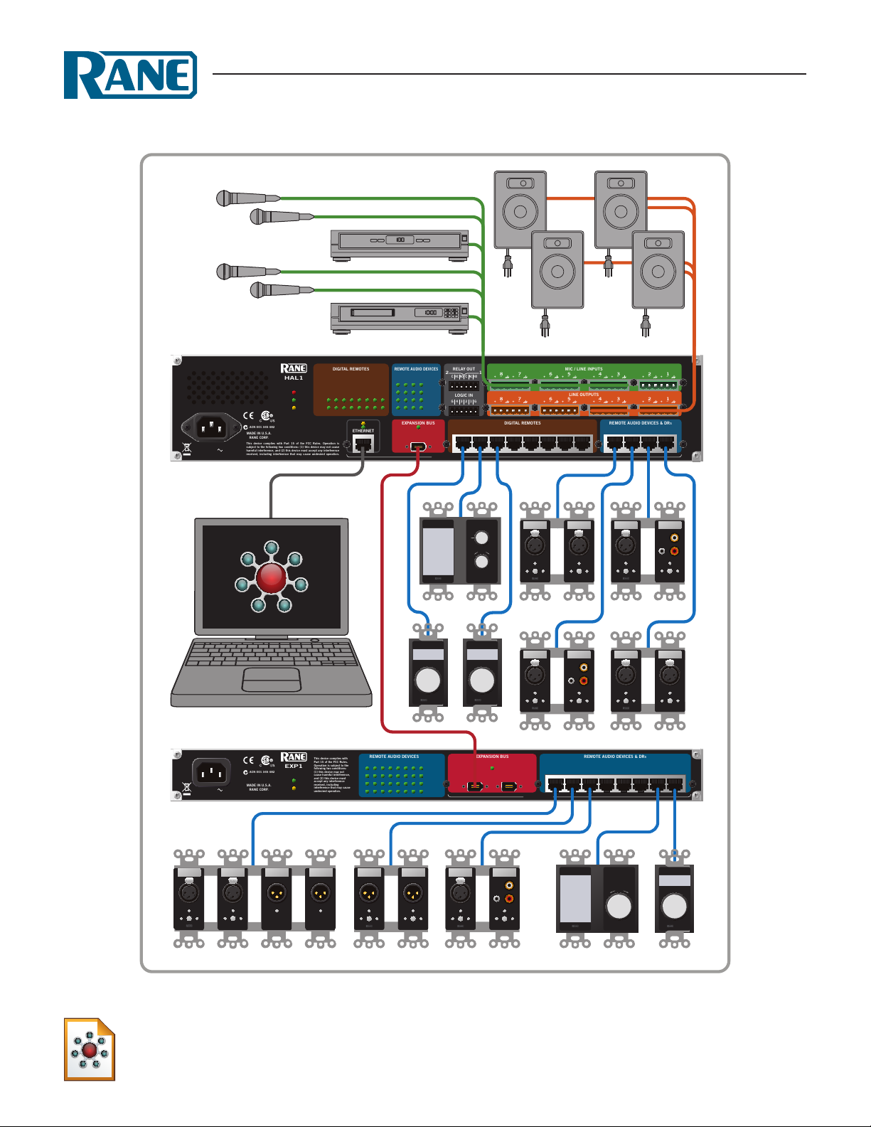
The primary hardware component in a HAL System is the HAL host device. There is only one HAL
device per system. HAL serves as the system's brain to which you connect other slave devices such as
analog audio equipment, Remote Audio Devices (RADs), Digital Remotes (DRs), Expansion Units
(EXPs), and more. Inside HAL is a DSP processor that manages the audio as well as a host processor
that manages other aspects of the system.
The following graphic provides a visual of an entire HAL System :
4
Page 9
CHAPTER 1: Getting Started
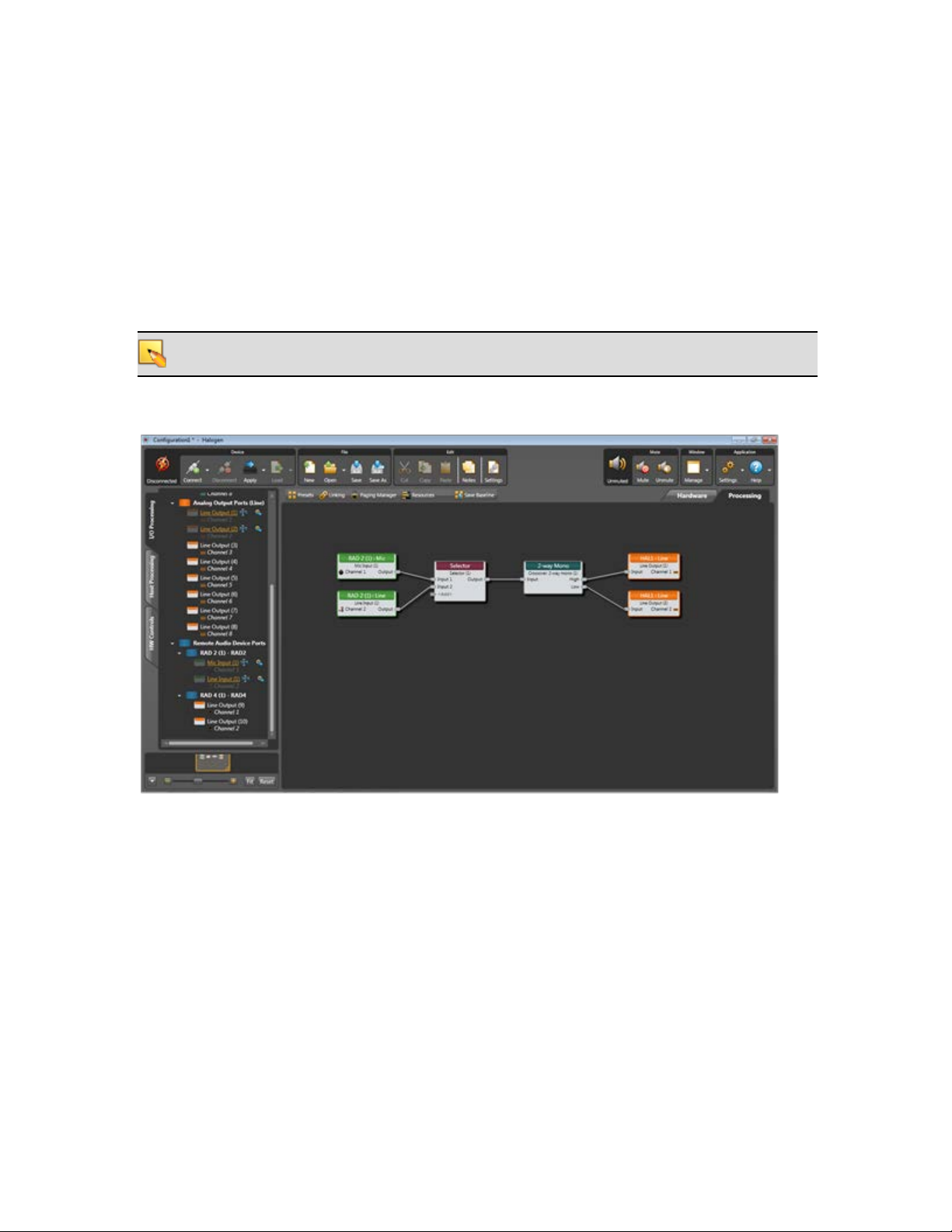
Software Component
Included in the HAL System is a software application, called Halogen, that you use to configure and
manage the entire system. Halogen contains two primary graphical workspaces, the Hardware Workspace
and the Processing Workspace, in which you simply drag and drop hardware components and processing
blocks to set up the audio system you want. You can work in online mode (connected to HAL) or offline mode (not connected to HAL or any other hardware). The ability to work in offline mode makes Halogen a powerful design tool available for use whether or not you have the hardware in hand. And not
only can you design your system without having hardware in place, you can also test your system before
you install the hardware! Now that's powerful!
NOTE: When working in online mode, changes made in the software are immediately implemented
and saved to HAL (with the exception of DSP changes that require a system recompile).
Below is a sample image of the Halogen Processing Workspace:
For more details on the Halogen software application, see "Introduction to the Halogen Software" on
page 40.
5
Page 10

HAL SYSTEM INSTALLATION GUIDE
System Requirements
To use a HAL System, the following items are required:
l
You must have access to a computer running Microsoft Windows XP (Service Pack 3 or higher),
Vista (Service Pack 1 or higher), or Windows 7. The computer must also have an Ethernet port,
which you use to connect the computer to the HAL device (either directly or via an Ethernet network). This connection is necessary for using the Halogen software to load configuration information into the device and also for monitoring detailed status information. Note that some status
information is visible on the hardware itself.
l
You must have administrative rights to install the Halogen software, but you do not need administrative rights to run the software.
l
Most RADs require two, three, or four-gang standard switchboxes (for installation into a wall). A
DR1 requires a one-gang switchbox, while a DR2 and DR3 require two-gang switchboxes.
Switchboxes used for both RADs and DRs must have a minimum depth of 2 1/4" (57 mm).
Minimum Requirements for Running Halogen
l
Windows XP SP3 (32-bit) or Vista SP1 (32 or 64-bit), or 7 (32 or 64-bit)
l
PC with 1.6 GHz Dual Core Processor (for example, Intel Core Duo, AMD Athlon X2)
l
1 GB RAM
l
2 GB available hard disk space
l
Display Resolution: 1024x768, 24 bit color
l
Ethernet adapter: 100baseT
l
DVD Drive for installation from DVD (or can install from Rane website)
Recommendations for Best Performance
l
Windows 7 (32 or 64-bit)
l
PC with mid-level processor @ 2GHz multi-core or better (for example, Intel i3, AMD Athlon II)
l
2 GB RAM
l
2 GB available hard disk space
l
Display Resolution: 1280 x 1024, 24-bit color
l
Display Adaptor: supports rendering tier 1 or 2 (see http://msdn.microsoft.com/en-us/library/ms742196.aspx) (i.e. directX 9.0 or greater)
l
Ethernet adapter: Gigabit
6
Page 11
CHAPTER 1: Getting Started
Administrative Rights Requirements
The following table outlines which Halogen tasks require administrative rights and which do not:
Requires administrative rights
l
Installing Halogen
l
Installing software updates to Halogen
l
Manually starting or stopping the Ranelink
Does not require administrative
rights
l
Running and using Halogen
l
Updating the HAL firmware
II service
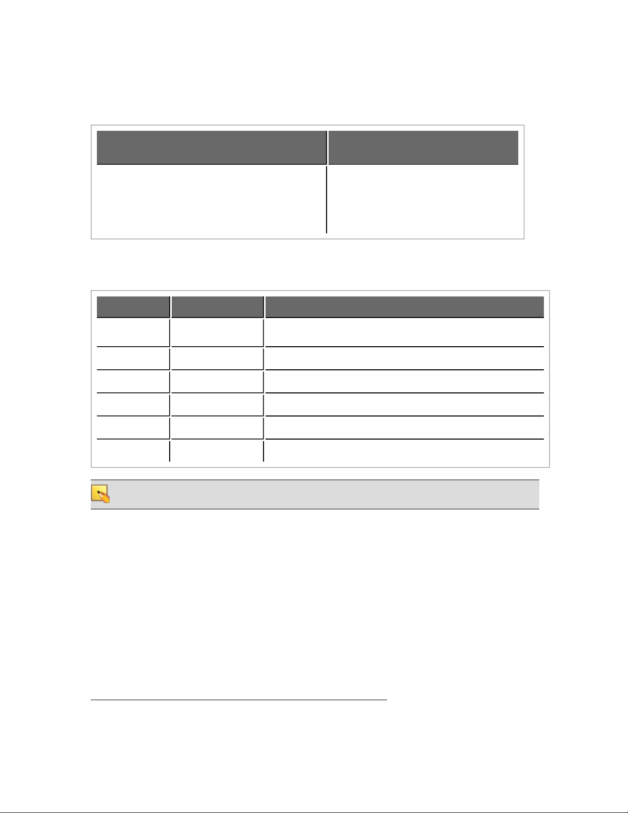
Required Ports
Halogen and HAL exchange information using the following ports and protocols:
Port Protocol Purpose
68 UDP DHCP Client (see note below)
4992 TCP Meter control messages
4993 TCP Configuration messages
4994 UDP Discovery broadcast messages
4994 TCP RaneLink II1communication messages
4995 TCP Meter data
NOTE: Halogen and HAL might both use port 68 to communicate with a DHCP server. This port is
not actually used for communication between Halogen and HAL.
HAL devices send occasional UDP broadcast messages. RaneLink II listens constantly for these messages
and, when it receives one, it does three things, if necessary:
l
Sets up a temporary link-local IP address (in other words, the address is cleared when the computer reboots) on the appropriate network interface card (NIC).
l
Adds an entry to the computer's network route table. RaneLink II maintains the list of HAL
devices and it must be running for Halogen to communicate with a HAL, even if the HAL has
been located by a manual search.
l
Opens and maintains a TCP connection with HAL so that it can receive status updates.
1
A service needed by Halogen to establish a connection with HAL.
7
Page 12
HAL SYSTEM INSTALLATION GUIDE
Required Processes
The following processes are required for working with the HALSystem and for establishing a connection between Halogen and HAL.
Process Purpose Location
Halogen.exe‡
Use to design your entire audio
system and connect to your HAL
device.
C:\Program Files\Rane Corporation\Halogen\Halogen.exe
Simulates the behavior of a HAL
when Halogen is not connected
hal1.pcops.exe‡
to a HAL. Allows for testing of
such things as control links and
C:\Program Files\Rane Cor-
poration\Halogen\hal1.pcops.exe
presets, even when not connected
to a HAL.
RaneLink.exe
A service needed by Halogen to
establish a connection with HAL.
C:\Program Files\Rane Cor-
poration\RaneLink\RaneLink.exe
‡If running 64-bit Vista or Windows 7, you can find Halogen.exe and hal1.pcops.exe in the Program
Files (x86) directory.
Using the HAL System Documentation
A variety of documentation is available to help you get started with and use your HALSystem:
Halogen Help System
A comprehensive help system is installed with the Halogen software. It contains all the information you need to work with the system. There are several ways to access the Help System:
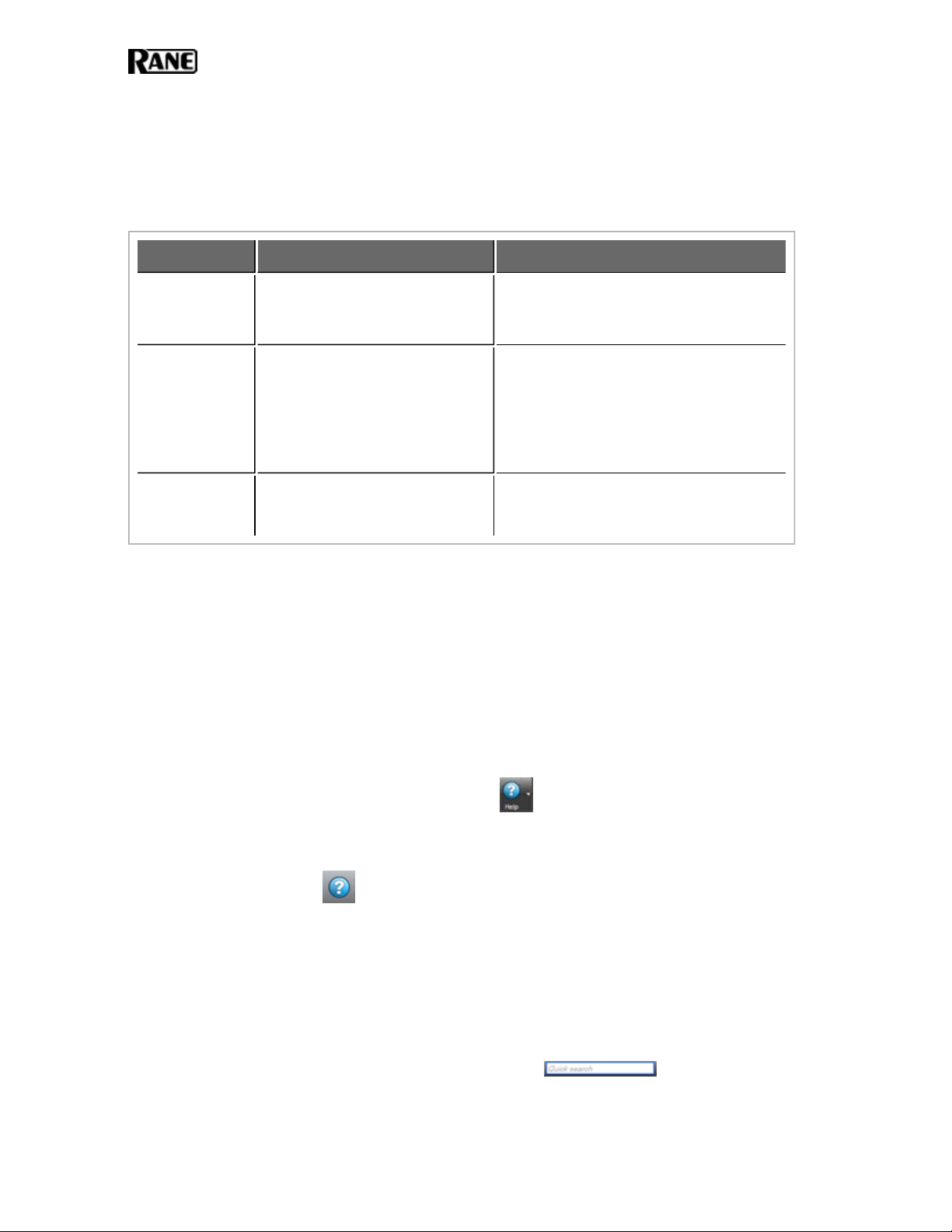
l
Click the Help icon on the application toolbar: Clicking the icon itself opens the
Help System. Clicking the down arrow displays a list of options including such things as
access to the Rane website, checking for updates to the Halogen software, and sending an
email to Rane.
l
Click the Help icon that appears in the upper right corner of Halogen dialog boxes.
Clicking this icon opens the Help topic related to the specific dialog box. From there you
can access the entire Help System, if needed.
l
Right-click on different elements in the user interface. A Help option appears in the context
menu. Click this option to open the relevant Help topic. Pressing F1 when an area of the
user interface has focus also displays its relevant Help topic.
l
To search for information within the Help System, you can use the tabs on the Help
Viewer's left pane to search the index (click the Index tab) or perform a full-text search
(click the Search tab). You can also use the Quick search box in the Help System toolbar
to search for text within the currently displayed topic:
8
Page 13

CHAPTER 1: Getting Started
HAL System Design Guide
This guide is offered as a PDF file and contains a product overview, details about the HAL System's key features, and best practices for designing a HAL audio system. Note that the information
in this guide is also available in the Halogen Help System. You can find this guide on the Rane
website as well as on the product DVD.
HAL System Installation Guide
This guide, the one you are reading, is offered in both a PDF and hardcopy format, and includes
step-by-step instructions on installing the HALhardware, loading a configuration, and testing the
system. This information is also included in the Halogen Help System. You can find this guide on
the Rane website and product DVD, and as a printed guide in the product package.
9
Page 14

CHAPTER 2: Hardware Component Details
This chapter provides details about the HALSystem hardware devices that you'll be installing.
HAL1 Device
The HAL1 host device (which is referred to as HAL throughout this guide) is the brain that controls the entire HALSystem. It can connect to a variety of other hardware (or slave devices) such
as analog equipment, RADs, DRs, and EXPs. Inside the HAL hardware is a host controller that
controls DSP operations and manages control links, presets, and more. There is only one HAL
device per system. You cannot connect one HAL to another.
NOTE FOR DRAG NET USERS: The DSP processing engine in the HAL1 device is four times
more powerful than the RPM88.
Maximum Device Connections
The device connections that are possible on a HAL1 are as follows:
l
4 Remote Audio Devices (RADs)
l
8 Digital Remotes (DRs)—Can add up to 4 more by plugging them into the RAD ports
l
1–4 Expansion Unit Devices (EXPs)
l
8 Mic/Line Inputs
l
8 Line Outputs
l
4 Logic Inputs
l
2 Relay Outputs
Other Functionality
In addition to hosting other hardware devices and managing system operations, HAL also does
the following:
l
Provides power to connected RADs, DRs, and EXPs
l
Stores configuration settings and compatible firmware for itself and for each connected
RAD, DR, and EXP
l
Provides a connection to an Ethernet network (for control of HAL and the connected
devices)
l
Displays various status indicators (LEDs) providing information about the health of the system
10
Page 15
CHAPTER 2: Hardware Component Details
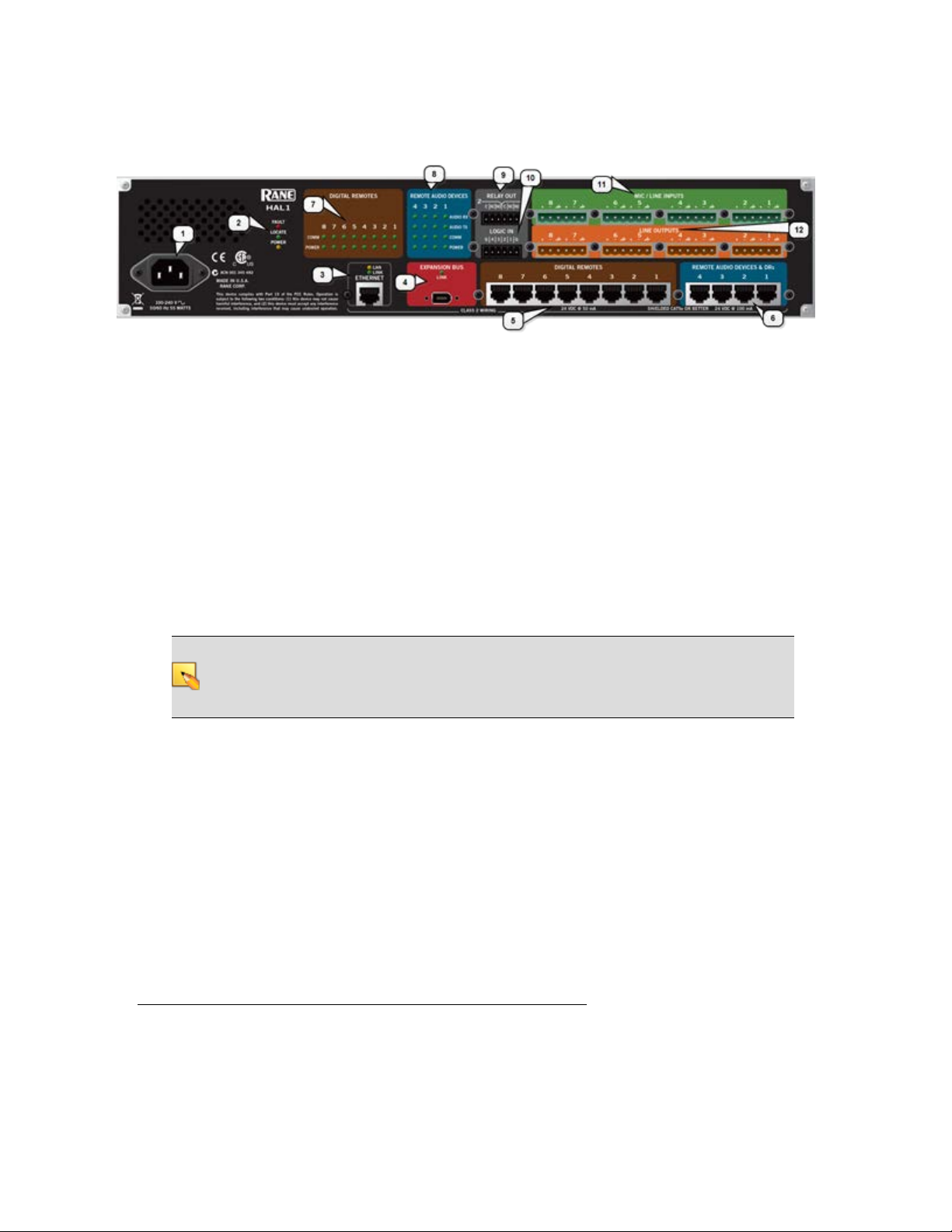
Rear Panel Description
1. The Power IEC jack connects to AC line voltage, 100-240 V, 50-60 Hz.
2. Fault, Locate, and Power LEDs
The Fault LED flashes red when something in the hardware goes awry. The first step in troubleshooting the problem is to open the Halogen software and check the status of this HAL
device.
The Locate LED flashes green when you place this HAL device in Locate Mode (via the Halogen software). The purpose of this Locate functionality is for verification, when working in the
software, of the physical device you are configuring or viewing.
The Power LED lights when the HAL hardware is powered on.
3. Ethernet port and LAN and Link LEDs
Use this port to connect HAL to an Ethernet switch or directly to a computer.
NOTE: This Ethernet port contains auto-MDIX functionality, which means that you can
use either a standard Ethernet patch cable or a crossover cable to connect to a computer or
Ethernet switch. The auto-MDIX functionality takes care of coordinating the proper connection between the devices.
The Ethernet LAN LED flashes when HAL detects any Ethernet packets on the network. The
Link LED indicates if the Ethernet network is connected. If HAL is connected to an Ethernet
network but the Link LED is off, there is likely a problem with the connection.
4. Expansion Bus LED and port
Use the Expansion Network port to connect an Expansion Network device (such as an EXP1)
to the HAL via Firewire1. To attach additional Expansion Network devices to your HAL System, use a Firewire cable to connect each new device to the previous device—in a daisy chain
style.
1
A form of connectivity similar to USB, meant to connect peripherals such as MP3 Players and digital
cameras to the computer. The HAL System uses FireWire to connect Expansion Units to the HAL
device. FireWire operates around 30 times faster than a USB 1.1 connection. FireWire is technically
known as IEEE-1394.
11
Page 16

HAL SYSTEM INSTALLATION GUIDE
If lit, the Expansion Network Link LED indicates that the Expansion Network device is communicating properly with HAL. If an Expansion Network device is properly connected to the
port yet the status LED remains dark, there is likely a problem with the connection.
5. Digital Remote Device ports
Use these ports to connect each DR to the HAL via a standard CAT 5 cable. You must use a
standard Ethernet patch cable for this connection. There are 8 DR ports on a HAL1 device. If
you need more than 8 DR connections, you can use a RAD port to connect a DR.
6. Remote Audio Device ports
Use these ports to connect each RAD to the HAL via a standard CAT 5 cable. You must use a
standard Ethernet patch cable for this connection. There are 4 RAD ports on a HAL1 device. If
you need more RAD connections, you will need to connect an Expansion Unit with RAD
ports (such as an EXP1) to your HAL device. You cannot connect a RAD to a DR port.
7. Digital Remote Device LEDs
Provides information about the health of the CAT 5 connection between each DR and HAL.
The numbers 1 through 8 correspond to the DR ports 1 through 8 in the lower area of the rear
panel. The Comm LED (on the top row) lights solidly if the DR's data communications pair is
working properly. The Power LED (on the bottom row) lights solidly if HAL is supplying
adequate power to the DR port.
8. Remote Audio Device LEDs
Provides status information about the health of the CAT 5 connection between each RAD and
HAL. The numbers 1 through 4 correspond to the RAD ports 1 through 4 in the lower right
corner of the rear panel. For example, the LEDs for number 1 provide information about the
RAD connected on port 1. Each LED corresponds with one twisted pair within the CAT 5
cable. If the twisted pair is functioning properly, the LED displays a solid green light.
l
Audio Rx LED—lights solidly if the HAL receive pair is working properly.
l
Audio Tx LED—lights solidly if the HAL transmit pair is working properly.
l
Comm LED—lights solidly if the RAD's data communications pair is working properly.
l
Power LED—lights solidly if HAL is supplying adequate power to the RAD port.
NOTE: The Remote Audio Device LEDs on the front panel differ from those on the rear
panel. The front panel LEDs provide information about signal activity on each audio
channel. See the "Front Panel Description" on next page for more details.
9. Relay Out ports
Reed relay ports used to signal another device. A common implementation is to link a relay
port to a Toggle control so that an end user can change its value. Also, the Halogen software
contains a checkbox for each relay port, the value of which you can include in a preset or link
to another control, making it possible to use a preset or control to turn the relay port on or off.
HAL1 contains two Relay Out ports.
12
Page 17
10. Logic In ports
Use these TTL 5-volt digital logic input ports to communicate to the HAL System via an external control device. You can configure each Logic In port to control a selector, toggle, or command within the HAL System. For example, you might use a Logic In port to select between
two audio channels, or to mute the whole system.
11. Mic/Line Input ports
Use these ports to connect up to 8 analog microphones or line input devices. Note that the Mic
In ports support phantom power.
12. Line Output ports
Use these ports to connect up to 8 analog line output devices, such as amplifiers.
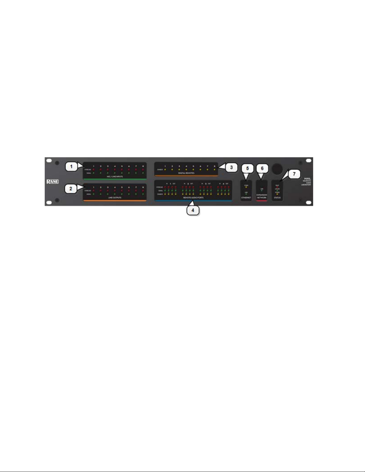
Front Panel Description
CHAPTER 2: Hardware Component Details
1. Mic/Line Inputs LEDs
Provides status information about the mic/line analog inputs connected to the HAL. The
numbers 1 through 8 correspond to the mic/line input ports 1 through 8 on the rear panel.
These LEDs provide information on the following:
l
Overload LED (red) – indicates that the mic/line input is experiencing a signal overload
l
Signal LED (green) – indicates the presence of an audio signal on the mic/line input
2. Line Outputs LEDs
Provides information about the HAL analog outputs. The numbers 1 through 8 correspond to
the line output ports 1 through 8 on the rear panel.
These LEDs provide information on the following:
l
Overload LED (red) – indicates that the line output is experiencing a signal overload
l
Signal LED (green) – indicates the presence of an audio signal on the line output
3. Digital Remotes LEDs
Indicates which Digital Remotes are enabled. Each numbered LED corresponds to the Digital
Remote port with the same number. If a Digital Remote is connected on a port but its Enabled
LED is off, there is likely a problem with the CAT 5 connection or with the Digital Remote
itself. If an Enabled LED is flashing, it indicates that the physical Digital Remote model does
not match the Digital Remote model specified for this port in the HAL configuration.
13
Page 18

HAL SYSTEM INSTALLATION GUIDE
4. Remote Audio Ports status indicators
Provides information about the RAD audio channels. The numbers 1 through 4 at the top of
the front panel correspond to the RAD ports 1 through 4 on the back of the HAL. For example, the LEDs for number 1 provide information about the RAD connected on port 1.
Under each RAD number are LEDs for four audio channels, two input and two output. These
four LEDs represent the maximum number of channels a RAD is capable of transporting. However, not all RAD models use all four channels. For example, the RAD1 model provides two
microphone inputs, so for that model, only the two columns of indicators labeled IN would be
active.
These LEDs provide information on the following:
l
Overload LED (red)–indicates that the channel is experiencing a signal overload
l
Signal LED (green)–indicates the presence of an audio signal on this channel
l
Enabled LED (yellow)–indicates the availability of the associated audio channel. If a
RAD is connected on this port and all Enabled lights are off, this indicates a problem
with the CAT 5 connection or with the RAD. If the Enabled LEDs are flashing, this
indicates that the physical RAD model does not match the RAD model specified for
this port in the HAL configuration.
5. The Ethernet Comm and Link LEDs
Provides status information about the HAL Ethernet connection.
l
Comm LED (yellow) – flashes when HAL has been discovered by at least one PC running RaneLink II1, is solid when Halogen is exclusively connected to HAL, is off
when HALhas yet to be discovered.
l
Link LED (green) – indicates if the Ethernet network is connected. If the HAL is connected to an Ethernet network but the Link LED is off, this indicates a problem with the
connection.
6. The Expansion Network LED
If lit, indicates that an Expansion Network device is properly connected to the HAL. If an
Expansion Network device is properly connected to the port and powered on yet the status
LED remains dark, there is likely a problem with the connection.
7. Fault, Locate, and Power LEDs
The Fault LED flashes red when something in the hardware goes awry. The first step in troubleshooting the problem is to open the Halogen software and check the status of this HAL
device.
The Locate LED flashes green when you place this HAL device in Locate Mode (via the Halogen software). The purpose of this Locate functionality is for verification, when working in
the software, of the physical device you are configuring or viewing.
The Power LED lights when the HAL hardware is powered on.
1
A service needed by Halogen to establish a connection with HAL.
14
Page 19
CHAPTER 2: Hardware Component Details
Remote Audio Devices
The primary purpose of a Remote Audio Device (RAD) is to amplify, digitize, and transmit a digital
audio signal via CAT 5 cable to a HAL host device. RADs can also receive a digital signal from the
HAL and then convert it to analog before sending it to its attached audio equipment. RADs are capable
of transmitting and receiving up to four channels of digital audio (two in each direction). To better fit
your needs, however, Rane offers various RAD models. Most RAD models are designed to fit in a standard U.S. two, three, or four gang switchbox.
The HAL System offers a variety of RAD models, each of which serves a unique purpose. For example, a
RAD1 contains two microphone input channels. When you design an audio system, you choose the
RAD models that are appropriate for your application. You must then provide configuration information
to HAL so that it knows which RAD models to expect on each port and what information to send to
each RAD. For more information, see "Available RAD Models" in the Halogen Help System. You can
also read about the available RAD models on the Rane website.
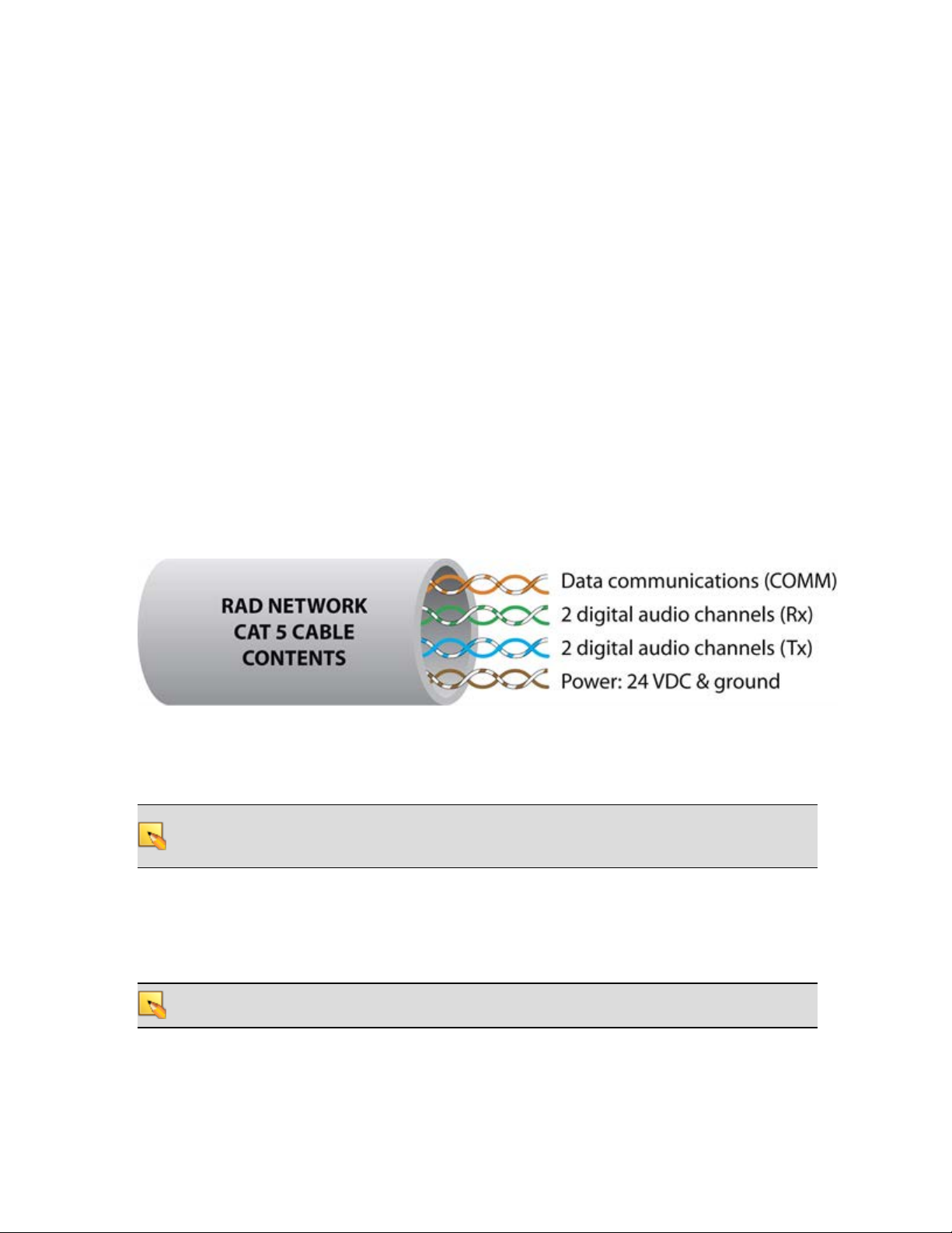
How the CAT 5 Cabling is Utilized
The CAT 5 cable that connects the RAD to HAL also provides power to the RAD as well as a path for
data communications. Data communications makes it possible to control the RAD’s configuration settings, view status information, and update a RAD’s firmware – all from the host HAL device. The following picture illustrates how the four twisted pairs within the CAT 5 cable are utilized.
l
The orange pair is reserved for data communications between the RAD and HAL. Data communications is needed for such things as sending configuration information from HAL to the
RAD, sending firmware updates from HAL to the RAD, and sending status information from the
RAD to HAL.
NOTE: Configuration information for a specific RAD (for example, LED intensity, microphone sen-
sitivity, and RAD and channel names) is stored in the HAL device, not in the RAD. This makes it
easy to swap in a new RAD, if necessary, without losing configuration data.
l
The green and blue pairs carry two channels each of balanced, differential, digital audio. Tx refers
to audio that the RAD sends to the HAL. Rx refers to audio that the RAD receives from HAL.
l
The brown pair provides 24 VDC power and ground for the RAD. This is (obviously) the wire
you should check if it appears a RAD is not receiving power.
NOTE: Digital Remotes (discussed on page 20) use only the orange pair (for data communications)
and the brown pair (for power).
15
Page 20
HAL SYSTEM INSTALLATION GUIDE
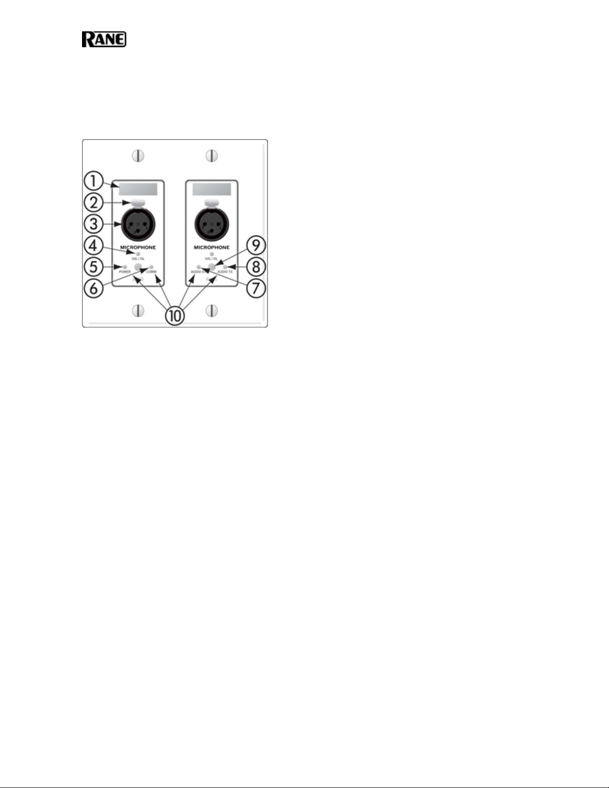
The Parts of a RAD
Following is an illustration of the front of a typical RAD, accompanied by descriptions of the RAD’s
various hardware features:
1. Label: a location on the RAD for inserting a custom label. One possible use of this label is to
identify the channel number associated with the corresponding jack.
2. XLR Tab: push tab for releasing a microphone cable. If you do not need this tab, you should
remove it before installing the RAD. For more information, see the RAD installation instructions beginning on page 31.
3. Input/Output jacks: the actual jacks to which you connect the appropriate audio device(s). The
jacks differ based on the RAD model.
4. Sig/OL LED: displays a green light when an audio signal is detected, displays a red light
when the channel is experiencing a signal overload.
5. Power LED: displays a solid green when the RAD is receiving power, displays solid red if the
voltage received is lower than expected.
6. Comm LED: displays a solid green when the RAD detects two things—the communication
pair of wires and that communication is established between the HAL and RAD. The light displays solid red if the RAD cannot communicate with the HAL. This is likely due to a problem
with the communications pair of wires.
7. Audio Rx LED: displays solid green when the RAD detects that the pair of wires for receiving audio is functioning properly, regardless of the RAD model. Displays red if there is a problem.
8. Audio Tx LED: displays solid green if communication with the HAL has been established
and the HAL informs the RAD of the Tx Audio lock. Displays solid red if there is a problem
communicating with the RAD or if there is a problem with the Audio Tx pair of wires.
9. Light sensor: detects the amount of light in the room and dims or brightens all LEDs appropriately—primarily to prevent the LEDs from glowing in a darkened room like cat eyes on Halloween. Note that you cannot turn these LEDs off manually. This is by design. We wanted to
avoid the possibility of someone erroneously thinking the RAD is defective (because the
power light is off) and attempting to replace it unnecessarily.
16
Page 21
CHAPTER 2: Hardware Component Details
10. Locate mode: The Halogen software application contains a feature allowing you to verify the
physical location of a specific RAD or HAL device. When you place a RAD in Locate mode,
the Power, Comm, Audio Tx, and Audio Rx LEDs on the front of the corresponding RAD flash
green. The flashing continues until you cancel the request in the software, place another RAD
in Locate mode, interrupt the connection between the computer and the HAL, disconnect the
RAD, or power cycle the HAL. Mismatch mode: When a RAD is connected to a RAD port on
the back of a HAL, a comparison is made between the physical RAD model and the RAD
model specified for this port in the HAL configuration. If there is a mismatch the Power, Comm,
Audio Tx, and Audio Rx LEDs on the front of the corresponding RAD flash red.
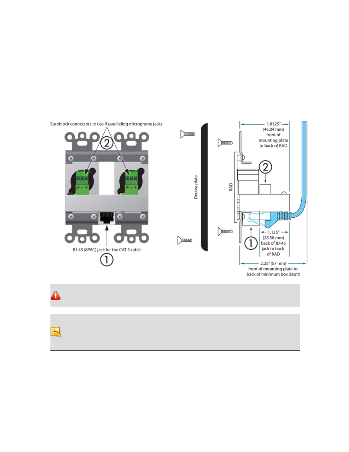
Following is an illustration of the back and side of a typical RAD:
WARNING! As it is poor design to plug two microphones into a single microphone input, we do
not recommend this practice. If, however, you have a situation that warrants it, proceed with caution. We recognize that paralleling microphone jacks can lower the cost of your audio system.
NOTE: RADs are hot-swappable. In other words, you can replace a RAD without having to power
down the system. The HAL automatically detects the new RAD and configures it using the configuration data stored in the HAL. If the configured RAD and the physical RAD do not match, the
HALfront panel Enabled LEDs for this RAD flash yellow. At the same time, the RAD's Power,
Comm, Audio Rx, and Audio Tx LEDs flash red.
17
Page 22

HAL SYSTEM INSTALLATION GUIDE
Pager1 RAD
Setting up paging in the HALSystem is as easy as adding zones to groups (called Scenarios), and then
specifying the Scenarios into which each paging station can page into. The paging hardware (the
Pager1 RAD) then displays the Scenario options available at that station. The user selects the desired
Scenario, waits for the Ready green light indicating that all zones in that Scenario are ready to hear a
message, presses the talk button, and speaks into the microphone.
The Pager1 hardware, which is automatically discovered by the system when connected to a HAL, is a
table-top RAD that accepts a gooseneck via a locking 3-pin XLR connector for increased security.
The Pager1 also includes the following set of paging controls:
l
A selectable list of available Paging Scenarios
l
Indicators for Busy, Caution, and Ready (referring to the selected Scenario).
l
The Busy indicator lights when zones in the selected scenario are in use by a higher or
same priority page.
l
The Caution indicator lights when zones in the selected scenario are in use by a lower
priority page.
l
The Ready indicator lights when all zones in the scenario are free to page into.
l
A talk button
l
Signal and Overload LEDs
1
On the following page is an annotated image of a Pager1 device.
1
One or more paging zones treated as a group for paging purposes. Paging Scenarios are defined and
named by the designer, who then also assigns specific Scenarios to specific Paging Stations. End users
always page into Scenarios.
18
Page 23

CHAPTER 2: Hardware Component Details
AM1 and AM2 RADs
The Automixer 1 (AM1) is a mixer that expands the available microphone channels as well as line
inputs, making it easy for an inexperienced operator to quickly set up and manage the audio for a small
multimedia presentation involving up to four participants using wired or wireless microphones as well as
several additional program sources (such as a laptop computer or a DVD player).
The Automixer 2 (AM2) is a cascadable mixer that expands into the AM1 or other AM2s and increases
the number of microphones by eight or more, but does not expand line inputs. Both products provide
superior audio processing with a simple user interface.
For more details, see the manuals that accompany the AM1 and AM2. More information on these RADs
is also available in the Halogen Help System.
19
Page 24

HAL SYSTEM INSTALLATION GUIDE
Digital Remote Devices
The Halogen software gives you microscopic control over almost every aspect of your audio system.
This detailed control is great for the system designer, but not so great for end users who simply want to
turn up the volume. The last thing they want to do is open a software program! Digital Remote (DR)
hardware devices, a variety of which are available for your HALSystem, provide system users with
easy control of volume, audio selection, preset activation, and more—out in the locations where the control is needed.
A huge advantage of these DR devices is their plug-and-play nature. When you connect a DR to the
system, HAL automatically discovers and addresses it. In addition, just as with RADs, DRs use pointto-point wiring which eliminates problems of cable length, termination, and addressing. Troubleshooting time is also reduced because of DR status indicators on the HAL that immediately report
the DR wiring status. And, finally, designers can test remote operation with or without the actual hardware. This offline testing is possible because of the Halogen software representation of each remote in
the system.
DRs connect to the HAL via DR ports, which are basically the same as RAD ports but with no audio.
In other words, the DR ports provide a communications link and power, but no AES31digital audio.
Because RAD ports contain all the functionality needed by a DR, you can also connect DRs to RAD
ports (if, for example, all your DR ports are full and you have a RAD port available). The opposite is
not true, however. You cannot connect a RAD to a DR port.
Some DR models (DR2 and DR3) can behave in a variety of ways. You use the Halogen software to
configure their behavior. You can also enable and disable the individual controls on a DR (both manually, via control links to other remotes, and through the use of presets). For details, see the Halogen
Help System.
NOTE FOR DRAG NET USERS: Digital Remotes serve a similar function as the Smart Remotes
used with Dragnet products. There is a key difference, however. Smart Remotes are multi-drop
devices that must be daisy-chained together. Because they share bandwidth and power, the more
Smart Remotes you connect, the slower the communications and the more sag in power delivery.
DRs, on the other hand, are each connected directly to the HAL System and are, therefore, able
to provide consistent, high performance. In addition, unlike Smart Remotes, you no longer have
to worry about device addresses, cable length, cable termination, troubleshooting of the wiring,
or complex processes for linking controls to audio processing.
1
A standard from the Audio Engineering Society used for the transport of digital audio signals between
professional audio devices.
20
Page 25

CHAPTER 2: Hardware Component Details
Available Digital Remote Models
Following are the types of DRs currently available for your HAL System. The DR models available will
vary over time as Rane's engineers ponder and design new and better ways to remotely control an audio
system. For the most current list of DRs, see the Rane website.
NOTE: Each of these DRs mounts inside a US one-gang or two-gang switchbox. See the Rane web-
site for a detailed listing of acceptable models of switchboxes. Note that the Decora plates for the
DRs are included.
NOTE FOR DRAG NET USERS: Remember the SR3 remote for Drag Net systems and how it was too
wide to allow the mounting of two or more of them beside each other in a standard switch box?
You will be happy to know that the HAL System DRs can be mounted directly beside each other
in any combination, allowing you to use several DRs in the same two, three, or four-gang switchbox.
NOTE: DR display screens are dynamic, automatically updating when the available options change
through preset activation, room combining, and so on. Therefore, the user always sees the options
that are currently available.
DR1
A DR1 provides a single level control. A DR1 is used most commonly to control volume.
NOTE: A DR1 requires a one-gang standard switchbox for installation into a wall.
21
Page 26

HAL SYSTEM INSTALLATION GUIDE
DR2
A DR2 works well for selecting sources, presets, and room configurations. You can configure a DR2 to
behave in one of two ways:
l
Single Selector: The control acts as a selector switch that can select only one item on the display
screen. For example, the display screen might show a list of background music channels. The
user uses the push control to select which channel to activate. This behavior is similar to a radio
button in a software application (as displayed in the image below).
l
List of Toggles/Commands: The control acts as a switch for enabling or disabling each item on
the display screen. For example, the display screen might list presets and the user uses the push
control to enable or disable each preset in the list. This behavior is similar to a series of checkbox items in a software application.
NOTE: A DR2 requires a two-gang standard switchbox for installation into a wall.
22
Page 27

CHAPTER 2: Hardware Component Details
DR3
The DR3 is extremely flexible, as it can control both selection and volume. You can think of the DR3 as
two different remotes—a selector and a level. One knob makes a selection, the other knob changes the
volume.
You can configure a DR3 in one of three ways:
l
Single Level & Selector: Control a level and selection from the same remote. For example, you
could use a DR3 to select the background music source and control the volume in a room.
l
Single Level & List of Toggles/Commands: This option allows you to control a single level and
multiple other items. For example, you could use a DR3 to control the volume in a room as well
as activate/deactivate one or more listed presets that change the audio and control parameters for
the room.
l
List of Levels: Choose from multiple levels. For example, you could use a DR3 to control the volume in multiple rooms or zones from a single DR located at a hostess station or in a manager's
office.
NOTE: A DR3 requires a two-gang standard switchbox for installation into a wall.
23
Page 28

HAL SYSTEM INSTALLATION GUIDE
Expansion Units
A single HALdevice contains a fixed number of inputs, outputs, RAD ports, and so on. So what do
you do if your audio system requires more connections than are available on the HAL you purchased?
Rane's crackerjack engineers anticipated and resolved this capacity issue by designing HAL to be
expandable, allowing you to pick and choose between various Expansion Units to create a HAL System that fits your needs. For example, if you purchased a HAL1 but you need more than four RAD
ports, you can attach the Expansion Unit known as the EXP1 to your HAL and suddenly have eight
more RAD ports in your system. Remember that you can also connect DRs to RAD ports, so you could
use the EXP1 to expand your DR connections as well.
Expansion Units connect to HAL via a FireWire1expansion network, which is similar to a USB cable
and does not require IP addresses. The only limitation when using FireWire is its maximum cable
length of 15 feet. Given that the purpose of Expansion Units is to expand the HAL host device capabilities within a single rack room, this FireWire distance limit should not pose a problem.
In addition to connecting the physical Expansion Unit hardware to your HAL device, you must also
add the Expansion Unit to your HAL configuration.
NOTE: You can connect a maximum of four input Expansion Units to a HAL1 device.
1
A form of connectivity similar to USB, meant to connect peripherals such as MP3 Players and digital
cameras to the computer. The HAL System uses FireWire to connect Expansion Units to the HAL
device. FireWire operates around 30 times faster than a USB 1.1 connection. FireWire is technically
known as IEEE-1394.
24
Page 29

CHAPTER 3: Installing Your HAL System
This chapter includes all the details for the seven steps required for installing your HALSystem.
Task 1: Install and Connect HAL
You can work on-site or off-site to install the HAL into the audio rack. Following are a few
things to consider for each approach;
l
If installing on-site, we recommend that you install, connect, power on, and configure the
HAL (and EXP devices, if needed) and install and terminate the CAT 5 cable prior to
installing the RADs and DRs. Done in this order, you can verify that the RADs and DRs
are working properly as soon as you connect them.
l
If installing off-site, you will obviously not be installing the RADs and DRs into walls.
We do recommend, however, that you load the configuration file and connect the RADs
and DRs to the HAL during the off-site installation so that you can fully test the configuration.
TIP: Now is also a good time to label the RADs to ensure that you install and connect the
same RADs in the same HAL (or EXP) ports on which they were tested. See "Generating
Device Labels" on page 45 for details on generating and attaching labels. Because DRs
have LCD display screens, there is no need to generate physical labels for them.
TIP: If it's not possible to install CAT5 cabling in your installation but you want to use
RAD functionality and/or have more than 8 inputs and 8 outputs, a nice solution is to
install RADs in the rack using special expansion devices. We suggest you take a look at
the rack device products by Lowell (specifically the LD9-RMP) or by Radio Design Labs
(specifically the RM-D9 rack mount product).
Installing HAL in your Audio Rack
Following are the detailed steps for installing the HAL hardware into the audio rack and connecting it to your Ethernet network. You can rely on the LED indicators on the hardware for
basic device and connection status information. To see more details about the system status, however, you’ll need to install the Halogen software. But first, let’s start with the hardware. To
review the front and rear panel hardware details, see "HAL1 Device" on page 10.
To install and connect the HAL:
1. Attach the HAL (and all other audio equipment) to the audio rack.
2. If the system will be using an Ethernet network, connect the HAL to it. Plug one end of
a standard Ethernet patch cable (or an Ethernet crossover cable) into the Ethernet port on
the back of the HAL. Plug the other end into the Ethernet network switch. An Ethernet
crossover cable is provided with the product.
25
Page 30

HAL SYSTEM INSTALLATION GUIDE
NOTE: If there is no Ethernet network, you can skip this step for now. You will use this
port later to connect a computer directly to the HAL (for configuration and management
of the device).
WARNING! If your network requires that the HAL use one or more static IP addresses,
you should configure these addresses prior to connecting the HAL to your network. To
do so, install and start the Halogen software, connect your computer directly to the
device, and then open the device and configure its IP address(es). For details, see "Working with DHCP, Static IP Addresses, and Routers" below.
3. Using the IEC power cord provided with the product, connect the HAL to a power outlet or
power strip. The Power LED located on both the front and rear panels of the HAL lights up.
4. Verify that the Ethernet connection is working properly.
l
When plugged into any working Ethernet port, the Ethernet Link LED (located on both
the front and rear panels) lights up.
l
If there is activity on the network (in other words, network packets are being transmitted), the Ethernet LAN LED (on the rear panel) flashes.
l
The Ethernet Comm LED (on the front panel) flashes if the HAL hardware is communicating with at least one PC that is running RaneLink II. The LED is solid when
Halogen is connected to HAL.
5. If the CAT 5 cabling for the RADs and DRs has already been installed and terminated, connect the cables to the appropriate RAD and DR ports on the rear panel of the HAL (and EXP
devices, if applicable).
Working with DHCP, Static IP Addresses, and Routers
Does your installation require the use of DHCP or static IPaddresses? Never fear, it's as simple as can
be. But there are a few things you need to know as well as a few issues that could arise:
l
To configure a static IP or enable DHCP on a HAL, you should first connect to the HAL via its
link-local address. In other words, it is best to configure these addresses prior to connecting the
HAL to your network. To do so, install the Halogen software (see "Installing and Starting the
Halogen Software" on page 42), connect your computer directly to the HAL device (see "Task 3:
Configuring HAL" on page 28), start Halogen, connect to the HAL from within Halogen, and
then open the HAL properties (by clicking the HAL device properties icon in its title bar in the
Halogen Hardware Workspace—see the Halogen Help System for details), and then configure its
IP addresses (or enable DHCP). Once the system is installed at the site, you (and all subsequent
users) may need to type in a static IP address to connect to the HAL, so you should write this
IPaddress down somewhere!
NOTE: The subnet mask used for all HAL static IP addresses is CIDR 24 or 255.255.255.0.
l
On a local network, Halogen always uses the link-local IP to connect to HAL. Behind a router,
Halogen uses one of HAL’s static IPs or a DHCP-assigned IP—provided the user knows it and
types it into the Search field in the Connect to Device dialog box. Because link-local con-
nectivity is automatic, the user should never need to search for a HAL by its link-local IP
address.
26
Page 31

CHAPTER 3: Installing Your HAL System
NOTE: If your HAL is located behind a router and Halogen is unable to find the HAL,
check with your ITdepartment to find out if the router has NAT (Network Address Translation) enabled. If not, enable it and try again.
l
Although Halogen does not prevent you from adding a static IP that conflicts with a static IP on
another machine on the network, it will reject the addition of a static IP that conflicts with an IP
already configured on the HAL. If you attempt to add a conflicting IP address, Halogen displays a
failure message.
l
Similarly, enabling DHCP on a HAL that already has one or more static IPs configured can result
in a static IP being deleted if that static IP is on the same subnet as the dynamic IP acquired. HAL
deletes the conflicting static IP rather than reject the dynamic IP.
Task 2: Installing and Connecting HAL Expansion Units
Installing and connecting an EXP device is simple. Just as with the HAL device, you can rely on the
EXP's LED indicators to provide you with basic device and connection status information. The first EXP
that you install connects directly to the HAL. Subsequent EXP devices can be installed but are then
daisy-chained together. You will need FireWire cables to connect these devices.
NOTE: The HAL1supports a maximum of four input EXP devices.
To install a single EXP device:
1. Attach the EXP device to the audio rack.
2. Connect the EXP device to the HAL. You need a FireWire cable for this connection, with a
maximum cable length of 15 feet. To connect the EXP to the HAL, plug one end of the FireWire cable into the Expansion Bus on the HAL. Plug the other end of the cable into one of the
Expansion Bus slots on the EXP. You can use either one of the slots:
When HAL recognizes the EXP device, the Link light on the EXP turns green.
27
Page 32

HAL SYSTEM INSTALLATION GUIDE
To install more than one EXP device:
1. Install the first EXP as described on the previous page, connecting it directly to the HAL.
2. Attach the remaining EXP devices to the audio rack.
3. Daisy chain the EXP devices together. In other words, connect the second EXP device to the
EXP that is connected to the HAL. To do so, plug one end of the FireWire cable into the open
Expansion Bus slot on the first EXP. Plug the other end of the cable into one of the Expansion
Bus slots on the second EXP. Then, using another FireWire cable, repeat this process, connecting the third EXP to the second EXP, and so on:
Task 3: Configuring HAL
Although listed as the third task in the installation process, this task can occur later in the process if
necessary. To help with troubleshooting, however, we recommend loading the configuration file prior
to installing the RADs and DRs.
NOTE: If you do not have a configuration file, but you want to test that the equipment is working
properly, you can create a very simple configuration for verification purposes. It’s best to do this
after installing the RADs and DRs. See "Creating a Verification Configuration" on page 38.
To load a configuration file into a HAL:
1. Verify that the HAL is powered on and working properly.
2. If you haven’t done so already, download and install the Halogen software. See "Installing and
Starting the Halogen Software" on page 42.
28
Page 33

CHAPTER 3: Installing Your HAL System
3. Connect your computer to the HAL. You have two options: connect your computer directly to
the HAL or, if the HAL is connected to a network, connect your computer to that same network.
l
If making a direct connection, you’ll need to plug a standard Ethernet patch cable or a
crossover cable into the Ethernet port on the HAL and on your computer. A crossover
cable is included with the HAL equipment.
l
If connecting to the network, you can connect your computer to the same network switch
to which the HAL is connected or connect to the network in some other way. For example, if a wireless access point is available, you may want to use it so that you can roam
with a laptop and still communicate with the HAL. To connect to a switch, plug one end
of a standard Ethernet patch cable (or crossover cable) into the Ethernet port on the HAL
and the other end into a port on the network switch.
4. Connect to the HAL device:
1. From the Device menu in the Halogen application toolbar, click Connect.
2. In the Connect to Device dialog box that appears, find the HAL device you want.
3. Click the Connect button associated with that HAL device.
NOTE: The Connect to Device dialog box contains a Connection Status column that pro-
vides information on the status of each detected HAL. If the firmware version in the HAL
matches the expected firmware version of the Halogen software, the Connection Status is
Available. If the firmware version in the HALis older than the version expected by Halogen, the Connection Status is Device Firmware Older and the Operations column dis-
plays an Update Firmware button. For details, see "Upgrading Halogen Software and
HAL Firmware" on page 43.
5. Load the configuration file:
1. From the Device menu on the application toolbar, click Load.
2. From the Browse dialog box that opens, search for and select the configuration file you
want to load.
3. Click Open to load the file.
NOTE: The configuration settings are immediately applied and saved to the HAL.
If the HAL detects any mismatches between the configured peripheral devices
and the physical peripheral devices connected to the HAL, these mismatches are
reported in the Hardware Workspace. If you are loading the configuration prior
to installing any peripheral devices, each configured port will report an error
because it expects to find a specific device, but instead it finds nothing. When
the correct device models are installed, these errors disappear.
6. Check to see if the audio designer included any special notes with the configuration file. To do
so, click Notes in the Edit area of the Halogen application toolbar.
7. If you need to provide a custom name for the HALdevice, open its properties by double-clicking its title bar (in the Hardware Workspace) or by hovering and clicking the properties icon
29
Page 34

HAL SYSTEM INSTALLATION GUIDE
that appears in its title bar. Customize its name in the edit box located at the top of its properties dialog box:
NOTE: This device name is saved to the device, but it is not saved to the configuration
file. This is also true for any notes you may enter in this properties dialog box.
8. Make any other edits necessary to complete the configuration. Typically, none are needed.
Task 4: Pulling and Terminating CAT 5 Cabling
You can terminate and plug in the CAT 5 cable prior to or after installing the HAL into the audio rack.
We recommend that you install the cable and the HAL before installing the RADs and DRs. If you’re
curious how the twisted pairs within the CAT 5 cable are utilized for audio transmission, data communications, and power, see the illustration and explanation on page 15. Knowing how the wires are
used can be helpful when troubleshooting the system.
Following are a list of things to consider when installing the CAT 5 cable:
l
The maximum allowed distance of CAT 5 cable connecting a RAD or DR to a HAL is 150
meters (500 feet). The audio design dictating your installation most likely takes this limitation
into consideration. But it’s important to double-check that no CAT 5 cable you pull exceeds this
distance.
l
We recommend that you clearly label each end of each CAT 5 cable you install. This makes it
much easier to connect the proper CAT 5 cable to the proper port on the back of the HAL and to
the RADs and DRs. It also helps guarantee that you install the proper RAD and DR in each designated location.
l
Speaking of labels, you should generate and insert a label into each RAD prior to installing it.
It’s possible you did this during an off-site build of the audio rack. If the audio designer did not
provide you with labels, you can generate and print them yourself from within the Halogen software or you can use the default labels supplied with each RAD. See "Generating Device Labels"
on page 45 for details. If the RADs are not available yet, you can still generate the labels and
insert them later. DRs do not need labels, as they have LCD screens that display their configured
names.
l
Most RADs require two, three, or four-gang standard switchboxes (for installation into a wall). A
DR1 requires a one-gang switchbox, while a DR2 and DR3 require two-gang switchboxes.
Switchboxes used for both RADs and DRs must have a minimum depth of 2 1/4" (57 mm).
30
Page 35

CHAPTER 3: Installing Your HAL System
Terminating the CAT 5 Cable
The HAL System wiring complies with the standard CAT 5 T568-A or T568-B termination. You can use
a CAT 5, a CAT 5e, or a CAT 6 cable (UTP and 24 AWG). To comply with the FCC and European emissions standards, you must use cable for all DR and RAD devices that has screened twisted pairs (four
unshielded twisted pairs surrounded by a single foil shield with a drain wire). This is referred to as
F/UTP, S/UTP, FTP, and ScTP.
You’ll also sometimes see the term STP, although technically this refers to individually-shielded twisted
pairs. For the remainder of this guide, we’ll be using the term CAT 5 to represent all of these choices.
When terminating the cable, it is important to maintain the natural twist of each wire pair as close to the
termination as possible. Use a standard RJ-45 connector to terminate the cable. Note that outputs are
short-circuit protected.
NOTE: Here is a bit of trivia for you. What are commonly referred to as RJ45 jacks are not RJ45 at
all but are 8P8C (8 Position 8 Contact) modular connectors. We’ll bow to convention, however,
and use the more recognized term of RJ45.
The following graphic illustrates the T568-B termination and also shows the function of each wire pair
on the HALSystem network:
Task 5: Installing and Connecting RADs and DRs
When the CAT 5 cable is in place and the HAL and EXPs (if needed) are installed, connected, and configured, you can begin installing and testing the RADs and DRs. Several installation procedures are
described in this section. The first procedure provides the details of installing and testing RADs and DRs
in a new HAL System. The remaining procedures explain how to replace a RAD or DR in an existing
HAL System.
Before installing the RADs and DRs, you may want to familiarize yourself with their functionality and
hardware features. See "Remote Audio Devices" on page 15 and "Digital Remote Devices" on page 20.
Also, if the audio designer did not provide you with labels for the RADs (and if you have not yet generated labels), you may want to print them before beginning the installation process. See "Generating
Device Labels" on page 45 for details.
NOTE: When installing and testing RADs and DRs in a new HAL System, double-check that the
HAL is connected and powered on (and, preferably, configured) before beginning the RAD/DR
installation.
31
Page 36

HAL SYSTEM INSTALLATION GUIDE
NOTE: If it's not possible to install CAT 5 cabling but you want to use RAD functionality and/or
you need more than 8 analog inputs and 8 analog outputs, a nice solution is to install RADs in
the rack using special expansion devices. We suggest you take a look at the rack device products
by Lowell (specifically the LD9-RMP) or by Radio Design Labs (specifically the RM-D9 rack
mount product).
Installing a RAD or DR in a new HAL System:
1. Confirm that the proper switchbox (one-gang, two-gang, three-gang, or four-gang depending
on the model) is installed and that the CAT 5 cable is terminated.
2. Confirm that you are installing the correct RAD or DR model in each location. The model
number appears on the front cover of the device (at the bottom).
NOTE: Labeling the RADs ahead of time provides additional verification that the right
RAD is being installed. DR display labels appear dynamically on their LCD screen—
when connected to a configured HAL.
3. Plug the CAT 5 cable into the jack on the back of the RAD or DR.
4. View the RAD LEDs and DR LCD screens to determine if you installed the correct model and
if the device is communicating properly with the HAL. As long as the HAL is connected and
powered on, the RAD LEDs and DR LCD screens should activate as soon as you connect the
CAT 5 cable.
RAD LEDs:
If the RAD is functioning correctly (and the HAL configuration matches the physical RAD),
the following LED indicators turn green: Power, Comm, Audio Rx, and Audio Tx. Each of
these LEDs corresponds to a twisted pair within the CAT 5 cable, and a green light indicates
that the twisted pair has been detected by the HAL and is working properly. See "Terminating
the CAT 5 Cable" on previous page for more details on the functionality of each twisted pair.
The following bullets list other situations that may arise when installing RADs:
o
If you have connected the RAD and one or more of its LEDs turns solid red or does not
light up at all, this indicates a problem. See "Troubleshooting RAD Devices" on page
51.
o
If the LEDs flash red, however, this simply means there is a mismatch between the physical RAD model and the configured RAD model. Determine which model is needed and
install it. For details, see "Task 7: Verify and Troubleshoot Installation" on page 36. (If
the LEDs flash green, this indicates the RAD has been placed in Locate mode.)
o
If you notice the intensity of these lights varying from time to time, there is no need to
schedule an appointment with your eye doctor! Each RAD contains a light sensor that
detects the amount of light in the room. As the light in the room gets darker (which can
be simulated by passing your hand over the light sensor), the intensity of the LEDs
fades. This is to prevent the RADs from glowing brightly in a darkened room. Note that
you can set the intensity of these LEDs within Halogen. See the Halogen Help System
for details.
NOTE: The Pager1 RAD has LED indicators as well as an LCD display screen. The LEDs
on the back function like any other RAD, except in two situations: If there is a device
mismatch, the mismatch message appears on the LCD screen (a flashing exclamation
32
Page 37

CHAPTER 3: Installing Your HAL System
point and the words Configuration Mismatch). When the Pager1 is in Locate mode, a
flashing L appears in the upper right corner of the LCD screen and the LCD backlight
flashes. If the LCD screen displays Disabled when you turn its selector knob, this indicates that either the Pager1 has not been added to the HAL configuration's processing
map or it has been added but does not have any Scenarios assigned to it. If all is A-OK
with the Pager1, its status LEDs on the front of the device become active. In most cases
when first installing the product, the Ready light will turn green. For more details, see
"Pager1 RAD" on page 18.
DR LCD Screens:
When you first connect the DR, its LCD screen illuminates and displays a spinning wheel and
the text Connecting... . What you see next depends on what DR model you are connecting (we
are assuming you have loaded a configuration):
o
DR1: Level along with a level indicator appears. Turning the knob changes the level indicator.
o
DR2: Depending on the configuration, the DR2 remains blank or displays a list of
options. If the DR2 controls are properly linked in the configuration, the DR2 should
always display options on its screen. If its controls are not linked, the screen may be
blank. If configured as a Selector, either the Selector options appear (if linked) or the
screen is blank (not linked). If configured as Toggle or Command controls, the Toggle
and/or Command options appear.
o
DR3: The DR3 behaves the same as a DR2, with a few exceptions. The DR3 always displays Level and a level indicator in its level control (unless it is configured as a List of
Levels and there are no levels configured). If configured as a List of Levels, the list is displayed (unless no list has been configured).
o
If the DR does not match the model configured on the HAL, a flashing exclamation
point appears on the LCD screen along with the words: Configuration Mismatch. For
more details, see "Task 7: Verify and Troubleshoot Installation" on page 36.
NOTE: If you have not loaded a configuration into HAL, this mismatch behavior is
what you will see for each DR you install. Why? The HAL is not expecting a DR
on the port because none is configured, therefore it reports a configuration mismatch. As soon as you load your configuration, the message will disappear (as long
as the configured model matches the physical model detected).
o
If a P flashes in the upper left corner, this indicates low power, which could be caused by
a cable that is too long or crimped incorrectly.
o
If the Connecting ... message and spinning wheel continue indefinitely, there is likely a
problem with the twisted pair responsible for data communications between the DR and
the HAL.
NOTE: The intensity of the DR's LCD backlight is configurable in the Halogen Hardware
Workspace. Also configurable is the length of time that the screen stays lit. For details,
see the DR Properties reference topic in the Halogen Help System.
HAL LEDs for RADs and DRs:
Status information for each RAD and DR port on the HAL is displayed on the front and rear
panel of the HAL. As long as all four indicators on a RAD are green and as long as the DR is
33
Page 38

HAL SYSTEM INSTALLATION GUIDE
displaying the appropriate information on its LCD screen, there is no need to check these
LEDs on the HAL. If a RAD indicator is solid red or the DR is reporting a problem, however,
view the corresponding indicators on the HAL to determine if the problem is originating there.
Following are descriptions of the indicators on the HAL:
RADs:
o
The RAD indicators on the rear panel correspond with the indicators on the individual
RADs, providing information on the health of the wiring. If a RAD is functioning properly and the HAL is communicating properly with the RAD, all four indicators on the
rear panel of the HAL should be green for each connected RAD.
o
The RAD indicators on the front panel provide information about the actual connection
and any activity between each RAD and the HAL. For each port to which a RAD is
connected, the Enabled indicators for each active RAD channel should be yellow. (If
the Enabled LEDs are flashing yellow, they indicate the RAD model specified in the
HAL configuration does not match the physical RAD model detected on the port.) If
audio is flowing through the system, you may see activity on the Signal and/or Overload indicators.
DRs:
o
The DR indicators on the front panel provide information about the actual connection
between each DR and the HAL. If everything is A-OK, the DR LED should be solid yellow. If the LED is flashing yellow, this indicates a mismatch between the physical DR
and the configured DR for this port.
o
The DR indicators on the rear panel provide information about the health of the wiring,
indicating if the data communications and power are functioning properly. If solid
green, all is well. If one or both LEDs turn red, this typically indicates a problem with
that specific twisted pair.
5. When you are confident that a device is working properly, you can attach it to the switchbox:
l
If installing a RAD, insert its label before attaching it to the switchbox (if it was not
already labeled off-site). The RADs are shipped with factory labels inserted. You can
use these, but in most cases you will probably want to customize the label. If your
audio designer did not provide you with customized labels, you will need to generate
them. See "Generating RAD Labels" on page 34 for details. Insert the paper label in the
slot behind the Lexan window and trim the excess paper. If you do not need to use the
label slot (for example, you may be labeling the RAD some other way), you can flip
over the factory-provided label and insert it.
l
If a RAD contains an XLR tab and you do not need it, you should remove it before
attaching the RAD to the wall. You can do so by inserting something with a small tip
in the back of the RAD where the XLR tab is connected. Push down on the metal connection and pull the XLR tab away from the RAD. The connectors in the RADs are
manufactured by Neutrik. We have found that the pins provided by Neutrik for removal
of the XLR tab work much better for this task than paper clips, straight pins, or anything else you might find lying around the office. If you do not have a Neutrik pin available, contact Rane Corporation and we will gladly send one to you.
l
Use the captivated screws on the RAD or DR to attach it to the switchbox. Note that
the screws are in slots so that you can adjust the device if need be (for example, to level
it inside a switchbox that isn’t level). Also, take note of the four metal circles at the top
and bottom of each device—the ones that look like Mickey Mouse ears! You can bend
or snap these off and use them for various purposes. For example, if the switchbox is not
34
Page 39

CHAPTER 3: Installing Your HAL System
flush with the wall, you can slightly bend one or more of these circles to make the RAD
or DR flush with the wall. Also, using a pair of needle-nose pliers, you can easily snap
them off, and use them as washers behind the screws.
l
Attach the Decora plate using the provided hardware.
Installing a RAD or DR in an existing HAL System
There may be times when you need to install a new RAD or DR after a HAL System is already up and
running. Because the RADs and DRs are hot-swappable, in other words, you can replace a RAD or DR
without having to power down the system, the process is fairly simple. If you are installing a RAD or
DR in an existing HAL System, you are likely doing one of three things:
l
Installing a new RAD or DR
l
Replacing a RAD or DR that is not working
l
Replacing a RAD or DR with a different model
In all three situations, the HAL behavior is the same. It automatically detects the new RAD or DR and
compares its model number to the model number configured in the HAL for that port. If the model
numbers match, the HAL sends the relevant configuration data as well as any required firmware updates
to the RAD or DR. If the model numbers do not match, the HAL front panel LEDs flash yellow (for
RADs—the Enabled LEDs flash yellow, for DRs—its only LED flashes yellow). The mismatch is also
indicated on the devices themselves. On the RAD, the Power, Comm, Audio Rx, and Audio Tx LEDs
flash red. On the DR, a flashing exclamation mark appears along with the words Configuration Mis-
match.
Installing an additional RAD or DR into an existing system:
1. Follow the same procedure that was outlined in the previous section. You do not need to
power down the HAL before or after installing the RAD or DR.
2. Update the HAL configuration to reflect the additional RAD or DR. If you were given a
new configuration file that includes the additional RAD or DR, you need to load it into
the HAL. See "Task 3: Configuring HAL" on page 28 for details. If you do not have a configuration file, you need to update the configuration on the live device. Remember to save
the new configuration to a file.
35
Page 40

HAL SYSTEM INSTALLATION GUIDE
Replacing an existing RAD or DR with the same RAD or DR model:
1. Remove the old RAD/DR by detaching the Decora plate, unscrewing the RAD/DR from
the switchbox, and unplugging the CAT 5 cable.
2. Connect the CAT 5 cable to the replacement RAD or DR.
3. Verify that the device is functioning correctly (as explained earlier in this section).
4. Attach the RAD or DR to the switchbox.
NOTE: When replacing a RAD or DR with the same model, HAL automatically sends con-
figuration data to the RAD/DR. You don’t have to do a thing except verify that the
RAD/DR is working properly. This makes the process of replacing a RAD or DR as simple
as using a screwdriver! Pop the old RAD or DR out, put the new one in, check for green
lights or the proper display on the LCD screen, and you’re finished.
Replacing an existing RAD or DR with a different model:
1. Follow steps 1 through 4 above.
2. Using Halogen, view the configuration for the HAL. Because you have installed a different RAD or DR model than was there before, you will see a Device Mismatch error for
the port on which this RAD or DR is connected. You can either load a new configuration file that contains the new RAD/DR or manually change the configuration of
the port to reflect the new model that you just installed.
3. If you have made changes to the existing configuration, save the configuration to a file
(for safekeeping).
Task 6: Installing and Connecting Analog Devices
This task needs little explanation and is here simply to suggest where in the workflow we recommend
the installation and connection of analog devices. The HAL provides you with analog inputs and outputs. You know what to do with them!
Task 7: Verify and Troubleshoot Installation
You’ve installed all the hardware and have loaded the configuration settings into the HAL. You are
almost finished. All that is left is to verify that everything is configured correctly and the audio is working properly, and then save the final system configuration to a file.
36
Page 41

CHAPTER 3: Installing Your HAL System
Verify the RAD and DR Configuration
At this point, you have already viewed the RADs’ LEDs and DRs' LCD screens to verify that they are
functioning properly and that the proper RAD and DR models were installed (if the HAL was pre-configured). Although the LEDs and LCD screens provide valuable information, you can glean even more
information from within Halogen.
NOTE: If you do not have a configuration file, you may want to create a simple verification con-
figuration so you can test that the installed devices are working properly. See "Creating a Verification Configuration" on next page for details.
To verify the RAD and DR configuration:
1. In the Halogen software, connect to the HAL and view its configuration. (Click Connect in the
application toolbar to open the Connect to Device dialog box. Click the Connect button asso-
ciated with the HAL you are verifying.)
2. Verify that the RADs and DRs are connected and configured properly. Look at the Hardware
Workspace. Are there any orange Device Mismatch messages? If not, congratulations! Everything is A-OK. If, however, one or more of these mismatch messages are present, you have a little extra troubleshooting work to do.
NOTE: It's possible that some of the ports on the HALhave been configured for devices
that will be connected sporadically (for example, RAD or DR devices on a rolling A/V
cart). In this case, you will see Device Mismatch messages on any configured port to
which no device is currently connected. But in this situation, the mismatch is expected
and no troubleshooting is needed.
TIP: If you want to double-check which physical hardware device you are viewing within
the software, try using the Locate feature. For details, see "Locating a Device" on page 46.
Resolving a Device Mismatch
If the physical device connected to a HAL port differs from the device configured to be on that
HALport, a Device Mismatch message displays on that port in the Hardware Workspace. For example,
suppose your configuration states that a DR2 is located on DR Port 3 on the HAL, yet the HALdetects
a DR1 on that physical port. The DR Port 3 in the Halogen Hardware Workspace will display an orange
Device Mismatch message:
Hover your cursor over the orange message to see what physical device HAL detects on that port:
So what should you do? You have the option of reconnecting the physical devices to their proper ports
(a major pain, yes?) or you can let the software take care of it for you. For details, see "Swapping Hardware Devices" on page 47.
37
Page 42

HAL SYSTEM INSTALLATION GUIDE
Perform an Audio Test
After verifying that the RADs and DRs are configured correctly and working properly, you should perform an audio test. You can perform this test the old-fashioned way by wandering about and checking
the actual audio, or you can perform your audio test from within the Halogen software. To do so, start
the audio and then view the audio flow in the Processing Map (in the Processing Workspace). Open output block properties and view their meters in real time. Or, if needed, add a meter block where appropriate for verifying the audio. You can also, of course, view the Signal and Overload LEDs on the
RADs and/or the HAL to verify that the audio signal is flowing correctly.
Save the Final Configuration File
We already delivered our lecture on the benefits of saving your configuration to a backup file – so we
won’t do that again. Instead, we’ll just tell you how to do it.
1. Connect to the HAL device. From the Device menu in the Halogen application toolbar, click
Connect. In the Connect to Device dialog box that appears, find the HAL device you want.
Click the Connect button associated with that HAL device.
2. From the File menu in the application toolbar, click Save or Save As.
3. When prompted, type the filename for this new configuration file. All Halogen configuration
filenames have an extension of .hal and, by default, are stored in the C:\\Users\-
<username>\My Documents\Halogen Configs folder. You can save the file to
a different location if desired, however.
Creating a Verification Configuration
Even if you do not have a pre-defined configuration file or the necessary information to create one for
your system, you can still test that the installed devices can send and receive audio signals. Use Halogen to create a simple verification configuration. This procedure assumes that you have installed and
connected the HAL and all the EXPs, RADs, and DRs, and have verified that the devices are communicating successfully (by viewing their LEDs or LCD screens.)
To perform a simple verification of audio signal receipt and transmission:
1. Open the Halogen software and view the Hardware Workspace.
2. Connect to the HAL you want to test. Because you have not loaded a configuration file into
the device but you have installed the RADs and DRs, the software reports device mismatches.
HAL is reporting that it is not configured for the RADs and DRs it detects on its ports.
3. To quickly fix the device mismatch problems, hover your cursor over each Device Mismatch
message. A tooltip appears telling you what device HAL detects on that port:
Configure the port to match the detected device. You can do so by dragging and dropping the
correct RAD or DR from the hardware palette onto the port, or you can select the correct RAD
or DR from the Model Picker (accessed by clicking the arrow on the right side of the port).
38
Page 43

CHAPTER 3: Installing Your HAL System
WARNING! If you have installed a pre-defined configuration file, you would rarely use this
functionality. The Device Mismatch message serves as an alert that either a RAD or DR
was installed or configured incorrectly. Simply changing the model to match what is
detected erases this alert, obscuring the fact that a mistake was made. And, most importantly, replacing a configured device with another model removes all instances of the original model from the Processing Map. The system designer would be rather unhappy, don't
you think? In this case, however, when you’re simply creating a configuration to test the
transmission of audio signals, adjusting the ports to match the devices that are installed
makes your job much easier! We do recommend, however, that you check your RAD and
DR installation against your drawings to confirm that they are in the correct locations. In
addition, you can use the Locate functionality (see "Locating a Device" on page 46) for
further verification.
4. Move to the Processing Workspace and wire the inputs and outputs you want to test. For
details, see the Halogen Help System—we recommend the topics titled "Adding a Processing
Block to your System" and "Connecting Blocks."
5. When you have completed the simple audio flow required for testing purposes, save the configuration to a file (by clicking Save or Save As in the application toolbar, and then saving to a
file). This is now your verification configuration file.
6. Load the file into the HAL (by clicking Load in the application toolbar, and then selecting the
verification configuration file you just created).
7. Perform your audio test.
39
Page 44

CHAPTER 4: Introductionto the Halogen Software
The Halogen software application is your home for designing, configuring, and controlling your
HAL audio system. Halogen's easy-to-use graphical user interface simplifies the design and configuration process so much that your only concern will be deciding how to use the extra time you
suddenly have!
Basic Structure
The Halogen software is divided into three main sections: the Application Framework, the Hardware Workspace, and the Processing Workspace.
40
Page 45

CHAPTER 4: Introduction to the Halogen Software
Following is an explanation of the purpose of each section:
l
Application Framework: Manage global tasks such as discovering, connecting to, and applying
configurations to HAL devices. Manage and configure the software application itself.
l
Hardware Workspace: Specify, configure, and troubleshoot the physical hardware components of
your audio system.
l
Processing Workspace: Wire together the audio processing components of your system, adding
and configuring processing blocks such as equalizers, matrix mixers, compressors, limiters, and so
on. Manage and configure control links, presets, paging, and room combine layouts.
Notice that Halogen separates the hardware view from the processing view of your audio system. A key
benefit of this separation is the flexibility it provides when configuring the system's various inputs and
outputs. For example, suppose you have a RAD2 in your audio system. You drag the RAD2 device into
the Hardware Workspace but then go to the Processing Workspace to configure the RAD2's line input
and mic input. This separation of hardware from processing allows you to work with each input and output individually instead of having to work with the hardware device as a single entity. It also allows
you to focus on hardware in one place and audio flow and processing in another place—simplifying
your job as a result. Brilliant!
Workspace Layout
As you may have noticed in the images on the preceding page, the Hardware Workspace and the Processing Workspace have similar layouts. On the right is the actual workspace itself in which you create
your system. Associated with each workspace is a palette of objects on the left and a toolbar specific to
the workspace. To add an entity to your audio system, you drag one or more objects from the palette to
the workspace.
l
The Hardware Workspace is associated with one palette that contains (care to guess?) hardware
devices that include RADs, DRs, and EXPs. To add one of these devices to your design, you drag
it into the Hardware Map and drop it on the appropriate HAL port (appropriate ports are highlighted based on the device you are adding). When you add hardware to the Hardware Map, the
controls, inputs, and outputs associated with that hardware are automatically added to the Processing Workspace I/O Processing and HW Controls palettes.
l
The Processing Workspace is associated with three different palettes:
1. Open the I/O Processing palette when you are ready to wire together all your inputs
and outputs. Available in the palette are the inputs and outputs associated with the hardware you selected in the Hardware Workspace. You drag the inputs and outputs you
want into the Processing Map and then wire them appropriately.
2. Open the Host Processing palette when you are ready to configure your signal processing. This palette contains all the different processing blocks available within the HAL
DSP engine.
3. Open the HW Controls palette when you are ready to configure and manage the linking
of controls on DRs to parameters in your audio system. This palette contains the control
devices you selected in the Hardware Workspace.
TIP: A simple way to think of the Halogen workspaces is that you use the Hardware Workspace to
create and connect all of your physical hardware, while you use the Processing Workspace to
select, configure, and connect the processing blocks and controls.
41
Page 46

HAL SYSTEM INSTALLATION GUIDE
You have several options for learning the specifics of the Halogen user interface:
l
Use the context-sensitive help built into the application. Simply point your cursor to an area in
the software, right-click, and then click Help in the menu that appears (or press the F1 key). The
Help system opens, displaying a topic specific to that area of the user interface.
l
For a more thorough understanding of the user interface, review the detailed user interface reference topics in the Halogen Help System. You can also access details on a specific dialog box
by clicking the question mark located in its upper right corner.
Installing and Starting the Halogen Software
A DVD containing the Halogen software is included with your HAL System hardware. If you’re like
most people, however, that DVD is gone – accidentally tossed in the recycle bin along with the cardboard box. If that’s the case, no need to worry. Simply go to the Rane website at rane.com/hal and
download the software, free-of-charge.
NOTE: You must be logged in with administrator rights to install this software.
1. Insert the DVD in your computer (or click the Halogen download button on the Rane website).
2. If downloading the software, on the File Download box that appears, click Run. If you want
to save the installation file to your computer, click Save.
3. When the download completes (or after inserting the DVD), click Run to begin the instal-
lation. The installation program first verifies the contents of the setup package. This may take a
few moments.
4. When the verification completes, the Welcome screen appears. Click Next.
5. The License Agreement appears. After reading the agreement, check the box that indicates you
accept the terms, and then click Next.
6. Indicate the location in which Halogen should be installed. By default, Halogen is installed in
C:\Program Files\Rane Corporation\Halogen. Select or deselect the
options to create a desktop icon and/or a quick launch icon. Click Next.
7. Click Next again to begin the installation of Halogen. The installation application uninstalls
the previous version of Halogen (if necessary), installs any needed components, and then
installs the Halogen application. This process may take several minutes.
42
NOTE: There are a number of processes that are required for Halogen to function prop-
erly. It is important to verify that none of these files were blocked by your firewall or
virus protection software. For details, see "Required Processes " on page 8.
Page 47

CHAPTER 4: Introduction to the Halogen Software
8. When the installation is complete, the following dialog box appears:
Click Finish to complete the installation and open Halogen.
Starting Halogen
1. On the Start menu, point to All Programs > Rane Corporation > Halogen.
2.
From the choices that display, select the Halogen application:
A splash screen displays until the application loading completes, then the Halogen Hardware
Workspace displays.
NOTE: If the application fails to start, verify that all required ports are available and that
all required processes are installed and available. For details, see "Required Ports" on page
7 and "Required Processes " on page 8.
Uninstalling the Halogen Software
To uninstall Halogen:
1. On the Start menu, point to All Programs > Rane Corporation > Halogen > Uninstall Halogen.
2. When prompted, click Yes to confirm that you want to completely remove Halogen and all of
its components. A dialog box appears showing the status of the uninstall. When the uninstall
completes, a dialog box appears confirming that the uninstall completed successfully.
3. Click Finish to close the wizard.
Upgrading Halogen Software and HAL Firmware
For the HALSystem to function, Halogen and the firmware located on your hardware devices must be
the same version. When you install a new version of Halogen, firmware updates are also installed (on
your computer). To actually install the new firmware on the devices themselves, you must then manually
launch the firmware update process. The following procedures explain how to upgrade both the Halogen
software and the firmware for your HAL and peripheral devices.
43
Page 48

HAL SYSTEM INSTALLATION GUIDE
To upgrade the Halogen software:
Several options are available:
l
By default, when Halogen starts, it checks for the availability of updates to the software (if an
Internet connection is present). If an update is available, Halogen displays a link you can click to
launch the update. You can disable this functionality (checking for updates on startup) within
the Application Settings dialog box.
l
You can request an immediate update check at any time by selecting Check Web for Updates
on the Help menu.
l
Open the Connect to Device dialog box by clicking Connect on the application toolbar. If a
HAL contains firmware that is newer than the version of Halogen you are running, a link is provided to the latest version of Halogen.
To upgrade the firmware on your HAL device and peripheral devices:
1. Open the Connect to Device dialog box. If a detected HAL device contains firmware that is
older than the version of Halogen running on that computer, an Update Firmware button associated with that HAL displays in the Operations column:
NOTE: If the firmware is newer than the software, a Roll Back Firmware button dis-
plays. Instead of rolling back your firmware, however, we strongly recommend downloading the latest version of Halogen, ensuring that you have the latest functionality
available to you.
2. Click the Update Firmware button to perform the update. As part of the firmware update,
HAL also updates the firmware on all peripherals (RADs, DRs, EXPs). During an update, each
device signifies in some way that its firmware is updating:
l
HAL—LEDs on front panel (Mic/Line and Output LEDs) display a racing pattern of
green lights. In the Operations column for this HAL (in the Connect to Device dialog
box), the button text displays Updating Firmware. When the update completes, the
HALreboots, reappears in the Connect to Device dialog box, and its Mic/Line and Out-
put LEDs become solid green. At this point, HAL begins the update of its peripheral
devices.
l
RAD—LEDs on front of RAD display a racing pattern of green lights; RAD LEDs on
front panel of HAL also display a racing pattern. The racing pattern ceases when the
update is complete.
l
DR—Backlight is off, progress bar displays on LCD screen along with the text Updat-
ing firmware .... The DR screen displays Connecting ... when the update has completed.
On the HAL, the DR LED blinks, then becomes solid when the update is complete.
WARNING! A HAL update can take up to ten minutes to complete. Of course, dur-
ing the update the audio system does not function. Therefore, it is best to perform
a firmware update during off hours or a scheduled downtime.
44
Page 49

CHAPTER 4: Introduction to the Halogen Software
Generating Device Labels
Most RADs (with the exception of the RAD16, AM1, and AM2) contain an area near its top in which
you can insert a custom label. We recommend that you use these labels to identify the channel associated with the corresponding jack. The following graphic illustrates the placement of the labels:
To eliminate confusion and also streamline audio routing and troubleshooting, the channel names on the
physical RADs should match the channel names in Halogen. To help ensure this consistency, Halogen
includes a label generation feature that produces a PDF document of labels based on the channel names
you've entered in the software. We highly recommend that you use this feature to create your RAD
labels.
The timing of this label creation is up to you. It may be helpful to create the labels at the same time you
create the configuration file and insert them in the physical RADs (if they are available). If you label the
RADs early in the process, it may help the installers confirm that they are installing the right RADs in
the right places.
To generate RAD labels:
1. Within Halogen, open the configuration file from which you want to generate labels. Alternatively, if you have applied the configuration to a HAL device, you can open the device itself.
2. In the Hardware Workspace, confirm that the RADs are configured appropriately. At a minimum, enter the names for the channels as this is needed for the generation of labels.
3.
In the Hardware Workspace toolbar, click Generate Labels : The Gen-
erate Device Labels dialog box displays.
4. In Name and Location, browse for or type the location and file name you want for the PDF file
you are generating. If you type the name of a folder that does not exist, the software will create
it for you. By default, the file is named DeviceLabels.pdf and is placed in
C:\Users\<user>\Documents\HalogenLabels,although this location may
vary depending on your operating system.
45
Page 50

HAL SYSTEM INSTALLATION GUIDE
5. In Label Color, select the color you want your labels to be (to match the RADs you will be
using). The choices are white (with black text), black (with white text), and ivory (with black
text).
6. Click Create. Halogen generates the PDF file and, once it is complete, enables the View button.
7. Click View to open the file.
8. When you are satisfied with the results, print the PDF file. It is best to use 24# paper.
9. Cut out the labels and insert them behind the Lexan window on the appropriate RADs. To
help with the alignment of the labels, we recommend that you wait until after inserting the
labels before trimming off the excess paper (using an Exacto or box knife).
NOTE: If you want to use different fonts or colors for the label text, you will need to create the
label document yourself. To do so, download the Microsoft Word template from the Rane website. Enter the channel names, apply the appropriate fonts and/or colors, print the document, and
cut and insert the labels.
Locating a Device
The HAL System contains a feature called Locate Mode that allows you to verify the physical location
of a specific HAL, RAD, DR, or EXP. When you place one of these devices in Locate mode (from
within the Halogen software), the device hardware displays a signal (which varies per device type)
allowing you to correlate the physical device with the selected device in the Halogen configuration.
The following table outlines the hardware behavior for each device type when it is placed in Locate
Mode:
Device
Type
HAL The Locate LED on the front and rear panels of the corresponding HAL flashes green.
RAD
DR A flashing capital L within a circle appears on the corresponding DR screen.
Behavior when placed in Locate Mode
The Power, Comm, Audio Tx, and Audio Rx LEDs on the front of the corresponding
RAD flash green.
NOTE: The bottom four status LEDs flash green to indicate Locate mode and flash
red to indicate a model Mismatch. To aid those that may have difficulty distinguishing the two colors, the rate at which these LEDs flash is also different for
each mode. The rate for indicating a model mismatch (flashing red) is twice as fast
as the rate used to indicate locate mode (flashing green).
EXP The Locate LED on the front and rear panels of the corresponding EXP flashes green.
46
Page 51

CHAPTER 4: Introduction to the Halogen Software
NOTE: The Locate indicator in the software and on the device hardware continues flashing until
you cancel the request in the software, interrupt the connection between the computer and HAL,
disconnect the device, or power cycle the HAL.
To locate a HAL device:
1. In the application toolbar, click Connect.
2. In the Connect to Device dialog box that appears, click the Locate button associated with the
HAL device you want to locate:
To locate a peripheral device:
1. Connect to the HALdevice.
2. Click the Hardware tab to open the Hardware Workspace.
3. In the Hardware Workspace, click the Locate button associated with the peripheral device:
Swapping Hardware Devices
You've pulled all the CAT 5 cable, terminated all the connections, installed and connected the HAL and
all the RADs and DRs, and have taken great pains to identify each cable that connects the RADs and
DRs to the HAL device. You fire up Halogen and discover to your horror that there are mismatches in
the Hardware Workspace. You've connected some of the RADs and/or DRs to the wrong ports. You
installed the hardware in the right physical locations, but you simply connected them to the wrong ports
on the back of the HAL.
Your options? You could crawl around in the rack room disconnecting and reconnecting cables to ports,
making obsolete your neat and tidy cable dressing OR you could make a few clicks in the software and
resolve the problem while maintaining the integrity of your cable dressing and, more importantly, maintaining the integrity of the configured audio path, processing, and control linking in the Processing
Workspace—see warnings on the facing page. I don't know about you, but that second option sounds
awfully appealing. The following procedure explains how easy it is to do.
To swap hardware devices:
1. On the Hardware Map in the Hardware Workspace, click the title bar of the RAD or DR that
you want to move.
2.
Drag the RAD or DR to the swap location and drop it there:
47
Page 52

HAL SYSTEM DESIGN GUIDE
The hardware at that location moves to the original location of the RAD or DR that you are
moving:
Voila! That is all you have to do to fix your mis-wired hardware. All underlying changes in
the configured audio stream (including control links) are made for you.
WARNING! When resolving a mismatch problem as described above, there is one thing you
DONOTwant to do! Do not simply delete the RAD or DR from the Hardware Workspace and
then add it to another port. When you delete a piece of hardware, all references to it in the Processing Workspace are also deleted. So you would in essence be starting over. Instead, you should
swap devices to place them on their matching ports. If necessary, another option is to move a
device to an empty port.
WARNING! Moving a RAD from a HAL port to an EXP port could potentially exceed the max-
imum number of output channels on the expansion network. If that maximum of 32 output channels is exceeded the configuration cannot be applied to HAL system. Also, if this happens while
you are connected to a HAL system you will first be disconnected from HAL and then the move
will be applied to the offline configuration.
48
Page 53

CHAPTER 5: Troubleshooting Your HAL System Installation
This section provides troubleshooting tips for specific situations. In each subsection are tables
that list potential problems paired with possible causes and proposed action.
Troubleshooting the HAL Hardware
Problem Possible Causes Suggested Action
Power outlet or power strip
Power light doesn’t come
on when the device is
plugged in.
Ethernet Link LED indicators do not come on
after plugging the HAL
into a network switch or
connecting it directly to a
computer.
Displayed on the rear panel of the HAL are four status indicators for each connected RAD. If the
HAL is communicating properly with a RAD, all four status indicators (Audio Rx, Audio Tx,
Comm, and Power) should be on. The following table details possible causes and solutions for situations in which one or more of these indicators are off.
NOTE: It is best to check these indicators in the following order: Power, Comm, Audio Tx,
and Audio Rx. If the power isn’t working, nothing else will work. If the data communications (Comm) isn’t working, Audio Tx will not work. If Audio Tx isn’t working,
Audio Rx will not work.
isn’t working.
HAL power cord is mal-
functioning.
HAL and/or network switch
isn’t powered on.
Patch cable or crossover
cable is broken.
The port on the network
switch isn’t working.
Try a different outlet or power strip.
Replace the HAL power cord.
Power on both devices.
Try a different cable.
Try plugging the cable into a different
port on the network switch.
49
Page 54

HAL SYSTEM INSTALLATION GUIDE
HAL Rear Panel RAD Status Possible Causes Suggested Action
Power Comm
OFF OFF OFF OFF
ON OFF OFF
AudioTxAudio
Rx
ON
/OFF
The HAL is not powered.
A cable wired incorrectly is
loading down the RAD power
supply.
The cable is plugged into
something other than a RAD.
The power supply on that
RAD port is broken.
The twisted pair in the CAT 5
cable that carries communications data is wired
incorrectly or broken.
Power on the HAL and wait
for it to boot up.
Use a cable tester to verify the
wiring of the CAT 5 cable.
If using a punch block, verify
that the brown pair is properly
punched. (Assuming T568B termination).
Plugging the RAD cable into
some other device (like an Ethernet switch) may load down
the RAD power supply causing the error.
Use a cable tester to verify the
wiring of the CAT 5 cable.
If using a punch block, verify
that the orange pair is properly
punched (assuming T568B termination).
ON ON OFF OFF
ON ON ON OFF
The RAD is not receiving an
audio stream from the HAL.
The HAL is not receiving an
audio stream from the RAD.
Use a cable tester to verify the
wiring of the CAT 5 cable.
If using a punch block, verify
that the green pair is properly
punched (assuming T568B termination).
Use a cable tester to verify the
wiring of the CAT 5 cable.
If using a punch block, verify
that the blue pair is properly
punched (assuming T568B termination).
50
Page 55

CHAPTER 5: Troubleshooting Your HAL System Installation
Troubleshooting RAD Devices
If a RAD is functioning properly and communicating with the HAL, all four of its LED status indicators
(Power, Comm, Audio Rx, and Audio Tx) will be green. The following table details possible causes and
solutions if one or more of these indicators are off or red. If you detect a problem with a RAD, we recommend first checking the HAL to determine if the problem is originating there.
NOTE: It is best to check these indicators in the following order: Power, Comm, Audio Rx, and
Audio Tx. If the power isn’t working, nothing else will work. If the data communications (Comm)
isn’t working, Audio Tx will not work. If Audio Tx isn’t working, Audio Rx will not work.
RAD Status Indicators Possible Causes Suggested Action
Power Comm Audio Tx Audio Rx
OFF OFF OFF OFF
RED
GREEN or
RED
GREEN or
RED
GREEN or
RED
Room is dark and
LEDs are off.
The HAL is not powered.
A miswired or
broken cable is disrupting power to the
RAD.
The cable is not
plugged into a HAL.
There is excessive
voltage drop
between the HAL
and RAD.
Shine a light on the
RAD front panel.
Power on the HAL.
Use a cable tester to
verify CAT 5 termination.
If using a punch block,
verify that the brown
pair is properly
punched. (Assuming
T568B termination).
Plugging the RAD
cable into some other
device (like an Ethernet switch) will not
supply power to the
RAD.
Verify it is 24 AWG
(or heavier) cable.
Verify the cable length
from HAL to RAD has
not exceeded 150
meters.
51
Page 56

HAL SYSTEM INSTALLATION GUIDE
RAD Status Indicators Possible Causes Suggested Action
Use a cable tester to
verify the wiring of the
GREEN RED RED
GREEN
or RED
GREEN GREEN RED RED
The twisted pair in
the CAT 5 cable
that carries communications data is
miswired or broken.
The RAD is not
receiving an audio
stream from the
HAL.
CAT 5 cable.
If using a punch block,
verify that the orange
pair is properly
punched (assuming
T568B termination).
Use a cable tester to
verify CAT 5 termination.
If using a punch block,
verify that the green
pair is properly
punched (assuming
T568B termination).
GREEN GREEN RED GREEN
FLASHING
GREEN
FLASHING
RED
FLASHING
GREEN
FLASHING
RED
FLASHING
GREEN
FLASHING
RED
FLASHING
GREEN
FLASHING
RED
The HAL is not
receiving an audio
stream from the
RAD.
The RAD is in
Locate mode.
The connected RAD
does not match the
configured RAD
model.
Use a cable tester to
verify CAT 5 termination.
If using a punch block,
verify that the blue
pair is properly
punched (assuming
T568B termination).
End Locate mode for
that RAD from within
Halogen.
Adjust the configuration or connect
the correct RAD model
to the port. The simplest solution is often
to swap RADs in the
Halogen software. See
Swapping Devices in
the Halogen Help System.
52
Page 57

CHAPTER 5: Troubleshooting Your HAL System Installation
Troubleshooting DR Devices
The following table details possible causes and solutions if your DR is not functioning properly. If you
detect a problem with a DR, we recommend first checking the HAL to determine if the problem is originating there.
DR LCD Display Possible Causes Suggested Action
The HAL is not powered. Power on the HAL.
Use a cable tester to verify
CAT 5 termination.
A flashing P appears in the
upper left corner, indicating
the DR is not receiving
enough power.
A spinning wheel and the
words Connecting ... never
go away.
A mis-wired or broken cable is disrupting power to the DR.
The cable is not plugged into a
HAL.
The CAT 5 cable between the DR
and the HALis too long.
There is excessive voltage drop
between the HAL and DR.
The twisted pair in the CAT 5 cable
that carries communications data is
mis-wired or broken.
If using a punch block, verify
that the brown pair is properly punched. (Assuming
T568B termination).
Plugging the DR cable into
some other device (like an
Ethernet switch) will not
supply power to the DR.
Shorten the cable!
Verify it is 24 AWG (or
heavier) cable.
Verify the cable length from
HAL to DR has not
exceeded 150 meters.
Use a cable tester to verify
the wiring of the CAT 5
cable.
If using a punch block, verify
that the orange pair is properly punched (assuming
T568B termination).
A flashing exclamation
point and the words Con-
figuration Mismatch.
A flashing L appears in the
upper right corner
The physical DR model detected on
the port does not match the configured model for that port.
The DR is in Locate mode.
See Resolving a Device Mismatch.
End Locate mode for that DR
from within Halogen.
53
Page 58

HAL SYSTEM INSTALLATION GUIDE
DR LCD Display Possible Causes Suggested Action
The display is blank, yet the
DR is connected to a live
HAL.
The DR control is configured as a
Selector but is not properly linked
to another Selector control.
The DR control is configured as a
Toggles/Commands control or as a
List of Levels control, but no toggles, commands, or levels are
defined.
In Halogen, create or fix the
control link.
In Halogen, add the appropriate toggles, commands, or
levels to this DR.
Troubleshooting the HAL Connection
Before troubleshooting a connection issue, it may help if you understand the basics of how Halogen discovers and then establishes communications with a HAL. HAL devices send occasional UDP broadcast
messages. RaneLink II (a Windows Service installed with Halogen that helps establish communication
with HAL devices) listens constantly for these messages and, when it receives one, does the following
three things, if necessary: It sets up a temporary link-local IP address (in other words, the address is
cleared when the computer reboots) on the appropriate network interface card (NIC). It also adds an
entry to the computer's network route table. This entry tells Windows and Halogen which NIC to use
for communicating with the HAL. The same UDP messages also indicate to Halogen that a HAL device
is on the network, so it can be displayed in the Connect to Device dialog box. Lastly, so that it can
receive system status updates, RaneLink II opens and maintains a TCP connection with the HAL.
NOTE: To review the list of processes required for a HAL connection, see "Required Processes "
on page 8.
If no HALdevices appear in the Connect to Device dialog box, you may have a connectivity issue. Fol-
lowing are some suggested actions to take:
1. Is the HAL device located behind a network router? (If not, move to the next item
in this checklist.)
When a HAL is located behind a router, you must type the HAL's IP address into the Search box
in the Connect to Device dialog box before Halogen can discover and display the HAL, making
it available for a connection.
WARNING! Halogen can discover a HAL behind a router only if the router is NAT-enabled
(in other words, the router is able to perform Network Address Translation).
2. Give Halogen more time to establish the connection.
It can sometimes take up to two minutes for Halogen to establish the network settings and communications it needs (within Windows) to connect to the HAL. During this time, Halogen may be
waiting for DHCP server detection, Windows’ networking timeouts, or simply trying to complete
its negotiation with the HAL device. When you first power up a HAL, its internal power-up routine can take a while to complete.
54
Page 59

CHAPTER 5: Troubleshooting Your HAL System Installation
3. Verify that the HAL Ethernet connection is functioning properly.
Is the HAL Ethernet connection functioning properly? Check the Comm indicator on the front
panel of the HAL. If it is blinking, that's an indication that at least one PC running the RaneLink II
service has discovered the HAL. If the Comm light is not blinking, possible culprits are the Ethernet cable or the network switch. Verify that the Ethernet cable is securely plugged into the HAL.
You know it is secure when the Link light is solid green and the LAN light is blinking yellow.
4. Add Halogen.exe, RaneLink.exe (port 4994), and hal1.pcops.exe to your firewall
and virus protection exception lists.
If you’ve practiced patience and verified the Ethernet connection and it hasn’t paid off, it’s time to
try something else. The most common culprit at this point is your firewall (either the Windows firewall or a third-party firewall), or maybe your virus protection software. One or both of these applications may be preventing communications. To avoid this problem, add the Halogen and
hal1.pcops executables as well as the RaneLink II1service (and both the TCP and UDP port 4994)
to your virus protection and firewall exception lists. The file names and default locations are listed
below:
C:\Program Files\Rane Corporation\Halogen\Halogen.exe
C:\Program Files\Rane Corporation\Halogen\hal1.pcops.exe
C:\Program Files\Rane Corporation\RaneLink\RaneLink.exe
NOTE: You may need to reboot your computer after adding these files to the exceptions list.
5. Verify that the RaneLink II service is running. If not, restart it.
Halogen employs a communications service called RaneLink II that helps control the connectivity
with any HAL devices on the network. RaneLink II is a communications application created by
Rane that runs in the background, aiding Halogen in locating and connecting to HAL devices on
the network. To determine if RaneLink II is running, check for its existence and status in your computer’s Services list, as described below:
Windows XP: Click Start, click Control Panel, double-click Administrative Tools, and then
double-click Services. Look for RaneLink II in the list of services (you can sort the list by
service name) and verify that its status is Started.
Windows Vista or Windows 7: Open Task Manager by either right-clicking an empty area on
the taskbar or by pressing CTRL-SHIFT-ESC. Click the Services tab. Look for RaneLink II in
the list of services (you can sort the list by service name) and verify that its status is Running.
If RaneLink II is not present or not running, try rebooting your computer, and then checking its
status again. If Ranelink II seems stuck and unable to be restarted, terminate the current RaneLink.exe process (by selecting it in the Task Manager Processes list and then clicking End Process).
If you do not see RaneLink.exe in the Processes list, press the Show processes from all users but-
ton in the Task Manager. Upon termination, the RaneLink II service should start up again automatically. If not, you can restart it manually as described above. Verify that the Windows
Application Event log is not full. If it is full, clear it and then set it to overwrite events as needed.
1
A service needed by Halogen to establish a connection with HAL.
55
Page 60

HAL SYSTEM INSTALLATION GUIDE
If RaneLink II fails to start after trying all the above options, it’s time to call Rane (see"Rane
Technical Support" on the facing page). If you are familiar with the Windows Event Viewer, viewing any messages related to RaneLink II may shed some light on the problem. However, we
highly recommend calling Rane for assistance.
6. Verify that advertisements from the HAL are reaching your PC.
Shipped with Halogen is a handy tool called thBroadcastReceiver, which is a command line application that shows if your PC is receiving UDP broadcast announcements from the HAL device(s)
on the network. To run this tool, do the following:
1. Open a command box:
Windows XP: Click Start, Run, and then type cmd.
Windows Vista or Windows 7: Click Start, and then type cmd in the Search box.
2.
At the prompt, type thBroadcastReceiver. If the NIC (Network Interface Card)
on your PC is receiving UDP advertisements from one or more HAL devices on the local
network, the messages will appear in the command box:
If these broadcast messages do not appear, this indicates a connectivity problem and you
will not be able to connect to a HAL device on the local network until the problem is
corrected. In fact, no HAL device will even appear in the Connect to Device dialog box.
Try power cycling the HAL and then running thBroadcastReceiver again.
7. Verify that the correct network interface card (NIC) is being used.
If the HAL is not found after power cycling, verify that the computer’s link-local IP address
intended for use by the HAL is on the network interface card (NIC) controlling the connection to
the HAL. To guarantee that the correct NIC is used, you can try disabling all other NICs on the
PC except for the one connected to the same network as the HAL, and then restart the PC.
Halogen establishes a link-local IP address for use in establishing communications with the HAL.
Because most computers contain multiple NICs, it is possible that the link-local address has been
assigned to the wrong NIC or assigned to the wrong route table. You can determine if this problem exists by following the procedures below:
l
To determine if the link-local IP address has been assigned to the proper NIC:
Windows XP: Click Start, click Control Panel, double-click Network Connections, click the
network connection on which the HAL resides, and then view the settings for this NIC in
the Details box displayed in the lower left corner. Verify that the first two numbers of one of
the IP addresses are 169.254. The second two numbers can be anything between 0 and 255.
56
Page 61

CHAPTER 5: Troubleshooting Your HAL System Installation
Windows Vista: Click Start, click Control Panel, in Network and Internet click View network
status and tasks, click the View status link associated with the connection on which the HAL
resides, and then click the Details button in the dialog box that displays. Verify that the first
two numbers of one of the IP addresses are 169.254. The second two numbers can be anything
between 0 and 255.
Windows 7: Click Start, click Control Panel, click Network and Sharing Center, click the network link associated with the connection on which the HAL resides, and then click the
Details button in the dialog box that displays. Verify that the first two numbers of one of the
IP addresses are 169.254. The second two numbers can be anything between 0 and 255.
l
To determine if HAL’s link-local IP address has been assigned to the wrong NIC:
Open a DOS command box (as described in step 6). At the DOS prompt, type route
print. The route table displays. Scan the list of IP addresses, looking for one or more that
begin with 169.254. Verify that they are assigned to the proper NIC. If the IP address has
been assigned to the wrong NIC, or if you do not see the address at all, please contact Rane
Technical Support.
8. Ask your IT department for some assistance.
If your computer is administered by an IT department, you may need their help. Refer them to
"Required Ports" on page 7 as well as "Required Processes " on page 8. They can find more information in the Halogen Help System by searching on network traffic. Perhaps you are the IT department. In that case, these IT topics are meant for you!
Using Meters to Troubleshoot
Meters can be useful when troubleshooting your audio, specifically the Meter Peak Hold Time value.
The default value for Meter Peak Hold Time is typically sufficient, but when troubleshooting, it may be
useful to extend the hold time. For example, suppose there is an audio signal somewhere in the system's
signal path that's too loud for a subsequent audio device. Lengthening the peak hold time to infinite
(always keeping the highest peak value displayed) helps you find the overload point(s) in the audio signal chain, as it reveals the highest peak value for every metered channel displayed.
Rane Technical Support
l
To talk to a real person, call 425-355-6000 between 8:00 AM and 5:00 PM USA Pacific Time
Monday through Friday.
l
For software updates as well as access to all product documentation, see Rane's website
(rane.com/hal).
l
You can find product warranty information at the back of this guide.
57
Page 62

Index
locating 46
overview 20
A
swapping 47
Administrative rights requirements 7
AM1 and AM2 RADs 19
Analog
installing devices 36
C
CAT 5 cable
how HAL System uses it 15
pulling and terminating 30
Communications between Halogen and HAL 7
Computer requirements for running Halogen 6
Connecting
computer to HAL device 29
HAL device 25
RADs and DRs 31
troubleshooting 53
E
Ethernet communications 7
Expansion Units SeeEXPs
EXPs
installing and connecting 27
locating 46
overview 24
F
FireWire 24
Firmware, upgrading 43
Front panel description, HAL1 10
G
Connections
maximum on HAL1 10
troubleshooting 54
D
Device labels, generating 45
DHCP, using with HAL 26
Digital Remotes SeeDRs
Documentation overview 8
DRs
available models 21
installing and connecting 31
LEDs 53
Generating device labels 45
H
HAL
installing and connecting 25
loading configuration 28
troubleshooting connection 54
troubleshooting hardware 49
HAL System
documentation 8
introduction 4
58
Page 63

HAL1 device
L
front panel description 13
locating 46
maximum connections 10
overview 10
rear panel description 11
Halogen
installing and starting 42
introduction 5, 40
requirements for running 6
uninstalling 43
upgrading 43
Hardware components, introduction 4
Hardware devices, swapping 47
Help
Labels, generating for RADs 45
LEDs
DRs 53
RADs 51
Locating
a device 46
M
Maximum connections on HAL1 10
Meter
using for troubleshooting 57
O
Overview
DRs 20
System 8
I
Installation
about the process 1
configuring HAL 28
installing and connecting EXP 27
installing Halogen 42
of HAL device 25
pulling/terminating CAT 5 cabling 30
RADs and DRs 31
troubleshoot 36
workflow 1
Introduction to HAL System 4
IP addresses, using static 26
EXPs 24
Halogen 40
P
Pager1 device 18
Ports required 7
R
RADs
description of hardware 16
generating labels 45
installing and connecting 31
LEDs 51
locating 46
overview 15
59
Page 64

swapping 47
V
troubleshooting 51
RADs, generating labels 45
Rear panel description, HAL1 10
Remote Audio Devices SeeRADs
Requirements
Administrative rights 7
system 6
Routers, using with HAL 26
S
Starting Halogen 42
Static IP addresses, using with HAL 26
Swapping hardware devices 47
System requirements 6
T
Verifying installation 36
W
Workflow of installation 1
Technical support 57
Terminating CAT 5 cable 30
Troubleshooting
DRs 53
HAL connection 54
HAL hardware 49
installation 36
RADs 51
technical support 57
using meters 57
U
Uninstalling Halogen 43
Upgrading Halogen/HAL firmware 43
60
Page 65

WARRANTY
FACTORY AUTHORIZED SERVICE
Your unit may someday need to be serviced by the Rane Factory if you live in the USA. International customers should contact your
dealer or distributor for service. You must call the Rane factory before shipping. Please do not return your unit to Rane without prior
authorization.
Rane Corporation
To obtain service or a Return Authorization in the USA, please phone 425-355-6000
or Fax 425-347-7757
LIMITED DOMESTIC WARRANTY
RANE CORPORATION WARRANTS ALL RANE PRODUCTS (EXCEPT THOSE ITEMS CLASSIFIED AS WEAR PARTS, AND LISTED ON THE
MANUAL-1 PAGE OF EACH OPERATORS MANUAL) PURCHASED IN THE U.S. AGAINST DEFECTS IN MATERIAL OR WORKMANSHIP
FOR A PERIOD OF TWO (2) YEARS. WEAR PARTS ARE LIMITED TO A PERIOD OF NINETY (90) DAYS FROM THE INITIAL DATE OF
RETAIL PURCHASE FROM AN AUTHORIZED RANE DEALER—WEAR PARTS REQUIRE PROOF OF PURCHASE DATE.
warranty extends to all purchasers or owners of the product during the warranty period beginning with the original retail purchase. Rane Corporation
does not, however, warrant its products against any and all defects: 1) arising out of material or workmanship not provided or furnished by Rane, or
2) resulting from abnormal use of the product or use in violation of instructions, or 3) in products repaired or serviced by other than the Rane Factory,
or 4) in products with removed or defaced serial numbers, or 5) in components or parts or products expressly warranted by another manufacturer. Rane
agrees to supply all parts and labor to repair or replace defects covered by this limited warranty with parts or products of original or improved design, at
its option in each respect, if the defective product is shipped prior to the end of the warranty period to the Rane Factory in the original packaging or a
replacement supplied by Rane, with all transportation costs and full insurance paid each way by the purchaser or owner.
is limited
LIMITED WARRANTY OUTSIDE THE U.S.A.
RANE PRODUCTS ARE WARRANTED ONLY IN THE COUNTRY WHERE PURCHASED, THROUGH THE AUTHORIZED RANE
DISTRIBUTOR IN THAT COUNTRY, AGAINST DEFECTS IN MATERIAL OR WORKMANSHIP, THE SPECIFIC PERIOD OF THIS
LIMITED WARRANTY SHALL BE THAT WHICH IS DESCRIBED TO THE ORIGINAL RETAIL PURCHASER BY THE AUTHORIZED
RANE DEALER OR DISTRIBUTOR AT THE TIME OF PURCHASE. Rane Corporation does not, however, warrant its products against any and
all defects: 1) arising out of materials or workmanship not provided or furnished by Rane, or 2) resulting from abnormal use of the product or use in
violation of instructions, or 3) in products repaired or serviced by other than authorized Rane repair facilities, or 4) in products with removed or defaced
serial numbers, or 5) in components or parts or products expressly warranted by another manufacturer. Rane agrees, through the applicable authorized
distributor, to repair or replace defects covered by this limited warranty with parts or products of original or improved design, at its option in each respect,
if the defective product is shipped prior to the end of the warranty period to the designated authorized Rane warranty repair facility in the country
where purchased, or to the Rane factory in the U.S., in the original packaging or a replacement supplied by Rane, with all transportation costs and full
insurance paid each way by the purchaser or owner.
ALL REMEDIES AND THE MEASURE OF DAMAGES ARE LIMITED TO THE ABOVE SERVICES, IT IS POSSIBLE THAT ECONOMIC
LOSS OR INJURY TO PERSON OR PROPERTY MAY RESULT FROM THE FAILURE OF THE PRODUCT; HOWEVER, EVEN IF RANE
HAS BEEN ADVISED OF THIS POSSIBILITY, THIS LIMITED WARRANTY DOES NOT COVER ANY SUCH CONSEQUENTIAL OR
INCIDENTAL DAMAGES. SOME STATES OR COUNTRIES DO NOT ALLOW THE LIMITATIONS OR EXCLUSION OF INCIDENTAL
OR CONSEQUENTIAL DAMAGES, SO THE ABOVE LIMITATION MAY NOT APPLY TO YOU.
ANY AND ALL WARRANTIES, EXPRESS OR IMPLIED, ARISING BY LAW, COURSE OF DEALING, COURSE OF PERFORMANCE, USAGE
OF TRADE, OR OTHERWISE, INCLUDING BUT NOT LIMITED TO IMPLIED WARRANTIES OF MERCHANTABILITY AND FITNESS
FOR A PARTICULAR PURPOSE, ARE LIMITED TO A PERIOD OF TWO (2) YEARS FROM EITHER THE DATE OF ORIGINAL RETAIL
PURCHASE OR, IN THE EVENT NO PROOF OF PURCHASE DATE IS AVAILABLE, THE DATE OF MANUFACTURE, SOME STATES
OR COUNTRIES DO NOT ALLOW LIMITATIONS ON HOW LONG AN IMPLIED WARRANTY LASTS, SO THE ABOVE LIMITATIONS
MAY NOT APPLY TO YOU. THIS LIMITED WARRANTY GIVES YOU SPECIFIC LEGAL RIGHTS, AND YOU MAY ALSO HAVE OTHER
RIGHTS WHICH VARY FROM STATE TO STATE, COUNTRY TO COUNTRY.
Warranty-1
Page 66

WARRANTY PROCEDURE - Valid in USA only
NOTICE! You must complete and return the warranty card or register your
product online to extend the Warranty from 2 years to 3 years!
TO VALIDATE YOUR EXTENDED WARRANTY: Use the postcard that came in the box with your unit, or go to www.rane.com and
click on New Product Registration. Fill out the warranty completely, being sure to include the model and serial number of the unit
since this is how warranties are tracked. If your Rane product was purchased in the U.S.A., mail the completed card or register online
with to Rane Corporation within 10 days from the date of purchase. If you purchased the product outside the U.S.A. you must le
your warranty registration with the Rane Distributor in that country. It is advised that you keep your bill of sale as proof of purchase,
should any diculties arise concerning the registration of the warranty card. NOTICE: IT IS NOT NECESSARY TO REGISTER IN
ORDER TO RECEIVE RANE CORPORATION’S STANDARD TWO YEAR LIMITED WARRANTY.
WARRANTY REGISTRATION is made and tracked by MODEL AND SERIAL NUMBERS ONLY, not by the purchaser’s or owner’s
name. erefore any warranty correspondence or inquires MUST include the model and serial number of the product in question. Be
sure to ll in the model and serial number in the space provided below and keep this in a safe place for future reference.
WARRANTY SERVICE MUST BE PERFORMED ONLY BY AN AUTHORIZED RANE SERVICE FACILITY LOCATED IN
THE COUNTRY WHERE THE UNIT WAS PURCHASED, OR (if product was purchased in the U.S.) AT THE RANE FACTORY
IN THE U.S.. If the product is being sent to Rane for repair, please call the factory for a Return Authorization number. We recommend
advance notice be given to the repair facility to avoid possible needless shipment in case the problem can be solved over the phone.
UNAUTHORIZED SERVICE PERFORMED ON ANY RANE PRODUCT WILL VOID ITS EXISTING FACTORY WARRANTY.
FACTORY SERVICE: If you wish your Rane product to be serviced at the factory, it must be shipped FULLY INSURED, IN THE
ORIGINAL PACKING OR EQUIVALENT. is warranty will NOT cover repairs on products damaged through improper packaging.
If possible, avoid sending products through the mail. Be sure to include in the package:
1. Complete return street shipping address (P.O. Box numbers are NOT acceptable).
2. A detailed description of any problems experienced, including the make and model numbers of any other system equipment.
3. Remote power supply, if applicable.
Repaired products purchased in the U.S. will be returned prepaid freight via the same method they were sent to Rane. Products purchased
in the U.S., but sent to the factory from outside the U.S. MUST include return freight funds, and the sender is fully responsible for all
customs procedures, duties, taris and deposits.
In order to qualify for Rane’s one year extended warranty (for a total of 3
years parts and labor), the warranty must be completely filled out and sent to
us immediately. Valid in USA only.
We recommend you write your serial number here in your owners
manual and on your sales receipt for your records.
SERIAL NUMBER:______________________________________PURCHASE DATE:_____________________________
©Rane Corporation 10802 47th Ave. W., Mukilteo WA 98275-5000 TEL 425-355-6000 FAX 425-347-7757 WEB www.rane.com
Warranty-2
Page 67

System Installation Guide
Declaration of Conformity
HAL
Application of Council directive(s):
2006/95/EC
2004/108/EC
2002/96/EC
2002/95/EC
Manufacturer:
Rane Corporation
10802 47th Avenue West
Mukilteo WA 98275-5098 USA
is equipment has been tested and found to be in compliance with all applicable standards and regulations applying to the EU’s Low
Voltage (LV) directive 2006/95/EC, and Electromagnetic Compatibility (EMC) directive 2004/108/EC. In order for the customer to
maintain compliance with this regulation, high quality shielded cable must be used for interconnection to other equipment. Modication
of the equipment, other than that expressly outlined by the manufacturer, is not allowed under this directive. e user of this equipment
shall accept full responsibility for compliance with the LV directive and EMC directive in the event that the equipment is modied without written consent of the manufacturer.
Standard(s) to which
conformity is declared:
EN60065: Ed. 7.1 (2005)
EN55103-1:1996
EN55103-2:1996
ENVIRONMENT E2
Serial Numbers 600000-700000
Type of Equipment: Professional Audio Signal Processing
Model: HAL1
Immunity Results:
Test Description Measurement Conditions
RF Electromagnetic Fields Immunity
80 MHz -2700 MHz < -83 dB 1 kHz AM, 80% depth, 3 V/m
THD+N: 4 dBu, 400 Hz, BW = 20 Hz - 20 kHz
Conducted RF Disturbances Immunity
150 kHz - 80 MHz < -69 dB 1 kHz AM, 80% depth, 3 Vrms
Magnetic Fields Immunity
50Hz - 10kHz < -82 dB 3.0 - 0.3 A/m
Common Mode Immunity (Signal Ports): Bandpass re: 4 dBu, 1/3-octave
50Hz - 10kHz, -20dBu < -60 dB
Common Mode Immunity (Data Ports): Bandpass re: 4 dBu, 1/3-octave
50Hz - 10kHz, -20dBu < -70 dB
I, the undersigned, hereby declare that the equipment specied above conforms
to the Directive(s) and Standard(s) shown above.
Compliance Engineer
(Position)
(Signature)
October 5, 2011
(Date)
Greg Frederick
(Full Name)
Mukilteo WA USA
(Place)
Page 68

HAL
System Installation Guide
©Rane Corporation 10802 47th Ave. W., Mukilteo WA 98275-5000 USA TEL 425-355-6000 FAX 425-347-7757 WEB rane.com
 Loading...