

Version 4 Data Sheet
The best customizable DSP solution for small to medium installations
• Drag Net™ drag and drop software is used to configure, control and monitor Rane’s
Programmable Multiprocessor (RPM) family of fully-configurable DSP products.
• Uses standard 10Base-T Ethernet connectivity for PC to RPM unit communication.
• Windows® 98, 2000 & XP compatibility. New algorithms downloadable via Ethernet.
Drag Net
SOFTWARE
Fast • Easy • Awesome
Drag Net™ incorporates
familiar Windows® file
management tools and
shortcuts. Easily self-taught
or factory trained over the
internet in just an hour.
DSP audio solutions for
Restaurants
Clubs
Hotels
Churches
Schools
Libraries
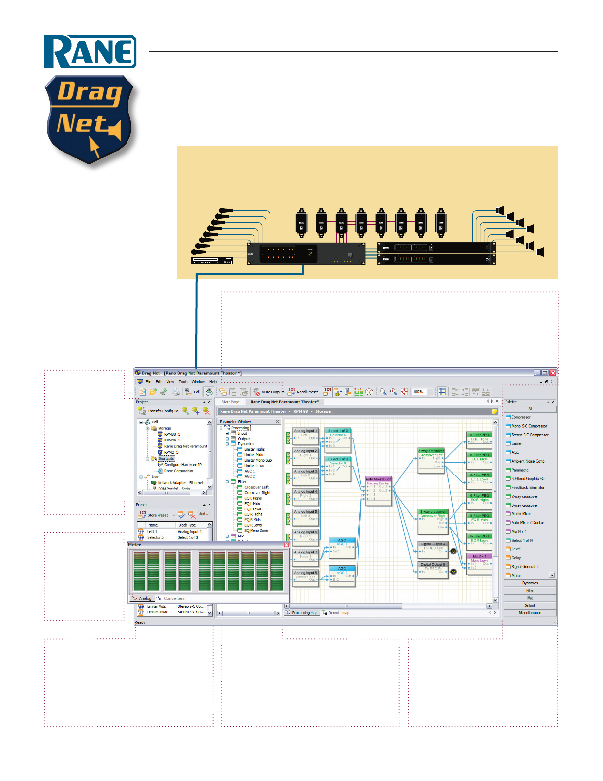
Project window
• Easy project
management for
Drag Net congurations, proposals,
drawings and web
links using the
Shortcuts folder.
• Allows oine
setup at the oce
for later download
into live devices.
Sport Clubs
Retail Stores
Offices
Conferencing
Theme Parks
Malls
Inputs: Up to 8 mic/line plus
AES3 digital (depending on
the RPM model). Daisy-chain
more with AES3 I/O.
Device Configuration window
• What you see is what you get – If a control is shown and DSP usage <100%, use it!
• Multi-select cut/copy/paste and block alignment tools.
• Remotely addressable Level & Preset recall controls.
• Tags on processing blocks display the last recalled preset.
10Base-T Ethernet
• View the Preset elements from the Processing Map or from the Preset block list.
Remotes: End-user Levels
and Presets can be assigned
to Remotes, installed near the
source or inside the zone.
multichanne l ampli ers sold separ atelyRane R PM 88
Outputs: Up to 8 balanced
line outputs plus an AES3
digital output (depending
on the RPM model).
Meter Window
• Consolidates all
input and outputs
into a resizeable
and dockable
meter bridge.
Preset window
• Preset overlay feature allows changing
one, some, or all parameters.
• Settings can be stored in 24 internal,
non-volatile Presets.
• Recall the rst 8 Presets via remote contact closures (see Remote Mapping).
Parameter window
• Displays a tree structure view of all used
signal processing and control blocks.
• Associates parameters to remote controls
(contact closures, Smart Remotes).
• Drag-and-drop into the Preset window
to quickly build Presets.
Palette window
• Lists signal processing blocks
used to create the audio ow.
• Drag and drop blocks from the
Palette to the Device Conguration window to build your
custom audio system.
Drag Net
SOFTWARE
Processing Blocks
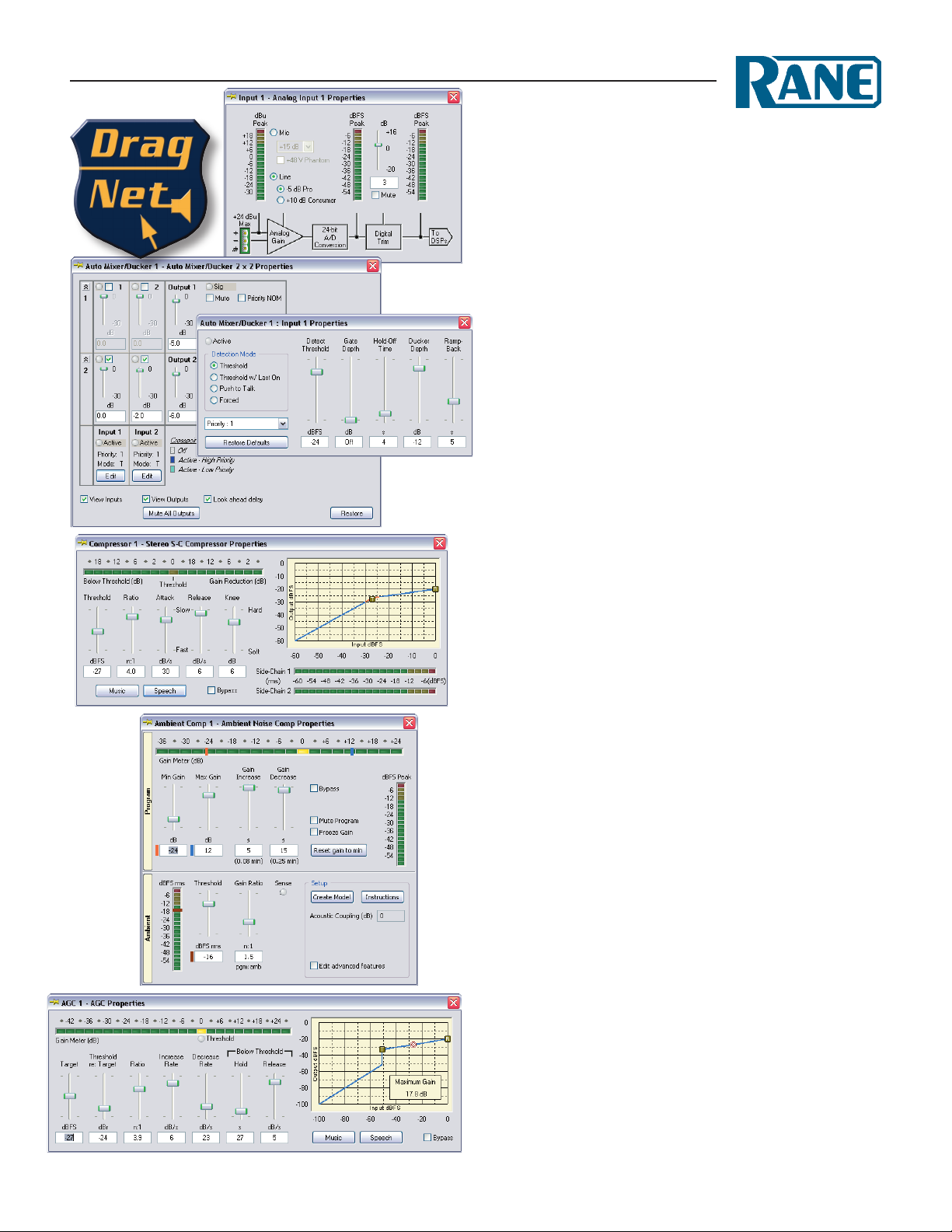
Inputs and Outputs
• Input block features vary depending on RPM hardware.
RPM 88/44/22/2m: mic or line, +48V Phantom Power.
RPM 88/44/22: AES3 digital I/O with sample rate conversion.
RPM 26z: line-level only, analog gain trim.
RPM 2: line-level only.
• Software controlled mic/line Inputs (RPM 88/44/22/2m):
-128 dBu EIN (mic) with +48 VDC Phantom Power.
Coarse Gain from +15 to +60 dB in 15 dB steps.
Fine Trim from +16 to -20 dB in 1 dB steps.
• Line-level Balanced Output Trim maintains highest signal-to-
noise for all gain settings.
• Intuitive gain structure GUI.
Priority Auto Mixer / Ducker
• Advanced music and paging processor, with all the elements for
multi-zone paging and priority program management.
• A variety of In/Out combinations are available, up to 8 x 8.
• Automatic detection of input signal with noise immunity.
• Push-to-Talk operation from VIP Port contact closure.
• Forced on from properties window.
• Cross-point assignment of any input to any output.
• Eight priority levels for each input, arbitrated at each crosspoint.
• Priority based Ducking at each crosspoint.
• Priority dependent NOM mode preserves gain-before-feedback.
Applications:
• Automatic, priority paging with auto detection or Push-to-Talk.
• Automatic, priority based program selection.
• Simple, priority based ducking.
• NOM-based automatic mixing.
More Select and Mix Blocks
Mix N x 1
Select 1 of N
Matrix Mixer
Deluxe Stereo or Mono Side-Chain Compressor
• Smooths out program dynamics, with soft knee adjustment.
• Uses true rms level detection. A side-chain allows lters in the
detector path as well as an input for ducking applications.
• Provides initial default settings for music and speech.
Ambient Noise Compensator
• Automatically boosts program levels to match changes in back-
ground noise level.
• Connect any music or paging source to the Program input, and
the noise sensing microphone to the Ambient input.
Automatic Gain Control (AGC)
• Versatile gain riding block helps maintain the appropriate signal
level and dynamic range for an application.
• Allows transparent control of both speech and music levels.
• Uses a side-chain with true rms level detection, allowing lters
in applications that benet from band-limited detection for
voice or instrument AGC. It is also possible for the detector to
use signals other than the gain-controlled-signal.
Up to 10 inputs / 10 outputs!
}
Processing Blocks
Drag Net
SOFTWARE
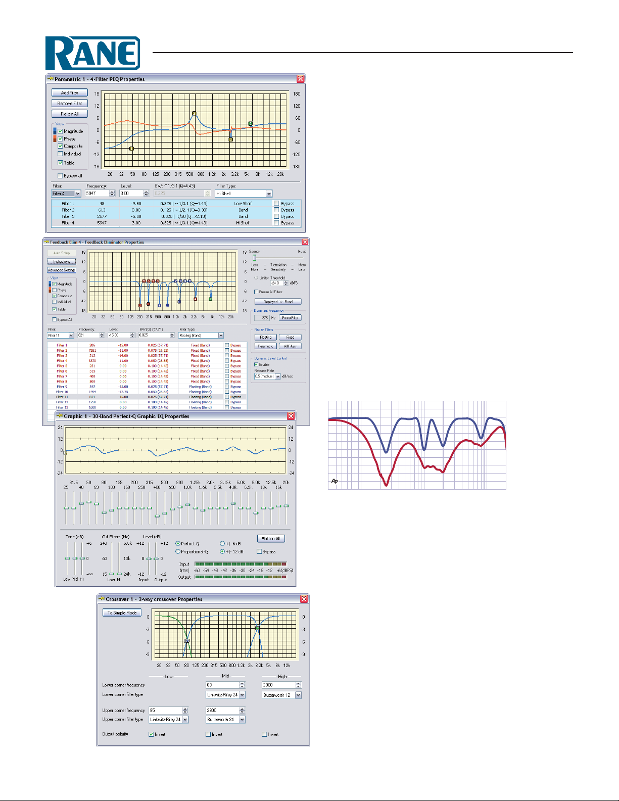
Parametric Equalizer (PEQ)
• Add/Remove Filter feature easily changes the number of lters without deleting the block or recreating settings. Up to 15
lters can be added to each PEQ block. Adjust lter quantities
oine without redrawing blocks and signal ow.
• Each numbered icon in the graph represents an available EQ
lter. ese icons can be selected and dragged about the graph
to adjust the frequency (horizontal) and level (vertical) parameters, or precise values may be entered.
• Separate views for Magnitude, Phase, Composite, and individual lters. Tab display of all lter parameters in list form.
Feedback Suppressor
• 5, 10 & 15 lter versions for optimum use of DSP resources.
• Fixed, oating and user-adjustable PEQ lter types.
• Reset oating lters on power up or user-dened timeout.
• Speech and music modes.
• Auto-setup mode with limiter for fast setup.
• Dynamic level control.
True Response Graphic Equalizer with Perfect-Q™
• Rane’s patent-pending Perfect-Q technology means Drag
Net equalizers have no band interaction, even with drastic
adjustments of adjacent bands (blue line). But you can still
select traditional Proportional Q if desired (red line).
Rane Perfect-Q™
Proportional-Q
2-way or 3-way Crossover
• Adjust crossover frequencies by selecting and dragging the
crossover point icon to a new location, or type in values. Filters may be linked and adjusted simultaneously.
• In Simple Mode, all crossovers are Linkwitz-Riley, 24 dB per
octave.
• Advanced Mode may include any combination of:
Linkwitz-Riley 12 or 24 dB per octave
Butterworth 12/18/24 dB per octave
Bessel 12/18/24 dB per octave
1st-order 6 dB per octave lter.
Additional Processing Blocks
Compressor
Limiter
Delay
Signal Generator
Level
Meter
Text Labels

Drag Net
REMOTES
Remote Controls
Depending on which remote is selected for the application, the
end user is presented easy access to a variety of functions such as
source selection, preset recall, and level adjustment. All remotes
mount in a standard U.S. electrical box with a minimum depth
of 2¼ inches, and covered with a standard Decora® plate cover.
Because of the display width, the SR 3 is the only remote that
can’t t next to itself in a 2-gang electrical box, but will t next
to any other remote.
SR 2
Smart Remote
SR 3
Smart Remote with LCD
Live Remote Mapping
• e Remote Map sets up the assignments, parameters and remote
devices used for control.
• Signal processing parameters (a Source Selector’s Input parameter,
for example) are linked to Remotes by creating Groups. ese
Groups are created by dragging items from the Parameter window
into the Group Assignment section of the Remote Map.
• From the Versatile Input Port, control almost any parameter from
pot-on-a-wall, contact closures, or pre-made Remotes.
• For more control, up to 8 optional Smart Remotes (SR 2, SR 3,
SR 4) can be connected to an RPM unit via the RW 485 Remote
Interface Port.
Smart Remotes
Smart Remotes are compatible with the RPM 88, RPM 44,
RPM 22’s Remote Interface Port, and electrically compatible
with standard RS 485 interfaces.
e various modes and parameters (e.g., Backlight Timer)
are set directly when connected to a live device. Congurations
can be created oine and saved as Storage les or user templates
for subsequent upload to the remote at the job site.
It is possible to assign a single
remote to one or more parameters
– to control a mono or stereo zone
level, for example. It is also pos-
Office
Small Dogs
Medium Dogs
Big Dogs
Chicken Coop
Pig Sty
Horse Barn
Goat Pen
SR 4
Smart Remote with LEDs
sible to assign multiple remotes to
control the same parameter, as in
a primary/secondary arrangement.
Remotes linked in this manner
automatically track each other’s
changes, remaining in synch at all
times.
Smart Remotes require
shielded CAT 5 cable with two
twisted pairs.
LEVEL
VR 2
4
268
0
10
Volume Remote
4
3
2
LRS 4
1
Level Recall Switch
MRS 4
Memory Recall Switch
VIP Remotes
Using any of the RPM series Versatile Input Port (VIP) voltagecontrolled level inputs, the VR 2
provides a simple “pot-on-a-wall”
solution, and the LRS 4 and MRS
4 provide 4-way radio button
“switch-on-a-wall” solutions.
Only three wires are required
for connection.

Drag Net
SOFTWARE
Specifications
Parameter Specification Limit Units Conditions/Comments
Compressor rms detector
.....reshold Range +0 to -40 1 dB ½ dB steps
.....Ratio Range 1:1 to 20:1 plus innity:1 typ 29 steps between 1:1 & 20:1
.....Attack Time 0.5 to 100 typ msec 16 steps †
.....Release Time 1 msec to 5.0 sec typ 15 steps †
.....Gain reduction meter Inverted peak response indicates instantaneous minimum gain setting
Limiter peak detector
.....reshold Range +0 to -40 1 dB ½ dB steps; Ratio xed at innity
.....Attack Time 0.5 to 100 typ msec 16 steps †
.....Release Time 1 msec to 5.0 sec typ 15 steps †
Parametric EQ all except CD Horn EQ
.....Frequency Range 20 to 20,000 typ Hz Minimum step size 1 Hz
Band-pass (Presence) Bandwidth ref. to 3 dB from peak/notch level
.....Filter Level Range +12 to -15 dB ¼ dB steps
.....Bandwidth Range 0.025 to 2.025 oct. Q of 57.71 to 0.66; 80 steps total
Shelving
.....Filter Level Range +12 to -15 dB ¼ dB steps; ±3 dB slope
High cut & low cut
.....Filter type Butterworth 2nd-order
All-pass 1st-order unity gain magnitude response
.....Phase shift -90 Deg. at center frequency
All-pass 2nd-order Bandwidth refers to frequencies where the phase is +90 and -90 degrees with respect to the center
frequency. Maximum phase shift is ±180 degrees.
.....Bandwidth Range 0.025 to 2.025 oct. Q of 57.71 to 0.66; 80 steps total
CD Horn EQ
Frequency Range 2k to 5k typ Hz +3 dB corner freq.; 6 dB/octave slope
Crossover Filter Types
.....Bessel Corner FrequencyAttenuation
.....2nd-order -4.5 dB at selected frequency
.....3rd-order -6.25 dB
.....4th-order -7.5 dB
.....Butterworth corner frequency. -3 dB at selected frequency
.....Butterworth orders 2nd, 3rd & 4th 12, 18 & 24 dB/octave, respectively
.....Linkwitz-Riley corner frequency. -6 dB
.....Linkwitz-Riley orders 2nd & 4th 12 & 24 dB/octave, respectively
.....Crossover frequency range 20 to 20,000 Hz
.....Crossover freq. step size 1 Hz typ
Mix
.....Input Range -30 to 0 dB ½ dB steps plus Mute
.....Output Range 30 to +16 dB ½ dB steps plus Mute
Level
.....Input Range -30 to +16 dB ½ dB steps plus Mute
Delay
.....Delay Range 0 to 500 msec
.....Minimum Step Size 0.02083 msec 48 kHz sampling rate
.....Temperature Range -20º to 120º F deg. -29 to 49 C; 1º F minimum step size
Sine Wave Generator 20 to 20,000 Hz 1 Hz steps
Pink Noise: Type Pseudo Random (average) ½ dB error e phase between individual generators is likely to
be uncorrelated, but not guaranteed.
.....Period 167 typ sec
.....Crest Factor 4.9 typ
Meter: Range 60 dB Peak Response
Minimum System: Pentium 2 PC (266 MHz), 30 MB available disk space, 128 MB R AM, Windows 98(SE), 2000, XP, Vista or 7,
Internet Explorer 6 or higher, 10Base-T capable Ethernet Network Interface Card (NIC)
Recommended System: Pentium 4 PC (>1.5 GHz), 512 MB RAM, Windows XP, Vista or 7.

4
0
268
10
LEVEL
Basic Church System
dB Headroom
dB Headroom
dB Headroom
dB Headroom
3
6
12
24
Limit
1
Comp
Exp
Fault
Load
Ready
3
6
12
24
Limit
2
Comp
Exp
Fault
Load
Ready
3
6
12
24
Limit
3
Comp
Exp
Fault
Load
Ready
3
6
12
24
Limit
4
ON
Comp
Exp
Fault
Load
Ready
MA 4
Rane SR 4 Remote
at Pulpit to
change Levels
and Presets
Lavalier Only
Pulpit Only
Lav and Pulpit
Lav and Choir
Pulpit and Choir
All Mics On
All Mics o
Rapture
Rane RPM 44
Programmable
Multiprocessor
Rane MA 4 Amplier
Wireless
Lavalier
Mic
Wireless Receiver
INPUT
1 2 3 4
-4
-12
-48
OUTPUT
1 2 3 4
-4
-12
-48
Peak dBFS
Low
Low
(100W)
AES3
LOCK
A B
AES3
A B
Pulpit
Mic
-4
-12
-48
-4
-12
-48
Mid
Mid
(100W)
PRESET
High Cry
High
(100W)
Choir
Mic
VIP/VOP RW 485
Choir
Mic
ETHERNET
STATUS POWER
Room
Cry
(100W)
AMPLIFIER
MULTIPROCESSOR
DIGITAL
RPM 44
PROGRAMMABLE
Rane VR 2
Remote
in Cry Room
to change
Level
Main 3-Way Central Cluster Cry / Overow Room

Restaurant System with 10 Zones
Mic
1
Rane RPM 88
Programmable
Multiprocessor
Amplifiers
Six Zones share one of four input
sources: Mic (for meetings); Radio; CD
& MP3/ computer music. A Rane
MRS 4 selects what's heard in these six
zones.
Using two Rane SR 4 remotes (one in
the rack, one at the Host station)
permits independent Level control of
each of these six zones.
Mic
2
CD Changer
INPUT
1 2 3 4 5 6 7 8
-4
-12
-48
OUTPUT
1 2 3 4 5 6 7 8
-4
-12
-48
Dine 1 & 2
DVD Player
Peak dBFS
AES3
LOCK
A B
AES3
A B
Dine 3
XM
Sirius
VIP/VOP RW 485
MP3 from
computer
ETHERNET
STATUS POWER
RPM 88
PROGRAMMABLE
MULTIPROCESSOR
AES3
Satellite /
Radio Tuners
-4
-12
-48
-4
-12
-48
PRESET
To Remotes
Dine 4
Host
Patio Dining
Three more SR 4 remotes, one in each
of the remaining zones, allow
independent source selection & Level
control from within the zone.
Additional Drag Net system examples
can be found in the Applications
section at www.rane.com.
Entry
Kitchen
Bar South
Patio Bar
Bar North

Drag Net
INPUT
AES3 OUTPUT
1 2
A B
1432
6
5
LOCK
VIP POWER
ETHERNET STATUS
RPM 26z
PROGRAMMABLE
MULTIPROCESSOR
PRESET
24
24
INPUT
1 2 3 4
OUTPUT
1 2 3 4
PRESET
RPM 44
A B
A B
Peak dBFS
-4
-12
-48
-4
-12
-48
-4
-12
-48
-4
-12
-48
AES3
AES3
LOCK
PROGRAMMABLE
MULTIPROCESSOR
VIP/VOP RW 485
ETHERNET
STATUS POWER
INPUT
OUTPUT
1 2 1 2
VIP POWER
ETHERNET
STATUS
RPM 2
PROGRAMMABLE
MULTIPROCESSOR
PRESET
24
HARDWARE
RPM 2
RPM 2m
RPM 22
2 line-level analog inputs, 2 analog outputs
1 2
INPUT
1 2
OUTPUT
2 mic/line analog inputs, 2 analog outputs, AES3 output
2 line-level analog inputs, 6 analog outputs, AES3 input
INPUT
1 2
-4
-12
-48
OUTPUT
1 2
-4
-12
-48
Peak dBFS
AES3
A B
A B
MADE IN U.S.A.
RPM 2
RANE CORP.
FOR CONTINUED
GROUNDING
PROTECTION
DO NOT
REMOVE
SCREW
100-240V
20 WATTS50/60 Hz
A B
AES3
MADE IN U.S.A.
RPM 2m
RANE CORP.
FOR CONTINUED
GROUNDING
PROTECTION
DO NOT
REMOVE
SCREW
100-240V
THIS DEVICE COMPLIES WITH PART 15 OF THE FCC RULES FOR A CLASS 'B' COMPUTING DEVICE.
20 WATTS50/60 Hz
MADE IN U.S.A.
RPM 26z
RANE CORP.
FOR CONTINUED
GROUNDING
PROTECTION
DO NOT
REMOVE
SCREW
100-240V
20 WATTS50/60 Hz
LOCK
-4
-12
-48
AES3
-4
-12
-48
COMMERCIAL AUDIO
EQUIPMENT 24TJ
R
ACN 001 345 482
COMMERCIAL AUDIO
EQUIPMENT 24TJ
R
ACN 001 345 482
COMMERCIAL AUDIO
EQUIPMENT 24TJ
R
ACN 001 345 482
DEFAULT
24
PRESET
DEFAULT
DEFAULT
PRESET
24
10Base-T
10Base-T
10Base-T
LINK
LAN
LINK
LAN
LINK
LAN
VERSATILE INPUT PORT
0-5V
1 2 3 4 5 7 6 8
1 2 3 4 5 7 6 8
VIP POWER
ETHERNET STATUS
AES3 OUTPUT
VERSATILE INPUT PORT
0-5V
1 2 3 4 5 7 6 8
1 2 3 4 5 7 6 8
AES3 INPUT OUTPUTS
VERSATILE INPUT PORT
0-5V
1 2 3 4 5 7 6 8
1 2 3 4 5 7 6 8
VIP/VOP RW 485
+5V
100 mA
REF
GND
REF
GND
+5V
100 mA
REF
GND
REF
GND
+5V
100 mA
REF
GND
REF
GND
ETHERNET
STATUS POWER
2 mic/line analog inputs, 2 analog outputs, AES3 input/output
COMMERCIAL AUDIO
EQUIPMENT 24TJ
R
100-240V
RPM 22
MADE IN U.S.A.
RANE CORP.
ACN 001 345 482
FOR CONTINUED
GROUNDING
PROTECTION
DO NOT REMOVE
SCREW
55 WATTS50/60 Hz
DEFAULT LAN
10Base-T
AES3 OUT AES3 IN
LINK
REMOTE INTERFACE PORT
CLASS 2 WIRING
(RW 485)
A B +V -V
A B +V -V
–+
VERSATILE OUTPUT PORT
CLASS 2 WIRING
OPEN COLLECTOR
+40 VDC / 100 mA MAX
1 2 3 4 5 76 8
1 2 3 4 5 76 8
RPM 2m
PROGRAMMABLE
MULTIPROCESSOR
2 1
– + + –
– + + –
– + + –
– + + –
12 2 1
3 4 5 6
– + + – – + + –
– + + – – + + –
RPM 22
PROGRAMMABLE
MULTIPROCESSOR
VERSATILE INPUT PORT
+12 VDC /
100 mA MAX
1 2 3 4 5 76 8
+12
GND
1 2 3 4 5 76 8
+12
GND
0-5V
INPUTSOUTPUTS
++ – – + –
OUTPUTS
– + + –
– + + –
REF
REF
+5 VDC /
100 mA
GND
GND
INPUTS
2 1 2 1
– + + –
– + + –
INPUTSOUTPUTS
2 1
– + + –
– + + –
INPUTS
2 1 2 1
– + + –
– + + –
This device complies with Part 15
of the FCC R ules. Operation is
subject to the following two
conditions: (1) this device may not
cause harmful in terference, and
(2) thi s device must accept any
interference received, i ncluding
interference that may cause
undesired operation.
THIS DEVICE
COMPLIES WITH PART
15 OF THE FCC RULES
FOR A CLASS 'B'
COMPUTING DEVICE.
THIS DEVICE
COMPLIES WITH PART
15 OF THE FCC RULES
FOR A CLASS 'B'
COMPUTING DEVICE.
RPM 44
RPM 88 RPM 26z
4 mic/line analog inputs, 4 analog outputs, AES3 input/output
INPUT
1 2 3 4 5 6 7 8
-4
-12
-48
OUTPUT
1 2 3 4 5 6 7 8
-4
-12
-48
Peak dBFS
COMMERCIAL AUDIO
EQUIPMENT 24TJ
R
AES3
A B
A B
100-240V
AES3
RPM 44
MADE IN U.S.A.
RANE CORP.
ACN 001 345 482
FOR CONTINUED
GROUNDING
PROTECTION
DO NOT REMOVE
SCREW
55 WATTS50/60 Hz
LOCK
-12
-48
-12
-48
DEFAULT LAN
-4
-4
PRESET
24
10Base-T
AES3 OUT AES3 IN
LINK
REMOTE INTERFACE PORT
CLASS 2 WIRING
VIP/VOP R W 48 5
8 mic/line analog inputs, 8 analog outputs, AES3 input/output
REMOTE INTERFACE PORT
LINK
OUTPUTS
(RW 485)
B +V -V
A
B +V -V
A
4 3 2 1
+ – + – + – + –
VERSATILE OUTPUT PORT
CLASS 2 WIRING
OPEN COLLECTOR
+40 VDC / 100 mA MAX
3 4576 8
1 2
3 4576 8
1 2
COMMERCIAL AUDIO
EQUIPMENT 24TJ
R
100-240V
RPM 88
MADE IN U.S.A.
RANE CORP.
8 7 6 5
ACN 001 345 482
+ – + – + – + –
10Base-T
FOR CONTINUED
GROUNDING
PROTECTION
DO NOT REMOVE
SCREW
55 WATTS50/60 Hz
DEFAULT LAN
OUTPUTS INPUTS
34 12 4 3 2 1
–+
(RW 485)
A B +V -V
A B +V -V
+12 VDC /
100 mA MAX
GND
+12
GND REF
+12
ETHERNET
VERSATILE OUTPUT PORT
CLASS 2 WIRING
OPEN COLLECTOR
+40 VDC / 100 mA MAX
1 2 3 4 5 76 8
1 2 3 4 5 76 8
S TA TU S POWER
8 7 6 5
+ – + – + – + –
VERSATILE INPUT PORT
0-5V
3 4576 8
1 2
3 4576 8
1 2
++ – + –– + – + – + – + –
+12 VDC /
100 mA MAX
+12
GND
+12
GND REF
RPM 88
PROGRAMMABLE
MU L TIPROCESSO R
+5 VDC /
100 mA
REF
GND
GND
VERSATILE INPUT PORT
0-5V
1 2 3 4 5 76 8
1 2 3 4 5 76 8
INPUTS
This device complies with Part 15
of the FCC R ules. Operation is
subject to the following two
conditions: (1) this device may not
cause harmful in terference, and
(2) thi s device must accept any
interference received, i ncluding
interference that may cause
undesired operation.
This device complies with Part 15
of the FCC R ules. Operation is
+5 VDC /
subject to the following two
100 mA
conditions: (1) this device may not
REF
GND
cause harmful in terference, and
(2) thi s device must accept any
interference received, i ncluding
interference that may cause
undesired operation.
GND
4 3 2 1
+ – + – + – + –+ – + – + – + –+ – + – + – + –+ – + – + – + –
+ – + – + – + –
AES3 OUT AES3 IN
CLASS 2 WIRING
All RPM units have Ethernet 10Base-T, 8 logic inputs, balanced Euroblock connectors.
For hardware details, see the Data Sheets and Manuals for any of these products, all available at www.rane.com
©Rane Corporation 10802 47th Ave. W., Mukilteo WA 98275-5098 USA TEL 425-355-6000 FAX 425-347-7757 WEB www.rane.com
108359
 Loading...