


INSTALLATION, OPERATING AND SERVICE INSTRUCTIONS RRO SERIES
CAST IRON OIL-FIRED BOILER
9700609
For service or repairs to boiler, call your heating contractor. When seeking information on boiler, provide Boiler Model Number and Serial Number as shown on Rating Label.
Boiler Part Number |
Boiler Serial Number |
Installation Date |
RRO _ |
|
|
Heating Contractor |
|
Phone Number |
|
|
|
Address |
|
|
|
|
|
106630-01 - 3/16

IMPORTANT INFORMATION - PLEASE READ THIS PAGE CAREFULLY
1.Read and understand all instructions, including all those contained in component manufacturers manuals which are provided with the appliance before installing, starting-up, operating, maintaining or servicing this appliance. Keep this manual and literature in legible condition and posted near appliance for reference by owner and service technician.
2.All heating systems should be designed by competent contractors and only persons knowledgeable in the layout and installation of hydronic heating systems should attempt installation of any boiler.
3.All boilers must be installed in accordance with National, State and Local Plumbing, Heating and Electrical Codes and the regulations of the serving utilities. These Codes and Regulations may differ from this instruction manual. Authorities having jurisdiction should be consulted before installations are made.
In all cases, reference should be made to the following Standards:
USA BOILERS
A.Current Edition of American National Standard ANSI/NFPA 31, “Installation of Oil Burning Equipment”, for recommended installation practices.
B.Current Edition of American National Standard ANSI/NFPA 211, “Chimneys, Fireplaces, Vents, and Solid Fuel Burning Appliances”, For Venting requirements.
C.Current Edition of American Society of Mechanical Engineers ASME CSD-1, “Controls and Safety Devices for Automatically Fired Boilers”, for assembly and operations of controls and safety devices.
D.All wiring on boilers installed in the USA shall be made in accordance with the National Electrical Code and/or Local Regulations.
DANGER
DO NOT store or use gasoline or other flammable vapors or liquids in the vicinity of this or any other appliance.
2

WARNING
This boiler is suitable for installation on combustible flooring. Do not install boiler on carpeting.
Installation is not complete unless a pressure relief valve is installed into the tapping located on top left corner of rear section - See Piping and Trim Sections of this manual for details.
This boiler is designed to burn No. 2 fuel oil only. Do not use gasoline, crankcase drainings, or any oil containing gasoline. Never burn garbage or paper in this boiler. Do not convert to any solid fuel (i.e. wood, coal). Do not convert to any gaseous fuel (i.e. natural gas, LP). All flammable debris, rags, paper, wood scraps, etc., should be kept clear of the boiler at all times. Keep the boiler area clean and free of fire hazards.
This boiler needs fresh air for safe operation and must be installed so there are provisions for adequate combustion and ventilation air.
This boiler must be connected to an approved chimney in good condition. Serious property damage could result if the boiler is connected to a dirty or inadequate chimney. The interior of the chimney flue must be inspected and cleaned before the start of the heating season for any obstructions. A clean and unobstructed chimney flue is necessary to allow noxious fumes that could cause injury or loss of life to vent safely and will contribute toward maintaining the boiler's efficiency.
Inspect flueways at least once a year - preferably at the start of the heating season. The inside of the combustion chamber, the vent system and boiler flueways should be cleaned if soot or scale has accumulated.
When cleaning this boiler, do not damage combustion chamber liner and/or rear target wall. If damaged, combustion chamber insulation must be replaced immediately.
This boiler requires regular maintenance and service to operate safely. Follow the instructions contained in this manual. Installation, maintenance, and service must be performed only by an experienced, skilled and knowledgeable installer or service agency.
It is the responsibility of the installing contractor to see that all controls are correctly installed and are operating properly when the installation is completed. Do not tamper with or alter the boiler or controls.
Do not operate unit if any control, switch, component, or device has been subject to water.
Oil Burner and Controls must be checked at least once a year or as may be necessitated.
All boilers equipped with burner swing door have a potential hazard which if ignored can cause severe property damage, personal injury or loss of life. Before opening swing door, turn off service switch to boiler to prevent accidental firing of burner outside the combustion chamber. Be sure to tighten swing door fastener completely when service is completed.
Appliance materials of construction, products of combustion and the fuel contain alumina, silica, heavy metals, carbon monoxide, nitrogen oxides, aldehydes and/or other toxic or harmful substances which can cause death or serious injury and which are known to the state of California to cause cancer, birth defects and other reproductive harm. Always use proper safety clothing,respirators and equipment when servicing or working nearby the appliance.
High water temperatures increase the risk of scalding injury. If this boiler is equipped with a tankless heater for domestic water supply, a flow regulator and automatic mixing valve must be installed properly in tankless heater piping. See Piping and Trim Sections of the manual for details.
3

|
Table of Contents |
|
I. |
General Information...................................................................... |
4 |
II. |
Installation Instructions................................................................ |
8 |
III. |
Indirect Water Heater Piping...................................................... |
19 |
IV. |
System Start-Up.......................................................................... |
20 |
V. |
Operating..................................................................................... |
26 |
VI. |
Maintenance & Service Instructions.......................................... |
31 |
VII. |
Boiler Cleaning............................................................................ |
33 |
VIII. |
Troubleshooting........................................................................... |
35 |
IX. |
Repair Parts................................................................................. |
38 |
X. |
Burner Specifications................................................................. |
44 |
Appendix A - Aftermarket Low Water Cut Off (LWCO).................. |
45 |
|
I. General Information
A.INSPECT SHIPMENT carefully for any signs of damage.
1.ALL EQUIPMENT is carefully manufactured, inspected and packed. Our responsibility ceases upon delivery of crated boiler to the carrier in good condition.
2.ANY CLAIMS for damage or shortage in shipment must be filed immediately against the carrier by the consignee. No claims for variances from,
or shortage in orders, will be allowed by the manufacturer unless presented within sixty (60) days after receipt of goods.
B.LOCATE BOILER in front of final position before removing crate. See Figures 1a and 1b for applicable positioning.
1.LOCATE so that smoke pipe connection
to chimney will be short and direct. BOILER IS SUITABLE FOR INSTALLATION ON COMBUSTIBLE FLOOR. Boiler cannot be installed on carpeting.
2.FOR BASEMENT INSTALLATION, provide a solid base, such as a concrete pad, if floor is not level, or if water may be encountered on floor around boiler.
3.PROVIDE SERVICE CLEARANCE of at least
24” on top of boiler for cleaning flueways. Provide at least 24” clearance from front jacket panel for servicing.
4.For minimum clearances to combustible materials. See Figure 2.
C.PROVIDE AIR SUPPLY AND VENTILATION to accommodate proper combustion. If natural ventilation is inadequate, provide a screened opening or duct from the boiler room to the outside. The opening or duct must be sized so the boiler input will not exceed 4,000 BTUH/Sq. In. of free area. If other air consuming appliances are near the boiler, the air inlet should be larger. Consult respective manufacturers.
4
|
245" |
|
|
|
|
8 |
|
|
'A' |
3 |
|
1421" |
|
|
3 " |
|
|
|
'B' |
4 |
|
5" |
35" |
|
RELIEF VALVE |
|
|||
|
|
|
8 |
21" |
|
|
|
11" SUPPLY |
8 |
|
|
|
|
|
|
|
|
2 |
'C' |
|
FLUE |
|
421 |
|
|
COLLAR |
|
DIA. |
|
|
|
TEMP/PRESSURE |
|
|
|
|
|
GAUGE |
|
FLAME |
|
|
BOILER |
|
|
|
CONTROL |
|
|
OBSERVATION |
|
|
|
|
|
|
|
|
|
PORT |
|
|
|
|
|
|
|
121" |
|
|
|
|
4 |
|
315" |
|
|
|
|
8 |
|
|
|
|
121" RETURN |
|
|
OIL BURNER |
|
|
|
|
W/PRIMARY |
|
|
|
|
CONTROL |
|
|
|
13" |
9" |
|
31" |
|
8 |
|
|
|
|
|
|
|
2 |
|
|
FLOOR |
|
|
|
|
LINE |
|
|
|
|
SEE NOTE 2 |
|
DRAIN VALVE |
FRONT VIEW |
|
11" |
RIGHT SIDE VIEW |
|
BURNER SWING DOOR |
|||
|
|
|
||
|
|
CLEARANCE (OPEN 90°) |
|
|
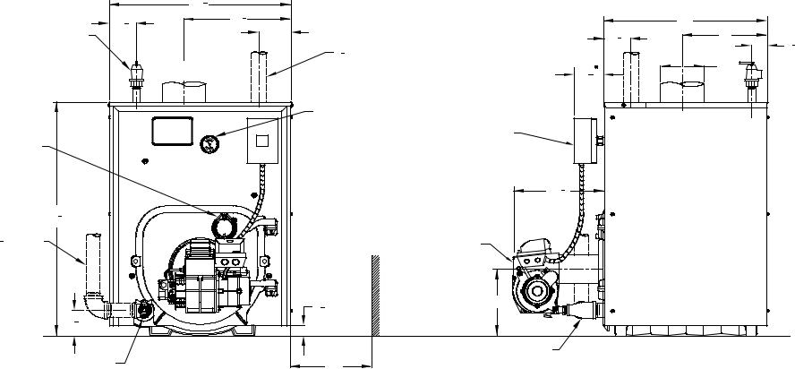
Figure 1a: RRO080 through RRO179 Boiler without Tankless Heater
5
6
|
245" |
|
|
|
|
8 |
|
|
'A' |
3 |
|
1421" |
|
|
3 " |
|
|
|
'B' |
4 |
|
5" |
35" |
|
RELIEF VALVE |
|
|||
|
|
11" SUPPLY |
8 |
21" |
|
|
|
8 |
|
|
|
2 |
|
'C' |
|
FLUE |
|
|
|
|
COLLAR |
|
|
DIA. |
|
|
|
|
|
|
|
TEMP/PRESSURE |
|
BUILT-IN DOMESTIC WATER |
|
|
GAUGE |
|
HEATER W/ 3/4" |
FLAME |
|
61" |
|
CONNECTIONS |
|
|
|
||
OBSERVATION |
|
|
|
|
|
4 |
|
|
|
PORT |
|
|
|
|
|
|
|
|
BOILER |
|
|
|
|
CONTROL |
|
|
|
121" |
|
|
|
|
4 |
|
315" |
|
|
|
|
8 |
|
OIL BURNER |
|
|
|
|
|
||
121" RETURN |
|
W/PRIMARY |
|
|
|
|
CONTROL |
|
|
|
|
13" |
9" |
|
|
|
8 |
|
|
31" |
|
|
|
|
2 |
|
|
FLOOR |
|
|
|
|
|
|
|
|
|
LINE |
|
DRAIN VALVE |
FRONT VIEW |
11" |
SEE NOTE 2 |
RIGHT SIDE VIEW |
|
|
BURNER SWING DOOR |
|
|
|
|
CLEARANCE (OPEN 90°) |
|
|
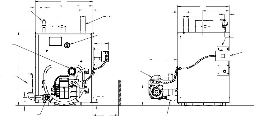
Figure 1b: RRO080 through RRO179 Boiler with Tankless Heater
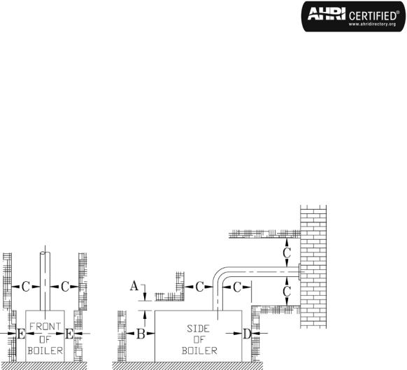
TABLE 1: DIMENSIONAL DATA (See Figures 1a and 1b)
|
|
Dimensions |
|
Approx. Water Content |
Heat Transfer |
Approx. Shipping |
|||
Boiler Model |
|
|
|
|
|
Surface Area |
|||
"A" |
|
"B" |
|
"C" |
(Gallons) |
Weight (LBS.) |
|||
|
|
|
(Sq. Ft.) |
||||||
|
|
|
|
|
|
|
|
||
|
|
|
|
|
|
|
|
|
|
RRO080, RRO092, |
17-3/8" |
8-1/4" |
5-7/8" |
16 |
14.33 |
560 |
|||
RRO120 |
|||||||||
|
|
|
|
|
|
|
|
||
RRO111, RRO151, |
22-3/8" |
10-7/8" |
6-7/8" |
20 |
20.90 |
680 |
|||
RRO179 |
|||||||||
|
|
|
|
|
|
|
|
||
Maximum Working Pressure - Water: 50 PSI |
|
|
|
|
|||||
Boiler shipped from factory with a 30 PSI relief valve. |
|
|
|
||||||
table 2: rating data
Boiler |
Burner Capacity |
Heating |
NET AHRI |
AFUE |
Minimum Chimney Requirements |
||||
|
|
Capacity |
Water Ratings |
|
|
|
|||
Model |
|
|
% |
|
|
|
|||
|
|
Round |
Rectangle |
Height |
|||||
GPH |
MBH |
(MBH) |
(MBH) |
||||||
|
|
||||||||
|
|
|
|
|
|
In. Dia. |
In. x In. |
Ft. |
|
RRO080 |
0.65 |
91 |
80 |
70 |
86.1 |
6 |
8 x 8 |
15 |
|
RRO092 |
0.75 |
105 |
92 |
80 |
86.0 |
6 |
8 x 8 |
15 |
|
RRO120 |
1.00 |
140 |
120 |
104 |
84.3 |
6 |
8 x 8 |
15 |
|
RRO111 |
0.90 |
126 |
111 |
97 |
86.0 |
7 |
8 x 8 |
15 |
|
RRO151 |
1.25 |
175 |
151 |
131 |
85.1 |
7 |
8 x 8 |
15 |
|
RRO179 |
1.50 |
210 |
179 |
156 |
84.0 |
8 |
8 x 8 |
15 |
|
Figure 2: Minimum Installation Clearances To Combustible Materials (Inches)
|
|
C |
|
|
A |
B |
Chimney |
D |
E |
Above |
Front |
Connector |
Rear |
Sides |
6 |
24 |
18 |
6 |
6 |
NOTE 1: Listed clearances comply with American National Standard NFPA 31, Standard for the Installation of Oil Burning Equipment.
NOTE 2: RRO™ Series boilers can be installed in rooms with clearances from combustible material as listed above. Listed clearances cannot be reduced for alcove or closet installations.
NOTE 3: For reduced clearances to combustible material, protection must be provided as described in the ANSI/NFPA 31 standard.
7
II. Installation Instructions
A.REMOVE CRATE
1.Remove all fasteners at crate skid.
2.Lift outside container and remove all other inside protective spacers and bracing. Remove miscellaneous water trim carton.
3.Using hand truck or pipe rollers under skid, move boiler into position along side installation site.
B.REMOVAL OF BOILER FROM SKID
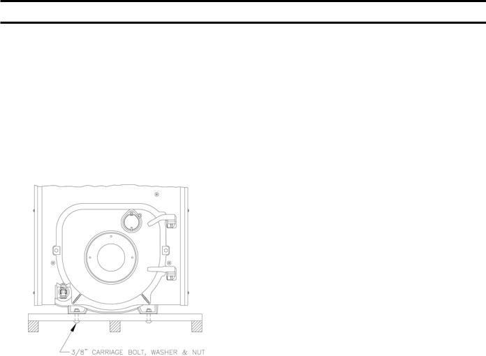
1.Boiler is secured to base with 4 carriage bolts, 2 on left side and 2 on right side. See Figure 3. Remove all bolts.
Figure 3: Removal of Boiler From Skid
2.Tilt boiler to right and to rear. Using right rear leg as pivot, rotate boiler 90° in a clockwise direction, and lower left side of boiler to floor. Tilt boiler and remove crate skid. Care should be exercised to prevent damage to jacket or burner.
C.MOVE BOILER TO PERMANENT POSITION by sliding or walking.
D.INSPECT COMBUSTION TARGET WALL AND COMBUSTION CHAMBER LINER
1.OPEN FLAME OBSERVATION DOOR AND/ OR BURNER SWING DOOR on front of boiler.
Use flashlight to inspect target wall secured to rear section with silastic sealant. Inspect ceramic fiber blanket secured to floor of boiler with water glass adhesive. If either is damaged they must be replaced.
E.INSTALL TRIM AND CONTROLS, AS REQUIRED (see Figure 1a or 1b)
1.Install return piping supplied with boiler. Apply
Teflon or Sealant to all joints prior to assembly.
Thread 1½" NPT x 5" Lg. return nipple into 1½" NPT tapping located in lower left corner of front
section. Thread 1½" x ¾" x 1½" NPT tee onto 5" nipple. Thread ¾" drain valve into ¾" NPT connection on tee. Tighten all joints with wrench
until water tight and 1½" NPT return connection on tee is facing away from boiler horizontally to allow for proper burner swing door clearance, see Figures 1 and 4.
NOTE: Vertical piping will prevent door from opening fully for service and cleaning of boiler.
2.Thread relief valve onto factory installed ¾" NPT x 7¼" nipple located in left rear corner on top of boiler as shown in Figure 1a or 1b. Valve spindle must be in vertical position. Tighten with wrench. Pipe discharge as shown in Figure 4. Installation of the relief valve must be consistent with ANSI/
ASME Boiler and Pressure Vessel Code, Section IV.
F.CONNECT SUPPLY AND RETURN PIPING TO HEATING SYSTEM.
1.CLEARANCES — Hot water pipes shall have clearances of at least ½” from all combustible construction.
2.See Figure 4 FOR PIPING. Also, consult Residential Hydronic Heating Installation and Design I=B=R Guide.
3.Use a boiler water bypass if the boiler is to be operated in a system which has a large volume or excessive radiation where low boiler water temperature may be encountered (i.e. converted gravity circulation system, etc.).
Install a pipe tee between the circulator and boiler return along with a second tee in the supply piping as shown in Figure 4. The bypass should be the same size as the supply and return lines. Locate valves in the bypass and supply outlet as illustrated in Figure 4 for regulation of water flow to maintain higher boiler water temperature.
Set the by-pass and boiler supply valves to a half throttle position to start. Operate boiler until the system water temperature is a normal operating range.
Adjust the valves to provide 180° to 200°F supply water temperature. Opening the boiler supply valves will raise the system temperature, while opening the bypass valve will lower the system supply temperature.
4.If this boiler is connected to heating coils located in air handling units where they may be exposed to refrigerated air the boiler piping must be equipped with flow control valves to prevent gravity circulation of boiler water during the operation of the cooling system.
8
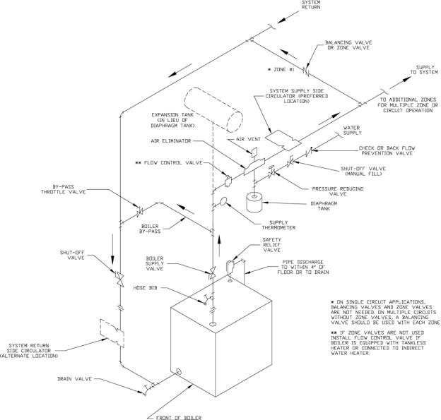
Figure 4: Recommended Boiler Piping for Series Loop Hot Water System
5.If this boiler is used in connection with refrigeration systems, the boiler must be installed so that the chilled medium is piped in parallel with the heating boiler using appropriate valves to prevent the chilled medium from entering the boiler, see Figure
5.Also, consult Residential Hydronic Heating Installation and Design I=B=R Guide.
6.A hot water boiler installed above radiation level must be provided with a low water cutoff device as part of the installation. See Section X, Low Water Cut-Off for additional details.
7.Oxygen Contamination:
a.There are many possible causes of oxygen contamination such as:
i.Addition of excessive make-up water as a result of system leaks.
ii.Absorption through open tanks and fittings.
iii.Oxygen permeable materials in the distribution system.
b.In order to insure long product life, oxygen sources should be eliminated. This can be accomplished by taking the following measures:
i.Repairing system leaks to eliminate the need for addition of make-up water.
ii.Eliminating open tanks from the system.
iii.Eliminating and/or repairing fittings which allow oxygen absorption.
iv.Use of non-permeable materials in the distribution system.
v.Isolating the boiler from the system water by installing a heat exchanger.
See Section VI, Paragraph B for additional details.
9

Figure 5: Recommended Piping for Combination Heating & Cooling (Refrigeration) Systems
CAUTION
Oxygen contamination of the boiler water will cause corrosion of iron and steel boiler components, and can lead to boiler failure. RRO's Standard Warranty does not cover problems caused by oxygen contamination of boiler water or scale (lime) build-up caused by frequent addition of water.
G.CONNECT TANKLESS HEATER PIPING AS SHOWN IN Figure 6. See Table 3 for Tankless Heater Ratings.
Figure 6: Schematic Tankless Heater Piping
THE FOLLOWING GUIDELINES SHOULD BE FOLLOWED WHEN PIPING THE TANKLESS HEATER:
1.FLOW REGULATION — If flow through the heater is greater than its rating, the supply of adequate hot water may not be able to keep up with the demand.
For this reason a flow regulator matching the heater rating should be installed in the cold water line to the heater. The flow regulator should preferably be located below the inlet to the heater and a minimum of 3’ away from the inlet so that the regulator is not subjected to excess temperatures that may occur
Table 3: Tankless Heater Data
Boiler Model |
Rating (Gal/Min) |
Pressure Drop |
|
(PSI) |
|||
|
|
||
RRO080 |
2.75 |
3.9 |
|
RRO092 |
3.00 |
4.7 |
|
RRO120 |
3.25 |
5.6 |
|
RRO111 |
3.25 |
5.6 |
|
RRO151 |
3.75 |
7.2 |
|
RRO179 |
4.00 |
8.0 |
during “off” periods when it is possible for heat to be conducted back through the supply line. The flow regulator also limits the flow of supply water
regardless of inlet pressure variations in the range of 20 to 125 psi.
2.TEMPERING OF HOT WATER — Installation of an automatic mixing valve will lengthen the delivery of the available hot water by mixing some cold water with the hot. This prevents excessive and possibly scalding hot water at the fixtures. In
addition, savings of hot water will be achieved since the user will not waste as much hot water while seeking water temperature to his liking. Higher temperature hot water required by dishwashers and automatic washers is possible by piping the hot water from the heater prior to entering the mixing valve. The mixing valve should be “trapped” by installing it below the cold water inlet to heater to prevent lime formation in the valve.
WARNING
Install automatic mixing valve at tankless heater outlet to avoid risk of burns or scalding due to excessively hot water at fixtures. Adjust and maintain the mixing valve in accordance with the manufacturer's instructions.
3.FLUSHING OF HEATER — All water contains some sediment which settles on the inside of the coil. Consequently, the heater should be periodically backwashed. This is accomplished by installing hose bibs as illustrated and allowing water at city pressure to run into hose bib A, through the heater, and out hose bib B until the discharge is clear. The tees in which the hose bibs are located should be the same size as heater connections to minimize pressure drop.
4.HARD WATER — A water analysis is necessary to determine the hardness of your potable water. This is applicable to some city water and particularly to well water. An appropriate water softener should be installed based on the analysis and dealer’s recommendation. This is not only beneficial to the tankless heater but to piping and fixtures plus the many other benefits derived from soft water.
10
WARNING
Vent this boiler according to these instructions. Failure to do so may cause products of combustion to enter the home resulting in severe property damage, personal injury or death.
Insufficient Combustion Air Supply may result in the production and release of deadly carbon monoxide (CO) into the home which can cause severe personal injury or death.
Improper venting may result in property damage and the release of flue gases which contain deadly carbon monoxide (CO) into the home, which can cause severe personal injury, death, or substantial property damage.
Inspect existing chimney and vent connector for obstructions and deterioration before installing boiler. Failure to clean or replace perforated pipe or chimney liner will cause severe injury or death.
Do not de-rate the appliance. Failure to fire the boiler at it's designed input may cause excessive condensation upon the interior walls of the chimney. In addition, the lower input may not create enough draft to adequately evacuate the by-products of combustion.
H.Chimney Venting
1.Chimney venting is an important part of a safe and efficient oil fired appliance system. Contact your local fire and building officials on specific requirements for restrictions and the installation of fuel oil burning equipment. In addition, consult with
aprofessional knowledgeable on the requirements of NFPA31 – Standard for the Installation of Oil-Burning Equipment and NFPA 211 - Standard for Chimneys, Fireplaces, Vents, and Solid Fuel-Burning Appliances for installations in the United States. Installations in Canada must be reviewed with a professional knowledgeable on the requirements of CSA B139 – Installation Code for Oil-burning Equipment.
2.The safe venting of oil fired boilers is dependant on many factors. Some of these factors include:
a.sufficient draft during the entire heating season to allow for the safe discharge of combustion byproducts and;
b.suitable corrosion protection in the event of condensingfluegases. Onlyatrainedandqualified contractor may install this product.
3.The RRO shall be vented into any of the following:
a.Masonry or metal chimney. Build and install in accordance with local buildings codes; or local authority having jurisdiction; or “Standards
for Chimney, Fireplace, Vents, and Solid Fuel Burning Appliances”, ANSI/NFPA 211 and/or National Building Code of Canada. Masonry chimney must be lined with listed chimney system. Listed clay flue lined masonry chimneys meet venting requirements.
•External chimneys are more susceptible to flue gas condensation due to colder outside air temperatures. To prevent corrosion due to flue gas condensation, use a listed corrosion-resistant metal liner in chimney.
Figure 7: Recommended Smokepipe Arrangement
and Chimney Requirements
•Oversized chimneys are more susceptible to flue gas condensation. To reduce the likelihood of flue gas condensation and ensure proper draft, use a properly sized listed metal liner in oversized chimney.
4.Chimney Inspection – Prior to the installation of any new or replacement fuel burning equipment the chimney shall be inspected by a qualified installer.
The chimney shall be inspected for integrity as well as for proper draft and condensate control. Some jurisdictions require the use of a liner when changing fuel types. Some jurisdictions require the use of a liner even when the same fuel is used. At a minimum, the chimney shall be examined by a qualified person in accordance with the
requirements of Chapter 11 of NFPA 211, Standard for Chimneys, Fireplaces, Vents, and Solid FuelBurning Appliances.
11

a.Loose Mortar – Loose mortar could be an indication of a prior history of condensing flue gases upon the inside walls of the chimney. Colder climates are more susceptible to this condition. Under no circumstances shall a chimney of this condition be used until it meets the requirements of NFPA 211 or CSA B139.
b.Unlined Chimney – Under no circumstances shall a chimney constructed of brick only be used. Only approvedclaylinersorlistedchimneyliningsystems shallbeusedasspecifiedinNFPA31orCSAB139.
c.Abandoned Openings – Openings through the chimney wall that are no longer used shall be sealed in accordance to NFPA 211. Often abandoned openings areimproperly sealedandusuallycovered by a gypsum wall covering.
d.Clean Chimney – Chimney shall be free of all loose debris.
5.Draft Regulator – a draft regulator is not supplied with the boiler. A draft regulator must be used with this appliance. Refer to Figures 7 and 8.
Chimney Connector
1.A chimney connector (vent pipe) is used to connect the boiler to the base of the chimney. The chimney connector should be kept as short as possible. The horizontal length of the chimney connector shall not be greater than 10 feet.
DANGER
The chimney and connector shall be inspected annually for signs of debris and corrosion. Loose mortar at the base of the chimney may be a sign of condensate damage to the chimney. A chimney professional shall be contacted immediately to examine the damage and recommend a solution. Long term operation while in this condition may cause a venting failure and force flue gases into the living space. If the chimney is to be re-lined use the recommendations in NFPA 31, Appendix E or CSA B139.
2.Vent Connector shall be any of the following and of the same size as the outlet of boiler.
a.Type L or a factory built chimney material that complies with the Type HT requirements of ANSI/UL 103. Install in accordance with listing and manufacturer’s instructions.
b.Steel pipe having resistance to corrosion and heat with a minimum wall thickness of 24 Gauge (0.024”).
Figure 8: Proper and Improper Locations of Draft Regulator
12

DANGER
Any signs of condensate seepage at the base of the chimney shall be inspected immediately. The discoloration may be a sign of chimney damage and must be remedied immediately.
Draft
1.The natural draft generated through a chimney is dependent on several factors including, chimney height,temperatureoffluegases,crosssectionareaof chimney,chimneywallinsulationvalue,dilutionairand total volume of flue gases, to name a few. Make sure that the boiler has been running for at least 5 minutes before measuring the draft.
2.Minimum Draft Overfire – The draft induced by a chimney must create at least a pressure of -0.02 inches water column (“ w.c.). The pressure at the canopy cannot be positive since this could create a condition that allows flue gas by-products to escape from the draft regulator. A negative pressure reading up to -.03 inches water column is acceptable for proper operation.
Stack Temperature
1.Thetemperatureofthefluegaseshasasignificanteffect on the amount of draft created in a vertical chimney as well as the propensity to create condensate. The higher the stack temperature, the greater the amount of draft that can be generated. A lower stack temperature not only reduces the amount of draft that can be created but it also increases the possibility that the flue gases could condense in the chimney connector or stack.
2.NFPA 31 and CSA B139 have information to help the installer make an appropriate choice of venting materials. Insomecasesachimneymayhavetobelined to create sufficient draft. In other cases, the chimney may have to be lined to prevent the corrosion of a masonry chimney. Consult with a chimney specialist knowledgeable on the requirements for chimney requirements in your area.
CAUTION
Any doubt on the condition of a chimney or it’s abilitytopreventthegenerationandaccumulation of flue gas condensate, must be relined according to NFPA 31 (United States) or CSA B139 (Canada).
CAUTION
Use the chimney venting tables as a guide. It is highly recommended that any borderline application should result in the relining of the chimney with a suitable liner that creates sufficient draft and to protect against corrosion caused by flue gas condensate.
I.INSPECT NOZZLE, ELECTRODES INSERTION DEPTH AND TURBULATOR SETTING/CHANGE FIRING RATE:
1.Select the proper oil nozzle for the installation. Refer to Table 2 for Firing rates.
If the installed firing rate is desired, inspect the installed nozzle and assure that the nozzle is the correct size and type as specified in Burner Specifications, Table 13 in Section X.
If a different firing rate is desired, remove the nozzle which was factory installed. Locate the desired firing rate nozzle (supplied with burner). Confirm the nozzle is the proper size and type for the desired firing rate as specified in Table 13 in Section
X. Install the proper nozzle in the burner nozzle adaptor.
2.Check the settings and to change the nozzle to a different firing rate:
a.Loosen two (2) igniter latching screws, rotate tabs and swing open igniter about hinge.
b.Loosen knurled nut and disconnect copper connector tube.
c.Remove nozzle line electrode assembly.
d.If installed firing rate is desired, confirm the nozzle is the proper size and type, refer to Table 13 in Section X, then proceed to Item i. below.
e.If a different firing rate is desired, remove the nozzle that was factory installed.
f.Remove Beckett MB(L1) or MD(V1) head.
g.Locate the desired nozzle. Refer to Table 13 in Section X for proper nozzle. The nozzle must be securely installed to assure leak free joints between the nozzle and adapter. When installing the nozzle, be careful not to bump or move the burner electrodes.
Note: On the RRO080 with firing rate of 0.65 GPH, the low firing rate baffle is required.
h.Reinstall Beckett MB(L1) or MD(V1) Head.
i.Inspect and measure burner electrodes. Refer to Figure 9 or the proper electrode setting. Readjust electrode setting to the proper dimensions if necessary. Refer to Figure 9.
j.Reinstall nozzle line electrode assembly.
k.Connect copper connector tube.
l.Inspect Beckett head setting on left side of burner by insuring the line on the label MB(L1) or the blue line MD(V1) are aligned, readjust if necessary. Refer to Figure 9.
m.Tighten knurled nut.
n.Swing igniter closed, rotate tabs and tighten two
(2) igniter screws.
o.Locate the Conversion Label Envelope with the desired firing rate in the Instruction Assembly
Envelope. Apply the Conversion Rating Label
13

Figure 9: "L1" and "V1" Head Electrode Positioning and Gun Setting (Beckett AFG)
near the existing Rating Label on the boiler. DO NOT REMOVE or COVER-UP the existing Rating Label.
J.FUEL UNITS AND OIL LINES
SINGLE-PIPE OIL LINES Standard burners are provided with single-stage 3450 rpm fuel units with the by-pass plug removed for single-pipe installations.
The single-stage fuel unit may be installed single-pipe with gravity feed or lift. Maximum allowable lift is 8 feet. See Figure 10.
Figure 10
14
IMPORTANT
Single-pipe installations must be absolutely airtight or leaks or loss of prime may result. Bleed line and fuel unit completely.
TWO-PIPE OIL LINES For two-pipe systems where more lift is required, the two-stage fuel unit is
recommended. Table 4 (single-stage) and Table 5 (twostage) show allowable lift and lengths of 3/8-inch and 1/2-inch OD tubing for both suction and return lines. Refer to Figure 11.
Be sure that all oil line connections are absolutely airtight. Check all connections and joints. Flared fittings are recommended. Do not use compression fittings.
Open the air-bleed valve and start the burner. For clean bleed, slip a 3/16" ID hose over the end of the bleed valve and bleed into a container. Continue to bleed for 15 seconds after oil is free of air bubbles. Stop burner and close valve.
table 4: single stage units (3450 rpm) two pipe systems
|
Maximum Length of Tubing |
|
Lift "H" |
"H" + "R" (See Figure) |
|
(See Figure) |
3/8" OD |
1/2" OD |
|
Tubing (3 GPH) |
Tubing (3 GPH) |
0' |
84' |
100' |
1' |
78' |
100' |
2' |
73' |
100' |
3' |
68' |
100' |
4' |
63' |
100' |
5' |
57' |
100' |
6' |
52' |
100' |
7' |
47' |
100' |
8' |
42' |
100' |
9' |
36' |
100' |
10' |
31' |
100' |
11' |
26' |
100' |
12' |
21' |
83' |
13' |
--- |
62' |
14' |
--- |
41' |
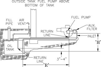
table 5: two-stage units (3450 rpm) two-pipe systems
|
Maximum Length of Tubing |
|
Lift "H" |
"H" + "R" (See Figure) |
|
(See Figure) |
3/8" OD |
1/2" OD |
|
||
|
Tubing (3 GPH) |
Tubing (3 GPH) |
|
|
|
0' |
93' |
100' |
2' |
85' |
100' |
4' |
77' |
100' |
6' |
69' |
100' |
8' |
60' |
100' |
10' |
52' |
100' |
12' |
44' |
100' |
14' |
36' |
100' |
16' |
27' |
100' |
18' |
--- |
76' |
Figure 11
K.SINGLE ZONE WIRING
1.120 Volt Wiring - The boiler should be provided with its own 15A branch circuit with fused disconnect. All 120 volt connections are made inside the HydroStat relay as follows (see Figures 11a and 11b).
•Hot (“black”) - Wire Nut with Black wire of ON/
OFF Toggle Switch
•Neutral (“white”) - Terminal “L2”
•Ground (“green” or bare) - Ground screw on the case
2.Thermostat Wiring - Follow thermostat manufacturer instructions. To insure proper thermostat operation, avoid installation in areas of poor air circulation, hot spots (near any heat source or in direct sunlight), cold spots (outside walls, walls adjacent to unheated areas, locations subject to drafts). Provide Class II circuit between thermostat and boiler. Connect thermostat wire leads to terminals “T” and “T” (see Figures 11a and 11b).
15
 Loading...