

Page 1
WEATHER SATELLITE
RECEIVER ANTENNA
Ramsey Electronics Model No. WSR-ANT
Now you can bring in those hard to get satellites without
the need of an automated antenna, or having to run up
on the roof! This circularly polarized antenna will allow
you to receive a satellite from horizon to horizon without
repositioning! A perfect match for our WSR-1 Weather
Satellite Receiver.
• Made from PVC pipe for durability and weather proofing
• Turnstile antenna for horizon to horizon reception with a
clear picture and no repositioning!
• All parts included for antenna
• Details given on how to mount antenna on a stand or
chimney
• Clear concise manual, easy to follow and assemble
• Troubleshooting guide to help you with any problems
• WSR-LNA recommended with this project.
• Will work for any weather satellite receiver, but designed
with the WSR-1 in mind.
Page 2

RAMSEY TRANSMITTER KITS
• FM-10 FM Stereo Transmitter
• FM-1,2,3,4 FM Wireless Microphones
• PB-1 Telephone Transmitter
RAMSEY RECEIVER KITS
• FR-1 FM Broadcast Receiver
• AR-1 Aircraft Band Receiver
• SR-1 Shortwave Receiver
• AA-7 Active Antenna
• SC-1 Shortwave Converter
RAMSEY HOBBY KITS
• SG-7 Personal Speed Radar
• SS-70 Speech Scrambler
• TG-1 DTMF Tone Grabber
• SP-1 Speakerphone
• MD-3 Microwave Motion Detector
• PH-10 Peak hold Meter
• LC-1 Inductance-Capacitance Meter
RAMSEY AMATEUR RADIO KITS
• FX Series VHF and UHF Transceivers
• HR Series HF All Mode Receivers
• QRP Series HF CW Transmitters
• CW-700 Micro Memory CW Keyer
• PA Series VHF and UHF Power Amplifiers
• Packet Computer Interfaces
• QRP Power Amplifiers
RAMSEY MINI-KITS
Many other kits are available for hobby, school, Scouts and just plain FUN.
New kits are always under development. Write or call for our free Ramsey
catalog.
Ramsey Electronics publication No. MWSR-ANT Revision 1.0
WSR-ANT KIT INSTRUCTION MANUAL
First printing: March 1995
E
C
L
M
A
S
E
Y
E
T
R
O
N
I
C
S
R
B
e
s
t
k
i
t
b
u
i
l
d
n
i
e
s
r
d
l
r
o
w
e
h
t
COPYRIGHT 1995 by Ramsey Electronics, Inc 793 Canning Parkway, Victor, New York
14564. All rights reserved. No portion of this publication may be copied or duplicated without the
written permission of Ramsey Electronics, Inc. Printed in the United States of America.
WSR-ANT • 2
Page 3

Ramsey Publication No. MWSR-ANT
Price $5.00
KIT ASSEMBLY
AND INSTRUCTION MANUAL FOR
WSR-ANT SATELLITE
ANTENNA KIT
TABLE OF CONTENTS
Introduction to the WSR-ANT ...... 4
Pipe Diagram .............................. 6
Wiring Diagram ........................... 7
Parts List ..................................... 8
Notes on Assembly ..................... 9
Assembly Steps .......................... 10
Mounting Ideas ........................... 14
Building a Stand .......................... 14
Chimney Mounting ...................... 16
Troubleshooting Guide ................ 17
Other Information ........................ 17
WSR-ANT • 3
Page 4

Introduction to the WSR-ANT Kit
Receiving a weather satellite is not as easy as it seems. There are
many factors involved in getting a clear picture during the whole
length of the transmission. The primary problem is that the
satellites do not transmit very strong signals, and the signals are
polarized as well. In many cases people will use a directional
antenna and point it directly at the satellite as it passes overhead
using computer software to help guide them.
There are several different antenna types used to receive
satellites. Many satellites are received using dishes such as what
you use for television transmissions. We can’t do that in our case
due to the frequency of the transmission from the satellite.
There are several considerations when deciding what antenna to
use with your WSR-1. As with almost everything there are some
sacrifices to be made with each gain. Here are a few ideas, pros
and cons that you can go by when choosing a suitable antenna.
The crossed Yagi antenna is a popular form of antenna for polar
orbiting satellite reception. This antenna is about the size of a TV
antenna, has greater gain, yields stronger signals, and must be
aimed towards the satellite as it passes. This requires two
rotators, such as TV antenna rotators, to move the antenna in both
elevation (altitude) and azimuth (bearing).
The satellite tracking software used for timing the rise and set of
the satellites will also give you the information you need to track
the satellite in azimuth (from 0 to 360 degrees) and elevation (0 to
90 degrees). The antenna is often "pointed" manually using the
rotator controls located near the receiver. This means that
automatic, unattended recording cannot be done without
additional equipment. More sophisticated systems use a computer
to track the satellite with software and a controller interface to the
antenna rotators. The advantage of this type of antenna setup is
that low satellite passes of high image quality can be easily
recorded. Satellites only a few degrees above the horizon can
WSR-ANT • 4
Page 5

often be recorded with very little noise. This allows a full, high
quality pass, nearly horizon-to-horizon to be recorded with the
NOAA satellites, a picture 2940 miles long by about 1875 miles
wide, it comes to over 5.5 million square miles with a resolution of
2 to 3 miles (in the center of the pass). For a receiver in Florida
that means a picture from the northern part of South America to
Hudson Bay! In addition, because of the narrow beam width,
extraneous noise sources often do not interfere with the satellite
signal.
The disadvantages of a controllable Yagi are complexity, higher
maintenance, and cost. Many users find that the stationary
turnstile antenna is very adequate for their needs.
Another practical type of antenna is the volute VHF antenna. It
looks like a twisted set of wire, but it is quite effective for receiving
satellites, since it doesn’t have as many nulls and peaks due to
polarization of RF signals. These are tough to assemble out of
household equipment and it is very difficult to bend the wires
‘perfectly’, but are widely available through weather satellite
companies.
TV transmissions and GEO synchronous satellites transmit in the
microwave region, making a dish an effective solution for clear
reception. Dishes are very directional, and have plenty of gain at
these frequencies. The satellites that this antenna is designed for
operate in the VHF band, making the size of the required dish
impossibly large for good gain and directionality.
Since we didn't want you to have to go through the expense of an
automated antenna system that can rotate on two axes, or the
trouble of tracking a satellite manually, we came up with a simple
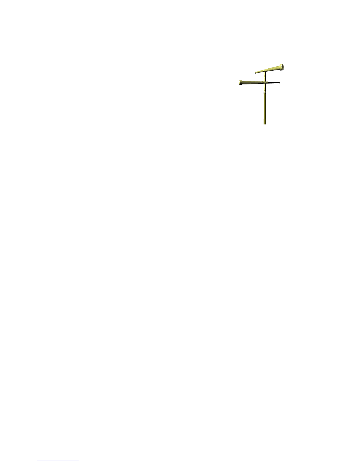
solution. The antenna we have chosen is called a turnstile
antenna, and has the characteristics that we require. This antenna
is directional in the upward direction to receive signals in the sky.
The antenna is circularly polarized as well, just like the weather
satellites, and makes for better reception.
WSR-ANT • 5
Page 6
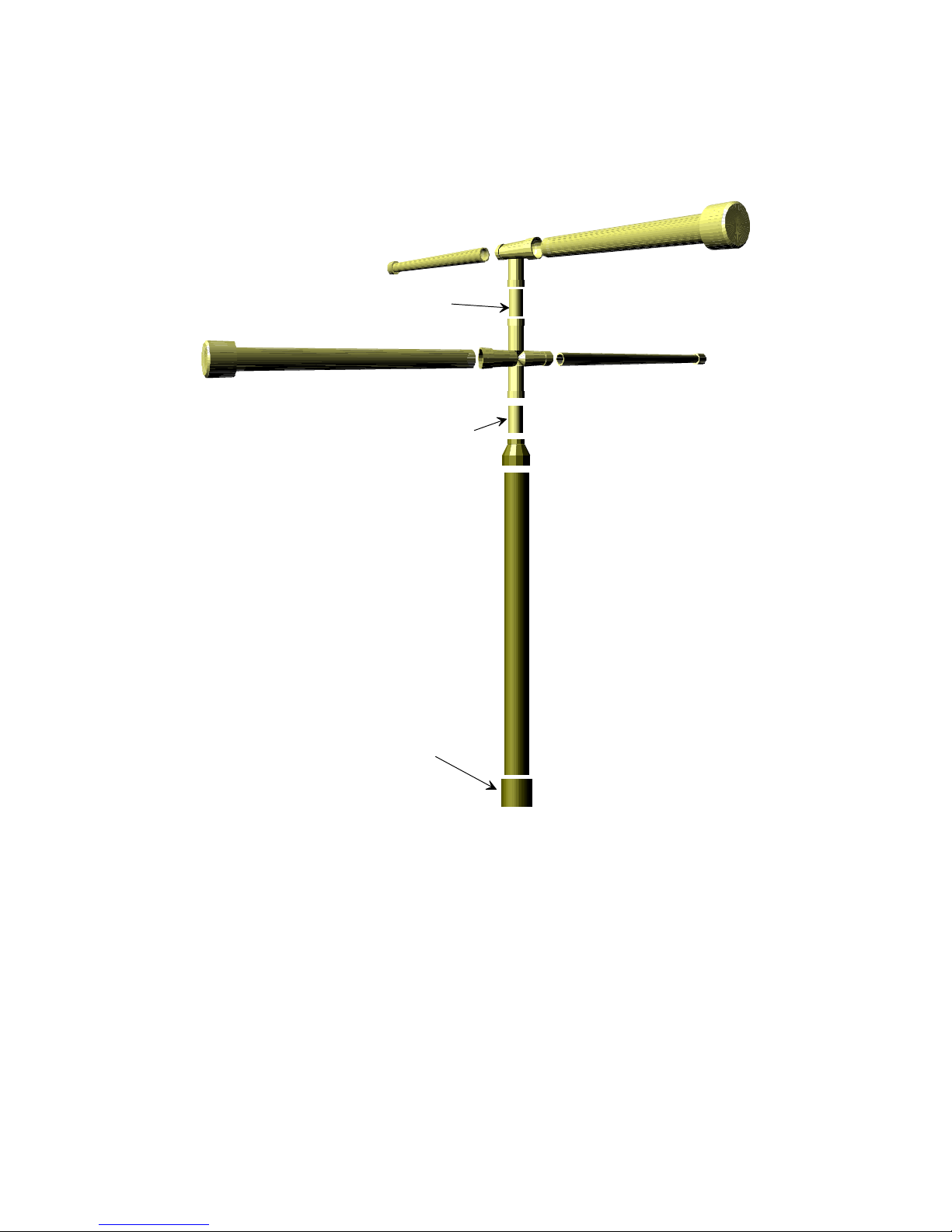
Element 1, 1" x 23 1/2"
1" x 1 3/4" seperator
Element 2, 1" x 23 1/2"
Reflector 1, 1" x 23 1/2"
1" x 2 1/2" seperator
1 1/2" Endcap
Reflector 2, 1" x 23 1/2"
1 1/2" to 1" Reducer
1 1/2" x 24" Base
WSR-ANT • 6
Page 7

WSR-ANT • 7
Page 8

WSR-ANT Parts List:
PVC Pipe
❒ 1, 23 1/2” long 1 1/2” diameter PVC pipe
❒ 4, 23 1/2” long 1” diameter PVC pipe
❒ 1, 2 1/2” long 1” diameter PVC pipe
❒ 1, 1 3/4” long 1” diameter PVC pipe
PVC Pipe parts
❒ 4, 1” PVC endcaps
❒ 1, 1 1/2” PVC endcap
❒ 1, 1x1x1x1 PVC ‘X’ connector
❒ 1, 1x1x1 PVC ‘T’ connector
❒ 1, 1 1/2x1 PVC reducer
COAX Cable
❒ 1, 27” piece of RG58U 50 ohm coax cable
❒ 1, 14 1/8” piece of RG62 75 ohm coax cable
Miscellaneous
❒ 4, 21” pieces of stiff buss wire
❒ Mounting hardware for ‘F’ connector
Optional, not required
❒ WSR-LNA or other preamp that fits within 1 1/2” PVC
Stuff required for assembly
❒ PVC Glue (available at any hardware store)
❒ PVC cleaner or semi fine sandpaper (any hardware)
❒ Thin Rosin Core Solder (Radio Shack #RS64-025)
❒ X-ACTO knife, or razor blade
❒ Needle Nose Pliers (Radio Shack #RS64-1844)
❒ Small diagonal cutters (Radio Shack #RS64-1845)
❒ Soldering iron (Radio Shack #RS64-2072)
❒ Mounting hardware for permanent setup (See text)
❒ Patience
WSR-ANT • 8
Page 9

Notes on assembling your WSR-ANT
There really isn’t a heck of a lot involved with the assembly of this
kit, as you will see. Several pieces of pipe, some wire, and a little
willingness to read directions is all that is required. You will
definitely want to follow each step one at a time, checking it off as
we go. This will prevent us from performing a step out of order,
and assembling something that can’t be undone.
DO NOT! glue any of the PVC together unless the manual tells
you to until you have tested your antenna for proper operation.
Since the antenna is polarized, this means it can receive signals
that are polarized in the same direction as itself. If we accidentally
reverse two of our connections, the polarization is reversed as
well as the directionality, and we will be looking at the ground
instead of the sky. No, you can’t receive pictures of Russia that
way.
The solution to the problem for directionality is to twist the top or
bottom dipole 180 degrees, and the solution for polarization is the
same. A problem occurs if you have already glued everything
together! You won’t be able to correct the problem, unless you rip
the whole thing apart. Let us tell you now, it is not fun.
So off we go into the world of antenna building, and if you need
any assistance in final appearance, look at the diagrams on the
previous two pages for reference. Good luck!
WSR-ANT • 9
Page 10

Assembly Steps
❒ 1. OK, first things first. Find the buss wire that we have
supplied with your kit. This is the thick, silver, stiff wire. Cut this
piece (if not already cut for you) into four pieces 21 inches long.
Set these aside.
❒ 2. Locate the four pieces of 1” x 24” PVC pipe, as well as the
four end caps. You can glue one end cap onto each of the four
1” x 24” PVC pipes.
Gluing PVC for best strength and to be water proof is not as easy
as it seems. There is more to it than just simple pouring on of the
glue and slapping it all together. If there is any grease or dirt on
the PVC while you are gluing, the area will become a potential
spot for the elements to get inside, destroying your antenna over
time. Use semi-fine sandpaper to clean the areas that are to be
glued together before applying glue. You can also use specialized
cleaning agents which are also available in any hardware store.
After the pipe is cleaned, you will want to apply an ample amount
of glue. Go ahead and glob it on. If it is dripping, the quantity of
glue is good. A thin film of glue will lead to gaps which can also be
a path for the elements.
❒ 3. Locate the 1 1/2” x 24” piece of PVC pipe and the 1 1/2” to
1” reducer. Glue these two pieces together.
❒ 4. Glue the 2 1/2” long pipe pieces into the other end of the
reducer.
❒ 5. Glue the 1 3/4” piece of pipe into one of the legs of the ‘X’
joint. (doesn’t matter which leg)
Now we are going to do some wiring with coax cable. Take your
time stripping this cable as you don’t want shorts or opens after
you have glued everything together.
WSR-ANT • 10
Page 11

Stripping Coax cable for soldering
❍ 1. Make a slice using a sharp knife 3/4 inch back from the end of the
wire. Be careful not to cut through the wire underneath the insulation.
❍ 2. Pull the outer piece of insulation off, exposing the first layer of
shield wires.
❍ 3. Pull all of these strands off to one side, then twist them together. If
you want at this point, you may solder these strands together.
❍ 4. Using your sharp knife again, cut a slice around the inner
insulation about 3/8 inch back from the end of the wire.
❍ 5. Pull the insulation off, and twist the wires together.
❍ 6. You can now solder all of your connections
❒ 6. You will want to perform the above process for both ends of
the RG-58U and the RG-62. It is important that the lengths of
the wires that are given to you remain the same as what is
provided, as changing the lengths will decrease the
performance of your project.
❒ 7. If you are planning on using the WSR-LNA preamp, you will
need to solder one end of the RG-58U cable to the end of the
board marked ‘ANT’. Use a spare piece of uninsulated wire to
‘strap down’ the shield of the coax to the preamp PC board.
WSR-ANT • 11
Page 12

❒ 8. Cut the excess ground braid off so that
there aren’t any stray wires.
❒ 9. Thread the other end of the coax through
the 1 1/2” PVC pipe with the reducer, starting
at the 1 1/2 inch end, and exiting at the 1”
end. The LNA board should fit snugly inside
of the PVC pipe. You can use a sock or rag to
temporarily stuff in the pipe to hold things in place while your
working. Make sure and give yourself enough wire to work with
on the exiting end.
❒ 10. Using the diagram on page 7 as a guide, solder the center
conductor of the RG-58U to the center conductor of the RG-62.
❒ 11. Solder one end of a 21” piece of buss wire to the center
conductor joint as well.
❒ 12. Solder the two outside shield wires on the connected
cables together.
❒ 13. Solder another piece of 21” wire to the outside shield wires
for the other half of your lower reflector dipole.
❒ 14. At this point the outer shield and the center conductor
should not be connected together in any way. Check this out
with an ohm meter if you need to; it shouldn’t be less than 1
Meg ohms.
❒ 15. Use the ‘X’ connector for this step. Thread the unused end
of the RG-62 through the opposite opening of where you
mounted the 2 1/2” pipe piece, and then on through the pipe
piece.
❒ 16. Thread the two dipole wires through the two remaining
holes. Make sure the wires don’t touch or cross over inside of
the ‘X’ connector.
❒ 17. On the free end of the RG-62, solder one 21” piece of wire
to the center conductor.
❒ 18. Solder the other 21” piece of wire to the outer shield wire of
WSR-ANT • 12
Page 13

the RG-62.
❒ 19. Thread the RG-62 and its two wires through the base of the
‘T’ and the two wires should come out opposite ends of the ‘T’.
❒ 20. Again make sure that the wires aren’t shorted together
inside the pipe. Use an ohmmeter or continuity checker for this.
❒ 21. Now we want to slide the ‘T’ onto the 2 1/2” piece of pipe
that is attached to the ‘X’. This may be a little tricky since the
RG-62 coax is longer than the pipe. You may have to stuff
some rags into the pipe to hold the wire where you want it so it
doesn’t shove the dipoles down the central pipe. You can also
fold the wire inside of the pipe if you have nimble fingers. DO
NOT GLUE YET!
❒ 22. Straighten out your dipoles and slide the 23 1/2” pipe
assemblies over each of the four dipoles. The straighter you
make the dipoles inside these pipes, the better. Orient the
dipoles so that they cross one another (see page 6).
❒ 23. You can glue each of these dipole ‘arms’ into their
respective pipe joints.
❒ Things should look pretty good at this point. We are almost
finished. Check the diagram on page 6. Compare your antenna
with the one in the diagram for any mistakes.
❒ 24. Now you can pull the rag and the LNA down to the base of
the 1 1/2” pipe.
❒ 25. At this point, if you’re sure that your LNA works, you can
find a way of securely mounting it at the end of the pipe. You
can use a screw through a hole drilled in the pipe to pin the
board within the pipe, or glue it into place using silicon sealant,
or rely on the connector hardware to do the job.
❒ 26. Use the 1 1/2” endcap with the hole drilled in it. Guide the
LNA’s jack through the hole. Use mounting hardware to secure
the jack to the pipe. Press fit the endcap on.
WSR-ANT • 13
Page 14

Mounting Ideas
There are many ways of mounting this antenna, and a few things
have to be taken into account when doing so. First and foremost,
STAY AWAY FROM POWER LINES! They can not only induce
noise into your system, they can also turn you into BBQ. Since we
appreciate your business, try and mount your antenna away from
power lines.
Next, you’ll want to mount it where you can get at it easily. The
roof is the most simple. Trees should be avoided if possible, since
climbing them with an antenna is difficult at best.
You will want to mount your antenna as high as possible, so that
there are no obstructions on the horizons. The problem is that the
higher you mount it, the more likely it will become a target for ten
million volts at 100,000 Amps (lightning). Needless to say, the
LNA, the WSR-1, and your coax cable were not designed to power
New York City. Consider lightning protection if it is within your
budget, or make sure there is a higher conductive object nearby
like a tree, or even the peak of your house. Of course you could
also take your chances and keep a fire extinguisher on hand
during storms.
The general idea is to use common sense in locating the perfect
spot for your antenna, and somewhere near the chimney is usually
the best place. Of course if you have a tower, there is no need for
you to think twice.
There are several ways of mounting this system. We give two
examples to get you started, the first being an all PVC stand. It
uses 1 1/2” diameter PVC to match the lower part of your WSRANT.
Building a PVC stand
The three legs are first capped off at one end, then filled with
either self hardening plaster (for making molds), concrete, or even
WSR-ANT • 14
Page 15

wax. This is for added weight so the wind won’t blow it over. This
is also the reason we use thick walled PVC pipe.
The 30 or 60 degree pipe joints are used to angle the legs out like
a tripod. The center pipe joint has a hole drilled in it for the coax to
pass through. Make sure and seal this hole with sealant before
completion.
The ‘X’ joint holds the antenna mast in place as well as all three
legs. You will also need 3, 2 1/2” long pieces of pipe to join the 30
or 60 degree pipe joints to the ‘X’. Glue the center leg in place, but
don’t glue the outer two until you have leveled the antenna in your
mounting place. The angle of the roof can be compensated for in
this manner. Glue these last, and then wait for the glue to dry
before standing up.
WSR-ANT • 15
Page 16
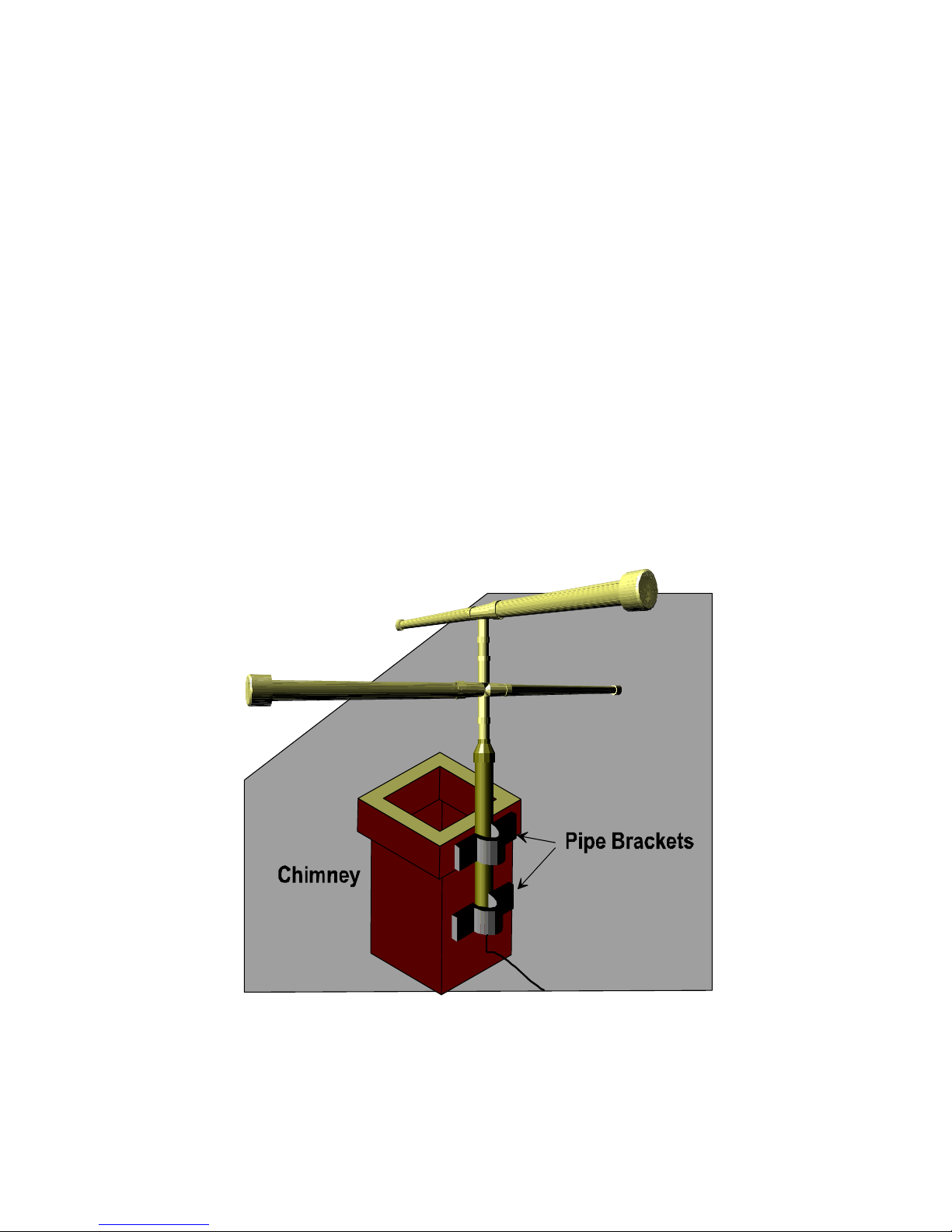
Mounting on a chimney
This is the simplest of methods, as you will need 2, 1 1/2” pipe
brackets (plated metal preferably), 4 self tapping machine screws,
and some plastic anchors.
First line up the antenna with the chimney. If the upper portion of
the chimney is larger than the lower, you may need to mount a
block of wood at the base to make the antenna mast plumb.
Drill the appropriate holes in the chimney for mounting, and then
insert the plastic anchors. Now you can screw the machine screws
into the plastic anchors with the antenna in place.
WSR-ANT • 16
Page 17

Troubleshooting Guide
Problem: When I try to receive a satellite, the reception is really
weak all the way across. Lots of complete dropouts and not
very much in the clear.
Solution: There are many factors involved with this problem, but
the one that concerns this kit is simple. Just twist the top
dipole 180 degrees from its current position. This should
significantly improve reception. If it worsens reception, the
problem may lie elsewhere.
Problem: I don’t receive the satellite, even when it is overhead!
Solution: Again there are many possible problems. Look in your
other manuals for more suggestions. With this kit it is possible
that the elements have been shorted together. You may want
to disassemble the antenna and test this theory out. Also
check your WSR-LNA for proper installation.
Problem: I can’t get it to work no matter what I do!! It must be
Ramsey’s fault!
Solution: Read the warranty information in the back of this
manual.
Other information
If you need more information on antennas such as lightning
protection, or making your own tower or whatever, the ARRL
Handbook is probably the best source for this information. You
can pick one up at any of your favorite HAM stores, or pick one up
at a Hamfest (maybe we will see you there!)
ARRL Handbook. American Radio Relay League, 225 Main St.,
Newington, CT 06111. Annual publications are available.
WSR-ANT • 17
Page 18

The Ramsey Kit Warranty
Please read carefully BEFORE calling or writing in about your kit.
Most problems can be solved without contacting the factory.
Notice that this is not a "fine print" warranty. We want you to understand
your rights and ours too! All Ramsey kits will work if assembled properly.
The very fact that your kit includes this new manual is your assurance
that a team of knowledgeable people have field-tested several "copies"
of this kit straight from the Ramsey Inventory. If you need help, please
read through your manual carefully, all information required to properly
build and test your kit is contained within the pages!
1. DEFECTIVE PARTS: It's always easy to blame a part for a problem in
your kit, Before you conclude that a part may be bad, thoroughly check
your work. Today's semiconductors and passive components have
reached incredibly high reliability levels, and it’s sad to say that our
human construction skills have not! But on rare occasions a sour
component can slip through. All our kit parts carry the Ramsey
Electronics Warranty that they are free from defects for a full ninety (90)
days from the date of purchase. Defective parts will be replaced
promptly at our expense. If you suspect any part to be defective, please
mail it to our factory for testing and replacement. Please send only the
defective part(s), not the entire kit. The part(s) MUST be returned to us
in suitable condition for testing. Please be aware that testing can usually
determine if the part was truly defective or damaged by assembly or
usage. Don't be afraid of telling us that you 'blew-it', we're all human and
in most cases, replacement parts are very reasonably priced.
2. MISSING PARTS: Before assuming a part value is incorrect, check
the parts listing carefully to see if it is a critical value such as a specific
coil or IC, or whether a RANGE of values is suitable (such as "100 to
500 uF"). Often times, common sense will solve a mysterious missing
part problem. If you're missing five 10K ohm resistors and received five
extra 1K resistors, you can pretty much be assured that the '1K ohm'
resistors are actually the 'missing' 10 K parts ("Hum-m-m, I guess the
'red' band really does look orange!") Ramsey Electronics project kits are
packed with pride in the USA. If you believe we packed an incorrect part
or omitted a part clearly indicated in your assembly manual as supplied
with the basic kit by Ramsey, please write or call us with information on
the part you need and proof of kit purchase
WSR-ANT • 18
Page 19

3. FACTORY REPAIR OF ASSEMBLED KITS:
To qualify for Ramsey Electronics factory repair, kits MUST:
1. NOT be assembled with acid core solder or flux.
2. NOT be modified in any manner.
3. BE returned in fully-assembled form, not partially assembled.
4. BE accompanied by the proper repair fee. No repair will be
undertaken until we have received the MINIMUM repair fee (1/2
hour labor) of $18.00, or authorization to charge it to your credit
card account.
5. INCLUDE a description of the problem and legible return address. DO
NOT send a separate letter; include all correspondence with the
unit. Please do not include your own hardware such as nonRamsey cabinets, knobs, cables, external battery packs and the
like. Ramsey Electronics, Inc., reserves the right to refuse repair
on ANY item in which we find excessive problems or damage due
to construction methods. To assist customers in such situations,
Ramsey Electronics, Inc., reserves the right to solve their needs
on a case-by-case basis.
The repair is $18.00 per half hour, regardless of the cost of the kit.
Please understand that our technicians are not volunteers and that setup, testing, diagnosis, repair and repacking and paperwork can take
nearly an hour of paid employee time on even a simple kit. Of course, if
we find that a part was defective in manufacture, there will be no charge
to repair your kit (But please realize that our technicians know the
difference between a defective part and parts burned out or damaged
through improper use or assembly).
4. REFUNDS: You are given ten (10) days to examine our products. If
you are not satisfied, you may return your unassembled kit with all the
parts and instructions and proof of purchase to the factory for a full
refund. The return package should be packed securely. Insurance is
recommended. Please do not cause needless delays, read all
information carefully.
WSR-ANT • 19
Page 20

WSR-ANT Weather Satellite Antenna
Quick Reference Page Guide
Introduction to the WSR-ANT ........... 4
Pipe Diagram .................................... 6
Wiring Diagram ................................. 7
Parts List .......................................... 8
Notes on Assembly .......................... 9
Assembly Steps ................................ 10
Mounting Ideas ................................. 14
Building a Stand ............................... 14
Chimney Mounting ........................... 16
Troubleshooting Guide ..................... 17
Other Information ............................. 17
TOTAL SOLDER POINTS
ESTIMATED ASSEMBLY
Beginner .............. 3.5 hrs
Intermediate ......... 2 hrs
Advanced ............. 1.5 hrs
8
TIME
Price: $5.00
Ramsey Publication No. MWSR-ANT
Assembly and Instruction manual for:
RAMSEY MODEL NO. WSR-ANT WEATHER
SATELLITE RECEIVER ANTENNA KIT
WSR-ANT • 20
Printed on recycled
 Loading...