


4-19.5 MHz
SHORTWAVE RADIO
Ramsey Electronics Model No. SR2
Have you ever wanted to get into the fascinating world of radio? The Ramsey SR2 is a fine performer that will bring in the world using just a few feet of wire as an antenna! Folks of all ages have successfully built and enjoyed this easy and fun kit.
•Enjoy hours of fascinating international listening using just a simple indoor wire antenna
•Select portions of the 4 to 19.5 MHz shortwave band, easily re-tuned at any time
•Smooth varactor diode tuning
•Excellent sensitivity and selectivity
•Front panel Volume and Tuning controls
•Multi-stage audio amplifier for room filling volume
•Well designed superhetrodyne circuit is easy to build, makes a nice one-evening project
•Ideal scout, school, or club project
•Clear, concise step-by-step instructions carefully guide you to a finished kit that not only works - but you’ll also learn too!
•Runs on a standard 9 volt battery
•Add our matching case and knob set for a finished ‘pro’ look

PARTIAL LIST OF AVAILABLE KITS
RAMSEY TRANSMITTER KITS
•FM10A FM Stereo Transmitter
•FM100B Professional Synthesized FM Stereo Broadcaster
•FM25B Synthesized FM Stereo Transmitter
•AM25 Synthesized AM Transmitter
•AM1 AM Transmitter
RAMSEY RECEIVER KITS
• FR1 FM Broadcast Receiver
• AR1 Aircraft Band Receiver
• AA7 Active Antenna
• SC1 Shortwave Converter
RAMSEY HOBBY KITS
•SG7 Personal Speed Radar
•SS70A Speech Scrambler
• TT1 Telephone Recorder
• SP1 Speakerphone
• MD3 Microwave Motion Detector
•PH10 Peak hold Meter
•LC1 Inductance-Capacitance Meter
RAMSEY AMATEUR RADIO KITS
•DDF1 DopplerDirection Finder
•HR Series HF All Mode Receivers
•QRP Series HF CW Transmitters
•CPO3 Code Practice Oscillator
•VLF1 Low Bander Low Frequency SWL Converter
•QRP Power Amplifiers
RAMSEY MINI-KITS
Many other kits are available for hobby, school, scouts and just plain FUN. New kits are always under development. Write or call for our free Ramsey catalog.
4-19.5MHz SHORTWAVE RADIO INSTRUCTION MANUAL
Ramsey Electronics publication No. MSR2 Revision 1.4 First printing: January 2001
COPYRIGHT 2001 by Ramsey Electronics, Inc. 590 Fishers Station Drive, Victor, New York 14564. All rights reserved. No portion of this publication may be copied or duplicated without the written permission of Ramsey Electronics, Inc. Printed in the United States of America.
SR2 – 2

Ramsey Publication No. MSR2
Manual Price Only: $5.00
KIT ASSEMBLY AND INSTRUCTION MANUAL FOR
4-19.5MHz SHORTWAVE RADIO
TABLE OF CONTENTS |
|
Introduction to the SR2 ........................................ |
4 |
What You Can Expect to Hear............................. |
4 |
Shortwave Listening as a Hobby ......................... |
5 |
Circuit Description................................................ |
6 |
Parts Layout Diagram .......................................... |
8 |
Block Diagram ..................................................... |
9 |
Parts List.............................................................. |
10 |
Assembly Instructions.......................................... |
12 |
Schematic Diagram ............................................. |
14 |
Shortwave Antenna Ideas.................................... |
20 |
Initial Testing and Adjustment............................. |
21 |
Troubleshooting Tips ........................................... |
23 |
Ramsey Kit Warranty........................................... |
27 |
SR2 – 3

INTRODUCTION TO THE SR2
The SR2 is a single-conversion superheterodyne receiver designed specifically for listening to AM broadcasting stations in the range of 4 to 19.5 MHz. Because of this "superhet" design, your favorite foreign broadcasting services will come in loud and clear, with pleasing audio sound quality, with a minimum of overload, frequency drift or heterodyne whistles. Because of this broadcast oriented design, other shortwave signals such as Morse code (CW), single-sideband (SSB) voice communications and some Teletype signals will usually sound like garbled hisses. On the other hand, similarly inexpensive receivers designed for CW and SSB can give only marginal performance in receiving broadcast stations due to the lack of superheterodyne design. For example, our popular Ramsey directconversion receivers for the 40,30 and 20 Meter Amateur bands will also pick up AM broadcast stations, but you'll mainly hear their strong AM "carrier" signal due to the lack of the superheterodyne circuitry. Even if such a carrier is tuned to a "null," listening fidelity is less than desirable.
WHAT YOU CAN EXPECT TO HEAR
First, let's take a look at what is POSSIBLE to hear on your SR2. The following are the international shortwave broadcasting bands within its tuning range:
4.750-5.060 MHz. (Lower power, regional "tropical" broadcasting)
5.950-6.200 MHz (Late evening)
7.100-7.300 MHz. (Late afternoon, early evening) (This band is always shared with the 7.0-7.3 MHz Amateur Radio Band)
9.500-19.500 MHz. (Always "something" on, 24 hours a day!)
Especially strong signals include these, among others:
SR2 – 4
•BBC London: an intelligent perspective on world affairs
•Radio Canada International: editorial quality similar to BBC
•Radio Moscow: powerful signals, increasingly honest and open
•Voice of America: VOA broadcasts are "aimed" outside the USA, but if you're in the "path" you'll hear it loud and clear!
•U.S. Armed Forces Radio-TV "Feed" Service: Master programming source for U.S. military radiohear CBS-NBC-ABC-Mutual news all on the same "channel," plus many other features and spots which give a feel for how it's going with those in uniform
•Numerous South American stations
•USA religious broadcasting to other continents
You'll easily tune in broadcasts from many other countries as well. As you become more and more familiar with the world of shortwave broadcasting, you'll be deciding on your own favorite band.
You will hear a variety of other "interesting" sounds, but just remember that this receiver is designed for AM only. If a Morse Code signal really sounds "good," it is because it is being transmitted in AM tone-modulated form, or perhaps the signal is so close to an AM broadcast carrier that the carrier acts as a "beat-frequency-oscillator" (BFO). Even though this receiver can let you tune through several different HAM radio bands, the signals are not likely to be intelligible. Reception of CW and SSB signals on an AM receiver requires a BFO. This is not a complicated feature, but it is beyond the purpose of the SR2. Our companion receivers designed for the HAM bands will let you tune into these SSB and CW broadcasts.
SHORTWAVE LISTENING AS A HOBBY
Many people worldwide enjoy listening to shortwave broadcasts of all kinds, and they keep written records of what they hear. Almost every nation on earth has some sort of shortwave broadcast service, though many are much more challenging to tune than the powerful signals of Radio Moscow and the BBC. In addition, these "SWLs" (Shortwave Listeners) listen to HAM operators, government and commercial stations and even clandestine operations. Some shortwave listeners enjoy collecting QSL cards from stations which they have logged. Shortwave listening is, for some, a step toward getting a HAM radio license. For others, it is a great hobby in itself. The SR2 Shortwave Receiver is a good introductory receiver for this hobby. After you decide exactly what kinds of listening are of the most interest to
SR2 – 5
you, you'll be in a better position to choose a more elaborate receiver. While there are various multi-band portable radios available, you can expect to pay at least $100 for a receiver offering a significant improvement over your trusty SR2.
To learn more about this SWL hobby, look for a copy of "Popular Communications" at newsstands. An inexpensive and interesting general introduction to all kinds of radio listening is the book, "Shortwave Listening Guide" by William Barded, Jr. (1987; Radio Shack Catalog Number 621084). This book also includes helpful introductory information about VHF monitoring, which you can enjoy with the Ramsey FR-146 and AR-1 receiver kits, as well as HAM radio, CB, antennas, and other topics.
To learn more about Ramsey Electronics HAM radio kits, write for our complete catalog. (And, be sure to tell us how you're doing with your SR2 Receiver!) To learn more about the hobby of HAM radio, write ARRL (American Radio Relay League), 225 Main Street, Newington, CT 06111 or visit their website: http://www.arrl.org/.
CIRCUIT DESCRIPTION
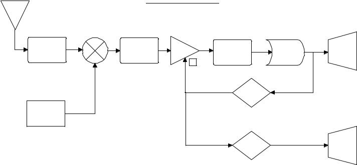
The following paragraphs describe the circuit operation of the SR-2 Shortwave Receiver kit. Through the use of a simplified block diagram the basic circuit theory is easy to understand. The full schematic (pg. 14) shows the details concerning specific operation and component variable configurations.
Take a moment and examine the circuit block diagram found on page 9. The simplified signal flow of the block diagram shows the basic sections of the receiver. The corresponding components are noted under each main block and can be cross referenced to the schematic
The start of our circuit begins with the Antenna. RF Signals (Fc = carrier frequency) from the Antenna are applied to the RF Input and Filtering allowing only the signals of interest to pass through. The high pass filter helps eliminate unwanted signals picked up by the antenna improving the overall reception quality of the radio.
After the input signal is filtered, it moves to the Mixer stage. Notice on the diagram that there are two inputs to the mixer. We have discussed one of these input signals coming into the mixer but not the other as of yet. Drop down to the Local Oscillator block. The local oscillator (LO for short) acts as your tuning control for what frequencies you can receive by generating a signal on the board close in value to that which will be used by the mixer. There is a direct relationship between the generated frequency of the local oscillator (LO) and the exact receive frequency (Fc) you want to listen to. This will become clear when we finish discussing the block diagram.
The LO section is a Colpitts oscillator that takes advantage of smooth
SR2 – 6
varactor diode tuning. The varactor (D3) forms an L/C (Inductor/Capacitor) tank circuit with T3. Increasing the voltage on the varactor diode with R21 (Tuning Pot) increases the capacitance of D3 thus increasing the frequency output of the LO section.
Now that we know the two signals coming into the Mixer stage, both the Fc (receive carrier frequency) and the LO (generated local oscillator), we can better cover its operation. The mixer takes these input signals and performs a few very basic operations. The technical explanation of how the mixer combines these signals through Fourier Series is interesting but very drawn out. The point of using the block diagram, however, is to simplify matters. Therefore, the function of the mixer is to obtain the ‘product’ and the ‘sum’ of the input signals. This means you take the input signals and merely ‘add’ and ‘subtract’ their values to determine what you get on the output. The general formulas to use are quite simply, ‘Fc + LO = Mixer Output’ and ‘Fc – LO = Mixer Output’.
The realistic output of the mixer stage unfortunately has other signals besides the ones we want. This brings us to the next stage, Intermediate Frequency Filtering. An Intermediate Frequency (IF) is a signal somewhere between the RF signal Fc we started with and the final audio message we are trying to get. The desired IF we are dealing with is a fixed number, such as 455 kHz. As long as the proper relationship between Fc and the LO exists, the IF value will stay constant. Due to the fact that the IF frequency stays the same all the time, the Intermediate Frequency Filter can be very narrow. The filter will remove any other signals coming from the mixer that are not in the proper pass band and yield a clean signal for further processing.
The next stage is an Amplifier with an adjustable gain feedback loop. The gain control is dependant on the amount of signal being received (this Automatic Gain Control ‘AGC’ will be covered in a moment). The amplifier boosts the signal level of the incoming IF and gives us a stronger signal to work with.
After the amplifier stage is another Intermediate Frequency Filter. This helps remove any unwanted residual signals still present and cleans up the amplified IF for a high quality signal.
At this point the audio signal we are trying to obtain is riding on the IF signal. The Demodulator circuit finally extracts the message from the IF through a process called envelope detection. Now that we have our message back in the audio realm, it is directed through the audio circuitry to the speaker output.
Wait, there are still a few sections we have not discussed!
The demodulated audio branches off before the audio circuitry and is used to perform some useful functions. The RSSI LED, Received Signal Strength Indicator Light Emitting Diode, gives us a general signal level feature. The stronger the signal we receive, the brighter the LED will glow. This is great for help pulling in those weak transglobal transmitter signals. The gain of the
SR2 – 7

RSSI circuit is controlled by the value the feedback resistor R17. If you are commonly using a small antenna and listening to weak signals, increase the value of R17 to customize the response indication of D2, the signal strength LED.
The final stage, and the real secret to the sensitivity of the receiver, is the Automatic Gain Control (AGC). The gain control looks at the amount of signal level present at the output of the demodulator and varies the amount of gain the Amplifier has accordingly. If there is a strong signal coming through the demodulator the AGC circuit lowers the gain of the amplifier. If the receive signal coming through the demodulator is very weak, the AGC circuit increases the gain of the amplifier (Q2) allowing us to receive signals from around the world and listen to them with clarity.
SR2 PARTS LAYOUT DIAGRAM
SR2 – 8
9 – SR2
An tenna |
|
SR -2 Block D iagram |
|
||
|
|
|
|
|
|
J1 |
|
|
|
|
|
|
M ixer |
|
|
|
|
RF Input |
|
Interm ediate |
|
Interm ediate |
|
& |
|
Frequency |
Am p |
|
|
|
Frequency |
Dem od |
|||
Filtering |
|
Filter |
|
||
|
Q2 |
Filter |
|
||
|
|
|
|
||
C1,C2,C3 |
Q1 |
T1 |
|
|
|
|
T2 |
D1 |
|||
L1,L2 |
|
|
|
||
|
|
|
|
|
|
|
|
|
|
AG C |
|
Local |
|
|
|
Autom atic Gain Control |
|
Oscillator |
|
|
|
U 1:A |
|
|
|
|
|
|
|
T3,D 3,Q 3 |
|
|
|
|
|
C15,C16 |
|
|
|
RSSI |
|
R21 |
|
|
|
|
|
|
|
|
|
|
|
|
|
|
|
Receive Signal |
|
|
|
|
|
Strength Indicator |
|
|
|
|
|
U 1:B |
|
Audio (Speaker)
U 2, J2
Signal
Strength
LED
D2
 Loading...