

Page 1

Ramsey Electronics Model No. SCA1
• Tunes entire SCA subcarrier band 50 - 100 KHz
• Excellent performance - uses PLL decoder
• Feature both speaker and line-level audio outputs
• Connects to any FM receiver or simply plugs into our
FR-1 FM broadcast receiver
• Band-pass filtered input for excellent fidelity
• Front panel volume and tuning controls
• Informative manual answers questions on
theory, hook-ups, and uses - enhances resale
value , too!
• Add our case set for a finished ‘Pro’
look. Cases match all Ramsey products
• Clear, concise assembly instructions carefully guide you
to a finished kit that works the FIRST time!
SCA FM SUBCARRIER
DECODER KIT
Commercial-free music, stock quotes, news - all available
around-the-clock on your local FM station? Sure, buried in a
special subcarrier that you’ll be able to tune with the SCA-1.
This is how most restaurants, department stores, and hotels
pick up their music.
Page 2

SCA1 • 2
RAMSEY TRANSMITTER KITS
• FM100B Professional FM Stereo Transmitter
• FM25B Synthesized Stereo Transmitter
• AM1, AM25 AM Transmitters
• TV6 Television Transmitter
RAMSEY RECEIVER KITS
• FR1 FM Broadcast Receiver
• AR1 Aircraft Band Receiver
• SR2 Shortwave Receiver
• AA7 Active Antenna
• SC1 Shortwave Converter
RAMSEY HOBBY KITS
• SG7 Personal Speed Radar
• SS70A Speech Scrambler
• SP1 Speakerphone
• WCT20 Wizard Cable Tracer
• PH10 Peak hold Meter
• LC1 Inductance-Capacitance Meter
RAMSEY AMATEUR RADIO KITS
• DDF1 Doppler Direction Finder
• HR Series HF All Mode Receivers
• QRP Series HF CW Transmitters
• CW7 CW Keyer
• CPO3 Code Practice Oscillator
• QRP Power Amplifiers
RAMSEY MINI-KITS
Many other kits are available for hobby, school, Scouts and just plain FUN. New
kits are always under development. Write or call for our free Ramsey catalog.
SCA1 FM AUDIO SUBCARRIER DEMODULATOR KIT INSTRUCTION MANUAL
Ramsey Electronics publication No. MSCA1 Revision 1.2a
COPYRIGHT
1994 by Ramsey Electronics, Inc. 590 Fishers Station Drive, Victor, New York
14564. All rights reserved. No portion of this publication may be copied or duplicated without the
written permission of Ramsey Electronics, Inc. Printed in the United States of America.
Page 3

SCA1 • 3
Ramsey Publication No. MSCA1
Price $5.00
TABLE OF CONTENTS
Introduction to the SCA .................. 4
FM and subcarrier background ...... 4
Circuit description .......................... 6
Parts list ......................................... 7
Parts layout diagram ...................... 9
Schematic diagram ...................... 10
Assembly instructions .................. 11
Set-up and testing ........................ 15
Hook-up details ............................ 16
Troubleshooting guide ................. 17
Enclosure ideas ........................... 18
Ramsey kit warranty .................... 19
KIT ASSEMBLY
AND INSTRUCTION MANUAL FOR
SCA1 FM AUDIO
SUBCARRIER
DEMODULATOR
Page 4

SCA1 • 4
INTRODUCTION
The Ramsey Subcarrier Adapter kit allows you to hear the commercial free
background music that is broadcast along with some commercial FM signals.
This is accomplished by connecting the SCA1 to a standard FM broadcast
receiver tuned to the local FM station which is providing the subcarrier
service. The SCA1 then acts as a second receiver tuning in subcarrier
signals that are modulated along with the regular FM broadcast
programming. Be aware that not all cities have FM stations that transmit
SCA subcarrier signals, but if any are there, the SCA1 will find them!
While this kit can be easily assembled using our step by step instructions,
the actual connection to a FM receiver can be quite complicated and should
only be attempted by a qualified technician. This interconnection will be
described later in more detail. If you decide not to delve into your existing FM
receiver, we offer an FM broadcast band receiver with SCA baseband
demodulator output (model FR-1) which allows an easy, one step hookup for
the adapter.
Due to the myriad of different receivers and possible combinations that can
be encountered, Ramsey regrets that it cannot assume any responsibility for
connection to your FM receiver, or to provide any more specific information
than that which is provided in this manual.
BUILDING YOUR SCA1 KIT
There are over 100 solder connections on the SCA1 printed circuit board.
That means your work could be 99% perfect and you could still have 1 or 2
poor solder joints or solder bridges. Please take us seriously when we say
that good soldering technique is essential to the proper operation of your
subcarrier demodulator. Here are a few tips for a trouble-free assembly:
• Use a 25-50 watt soldering pencil with a clean tip.
• Use only rosin core solder intended for electronic use.
• Use bright lighting. A magnifying lamp or bench-style magnifier
may be helpful.
• Do your work in stages, taking breaks to check your work.
• Carefully brush away wire cuttings so they don't lodge between
solder connections.
Page 5

SCA1 • 5
FM BROADCASTING AND SUBCARRIERS - SOME BACKGROUND
Before we explain how the SCA decoder works, we first need to know what it is
"looking" for in the received FM signal. (A note to newcomers: don't let this
description scare you. Rest assured that your SCA decoder will perform the
desired task even if you don't fully grasp all the theory that is thrown at you
in the following passages).
Let's discuss what's happening in the Frequency Modulated signal coming from
a commercial transmitter. Look at the diagram above (referred to in
engineering circles as a spectral diagram) to help you understand what we're
about to describe. The signal contains a Left+Right FM modulated carrier which is the standard monaural audio signal - and a Left-Right signal which is
used to provide the stereo signal. Follow closely to see how we get separate
Left and Right stereo audio channels, and its not done with mirrors - only
simple algebra!
First, let's see what we have to deal with:
1. A Left+Right signal (called the mono audio channel)
2. A Left-Right signal (called the difference audio channel).
Now let's apply a little algebraic addition:
(L+R) + (L-R) = L+L+R-R = 2L (the R terms cancel)
The Left audio channel.
Now, how about a little algebraic subtraction:
(L+R) - (L-R) = L-L+R-(-R) = 2R (the L terms cancel)
The Right audio channel.
Now, the number "2" in 2R and 2L simply means that the signal is twice the
amplitude (twice as loud) and should not be confused with interpreting it as two
left or right channels.
Page 6

SCA1 • 6
Well, you may say, that works out nicely, but why not just transmit a separate
Left and separate Right channel, and avoid the math? There are a couple of
reasons why: One, to receive on a Mono receiver, the receiver would have to
detect and demodulate both Left and Right signals and combine them for the
L+R mono channel. The extra cost of adding another demodulator would
unnecessarily raise the cost of simple mono receivers. And, two: signal
bandwidth is limited; there is not enough "room" for an independent (Left Right) carrier. In fact, to conserve bandwidth even more, the stereo subcarrier
is transmitted in Double-Side-Band-Suppressed-Carrier (DSBSC) mode. This
signal is located 38 KHz away from the center frequency that the receiver is
tuned to. To recover this audio, a 19 KHz subcarrier (called the "pilot") is
transmitted. In the receiver, this pilot signal is doubled to 38 KHz and is used to
properly demodulate the Left - Right signal.
Have you ever noticed that no matter how expensive the FM receiver is, the top
end of the frequency response is always less than 19 KHz? If it wasn't, while
sitting back enjoying your Hi-Fi, you'd be able to smell your tweeters burning up
as they tried to reproduce the constant 19KHz pilot signal! In addition to all this
activity, there may be another subcarrier, usually 67 KHz away from the center
frequency, containing completely independent audio! Normally your receiver
would effectively filter out this signal, but this is the subcarrier that we are
interested in, and is what our kit is designed to tune in and demodulate.
Why all this talk about stereo and its subcarriers? To give you a little familiarity
with subcarriers and to let you know that there's more out there than expected!
SCA1 CIRCUIT DESCRIPTION
The input is bandpass filtered using L1, L2, and associated components to
isolate the higher frequency subcarriers. The filtered signal is then amplified by
Q1 and applied to the PLL (Phase-Locked-Loop) detector IC chip. The LM565
Phase Lock Loop IC "tracks" the difference between the input signal and its
own internal reference oscillator. This tracking voltage is the recovered audio,
and is low passed by R8-10 and C12-14. A low level audio output is supplied
for an external audio amplifier, or a speaker may be used directly via the
amplified audio output at J3.
Page 7

SCA1 • 7
SCA1 SUBCARRIER DEMODULATOR KIT PARTS LIST
RESISTORS
1 2 ohm [red-black-gold] R13
4 1K ohm [brown-black-red] R8,9,10,11
1 2.2K ohm [red-red-red] R3
4 10K ohm [brown-black-orange] R2,5,6,7
1 22K ohm [red-red-orange] R14
1 220K ohm [red-red-yellow] R4
CAPACITORS
3 .001 uf disc [marked .001 or 102 or 1nf] C3,7,9,10,11
5 .01 disc [marked .01 or 103 or 10nf] C1,6,8,14,20
3 .1 uf disc [marked .1 or 104] C12,13,19
1 100 pf disc [marked 100 or 101] C5
1 2200 pf disc [marked 222, 2200 or 2.2 nf] C4
5 10 uf electrolytic C2,15,16,21,22
2 220 uf electrolytic C17,18
INDUCTORS
2 1800 uH [large green cylinder marked 182]
SEMICONDUCTORS AND IC'S
1 LM565 14 pin DIP
1 LM386 8 pin DIP
2 2N3904 NPN transistors
OTHER COMPONENTS
1 SCA1 Printed circuit board
1 DPDT push-button switch S1
2 10K ohm PC mount potentiometer R1,12
2 PC mount RCA jack J1,2
1 PC mount subminiature speaker jack J3
1 9-volt battery bracket
1 9-volt battery snap-on clip
REQUIRED, NOT SUPPLIED
1 9-volt alkaline battery
1 Speaker or headphones
1 Ramsey CSCA case and knob set
NOTE CONCERNING THE AUDIO OUTPUT JACK
Your receiver kit is supplied with a standard subminiature 2.5 mm (3/32") audio
output jack, which mates with commonly available earphone plugs and adapters
available at Radio Shack, such as 274-290 (plug) or 274-327 (adapter for 1/8"
mono plug). If you prefer to use another size and style jack, we suggest that you
still install the original jack and then wire your own jack in parallel with it rather to
rough up the PC board to accommodate your jack.
Page 8
SCA1 • 8
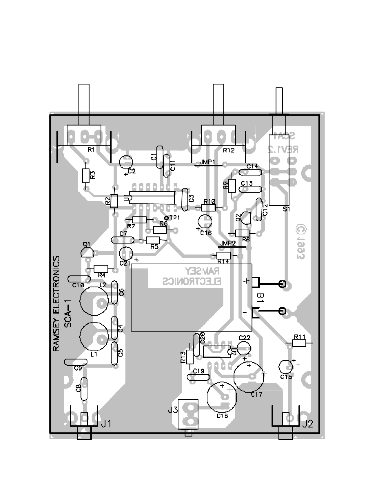
SCA SUBCARRIER DEMODULATOR PARTS LAYOUT DIAGRAM
Page 9

SCA1 • 9
Page 10

SCA1 • 10
RAMSEY Learn-As-You-Build KIT ASSEMBLY:
We have a two-fold "strategy" for the order of the following kit assembly
steps. First, we install parts in physical relationship to each other, so there’s
a minimal chance of inserting wires into wrong holes. Second, whenever
possible, we install in an order that fits our “Learn-As-You_Build” kit building
philosophy.
For each part, our word “Install” means:
1 Pick the correct part value to start with.
2 Insert it into the correct PC board location.
3 Orient it correctly, which means: Follow the PC board drawing and the
written directions for all parts where there's a right way and a
wrong way to solder it in. (Note diode bands, electrolytic capacitor
polarity, transistor shapes, dotted or notched ends of IC's, and so
forth.)
4 Push the component as close to the component side as is
mechanically possible; this will keep the component side neat and
prevent parts from "radiating" signals to undesired locations.
5 Solder all connections unless directed otherwise. Use enough heat
and solder flow for clean, shiny, completed connections. Don't be
afraid of any pen-style soldering iron having enough heat to damage
a component.
6 Trim or "nip" excess wire lengths after soldering.
NOTE: Save some of the longer wire scraps nipped from resistors and
capacitors. These will be used to form wire jumpers (JMP1, etc.) to be
soldered in just like parts during these construction steps.
FIRST ASSEMBLY STEPS
Since you may appreciate some warming-up soldering practice as well as a
chance to put some "landmarks" on the SCA1 PC board, we first will install
some "hardware" components, to make the up-down, left-right orientation of
the PC board as clear as possible. Initially, it can be quite confusing to find
the right holes, even for an experienced builder. Just remember that the
"component" side of the circuit board, the side shown in the parts layout
diagram, is viewed from the top side. There are no PC traces on this side of
the circuit board, the component leads will pass through the board and be
soldered on the "solder" side of the board.
Page 11

SCA1 • 11
Now let's start building
1. Press S1 firmly into its six holes and solder all six pins. The switch fits
the board only one way.
2. Install J1 and J2, the RCA-style audio jacks. Solder all 4 points. You'll
notice that the mechanical grounding tabs will take longer to solder.
This is due to the fact that the large metal tab of the component as well
as the "ground plane" of the circuit board must be sufficiently heated to
allow the solder to flow completely. Don't be afraid to leave the
soldering iron on the connection long enough to make a good
connection.
3. Install J3, the subminiature phone jack. Solder all three points. Be
gentle and patient in inserting, taking care not to damage the solder
tabs.
4. Install controls R1 and R12. Insert the PC mounted control firmly into
its position. Check that the control is pressed in firmly and straight
against the top of the board. Solder the three center pins and then the
two larger mechanical mounting tabs. Use enough solder for a solid,
robust connection.
Also, if you plan to use an enclosure other than the custom Ramsey enclosure
and knob kit, you may wish to locate the controls differently than provided by
the PC board. In this case, the control lugs are wired to the PC board using
your own insulated hookup wire as short as possible for a neat installation.
SUBCARRIER INPUT AND BANDPASS FILTER
5. Install C8, .01 uf disc [marked .01 or 103 or 10nf]. It is located just
above jack J1.
6. Install C9, .001uf disc [marked .001, 102 or 1 nf].
7. Install C5, 100 pf disc [marked 100 or 101].
8. Install C4, 2200 pf disc [marked 2200, 222 or 2.2 nf].
9. Install C6, .01uf disc [marked .01, 103 or 10 nf].
10. Install C10, .001uf disc [marked .001, 102 or 1 nf].
11. Install L1, 1800uH inductor [a large green cylinder labeled 182].
12. Install L2, the other 1800uH inductor [again, marked 182].
Page 12

SCA1 • 12
13. Install R4, 220K ohm [red-red-yellow].
14. Install Q1, the 2N3904 transistor. The PC board drawing shows how the
flat side of each transistor points in relation to other parts. To install a
transistor, press its three leads in place as far as they go without forcing. The
wires may be spread as needed to hold it in place before soldering. Don’t
hesitate to use sufficient soldering heat to make good connections.
15. Install R2,10K ohm [brown-black-orange]. Be sure to save some of the
component leads that you clip. You’ll need them later to make jumper wires.
16. Install C7, .001 disc [marked .001 or 102].
Take some time now to re-check your solder connections. Be certain that there
are no solder bridges between components or foil runs. Make sure all component
leads are trimmed. Re-solder any connection which is less than perfect.
BUILDING THE VOLTAGE CONTROLLED OSCILLATOR
17. Install R3, 2.2K ohm [red-red-red].
18. Install C2, 10uf electrolytic capacitor. Electrolytic capacitors are polarized
and must be installed correctly. They are usually marked with a black stripe
and a (-) indicating their negative lead. PC boards will usually indicate the (+)
hole.
19. Install C21, another 10uf electrolytic capacitor. Observe correct polarity.
20. Install R5, 10K ohm [brown-black-orange].
21. Install R6, 10K ohm [brown- black-orange].
22. Install R7, 10K ohm [brown-black-orange].
23. Install U1, the LM565 PLL IC. Use care when inserting the IC into the
circuit board not to bend one of the pins so it doesn’t pass through the circuit
board. Note also that one end of the of the IC is marked by a dot, notch, or
band; this end must be oriented as shown on the PC board layout diagram.
24. Using a scrap lead, install a test point in the TP1 position. Usually, it is
best to bend the wire in a loop at the top so it is easy to connect to when a
test is required.
Page 13

SCA1 • 13
25. Install C1, .01uf disc [marked .01 or 103 or 10nf].
26. Install C11, .001uf disc [marked .001 or 102].
27. Install C3, .001uf [marked .001 or 102].
28. Using a scrap resistor lead, form a jumper wire to insert in the PC
board in the JMP1 position. Jumpers act as electronic bridges carrying
signals over PC board traces underneath.
29. Install R14, 22K ohm [red-red-orange].
The VCO/PLL section of the SCA1 is now complete. The VCO’s internal
oscillator frequency can be adjusted using pot R1. The PLL section will then
compare the applied input frequency with the VCO frequency. If they are within
“locking range” the PLL section will adjust the VCO control voltage to make it
lock to exactly the same frequency as the input. If the input frequency changes
(as when it is frequency modulated), the VCO will track and follow it exactly. In
this way, the control voltage provides an exact replica of the modulation on the
input signal.
AUDIO FILTERING AND AMPLIFICATION
30. Install R10, 1K ohm [brown-black-red].
31. Install C16, 10uf electrolytic capacitor (observe correct polarity).
32. Install R9, 1K ohm [brown-black-red].
33. Install C14, .01 disc [marked .01 or 103 or 10nf].
34. Install C13, .1 uf disc [marked .1 or 104].
35. Install C12, .1 disc [marked .1 or 104].
36. Install R8, 1K ohm [brown-black-red].
37. Install Q2, the 2N3904 transistor. Observe correct placement of the flat
side.
38. Install jumper, JMP2. Use a scrap resistor or component lead..
39. Install R11, 1K ohm [brown-black-red].
40. Install C15, 10 uf electrolytic. Make certain that the polarity is correct.
41. Install C17, 220 uf electrolytic. Check that polarity!
Page 14

SCA1 • 14
42. Install C18, 220 uf electrolytic. Again, check that polarity!
43. Install C19, .1 uf disc [marked .1 or 104].
44 Install C20, .01 uf disc [marked .01 or 103 or 10nf].
45. Next we'll install U2, the LM 386 audio amplifier IC. Use care when
inserting the IC into the circuit board not to bend one of the pins so it does
not pass through the circuit board. Note also that one end of the IC is
marked by a dot, notch or band; this end must be oriented as shown on the
PC board layout diagram.
46. Install R13, 2 ohm [red-black-gold].
47. Install the battery snap terminal leads, making sure that the positive
(red) lead is inserted into the (+) hole on the PC board and the negative
(black) into the (-) hole.
48. The battery bracket may be attached in a variety of ways. A wire
jumper can be passed through the two holes on the PC board, then both
ends soldered on the underside of the board.
49. A note concerning capacitor C22. If this component is installed, the
audio gain will be significantly increased. This can, however, be too much of
a good thing and cause feedback or audio distortion depending on the
speaker used. It's recommended that you do not install the component
initially, but add it after your SCA decoder has been tested and verified that
all else is working correctly. When and if you choose to install C22, a 10 uf
electrolytic, be sure to observe the polarity. Follow the parts layout diagram
for component orientation.
CONGRATULATIONS
Your subcarrier decoder is completed! Take a minute to step back and have a
look at your work. If you have the patience, we suggest a short break. Then,
take a magnifying lens and a bright light and examine all your solder joints,
touching up any connection which appears less than perfect. Make sure all
excess leads have been trimmed, and that there's not one bent back flat against
the board, probably causing a short. Brush the solder side of the board with a
stiff brush to make sure that no loose wire trimmings or solder drippings (tsk
tsk) are lodged between connections.
SCA DECODER SETUP AND TESTING
Initially, the demodulator can be tested as follows :
Page 15
SCA1 • 15
1. Install a fresh 9 VDC battery; an alkaline is preferred.
2. Push the power switch to the "on" position. The unit should draw about
20 ma from the 9 VDC source, without a speaker connected.
3. Using a frequency counter or oscilloscope connected to TP1, verify that
there is a square wave present. This square wave should be approximately
6v p-p. As you turn the "tuning" pot, R1, the oscillator frequency should
vary from about 50 kHz to 110 kHz. Don't be concerned if the range is not
exactly 50 to 110 KHz, just as long as 60 to 80 KHz is covered.
4. If you have access to an audio oscillator, you may apply a signal in the
50 to 100 KHz range to the input of the SCA1. While watching the TP1 test
point, you should see the frequency changing to match the applied signal.
5. Connect a small speaker to the SCA1's audio output jack, J3. With no
signal applied, you should hear a hiss similar to the interstation noise
heard on a standard FM radio. As the audio oscillator is tuned to the
frequency that the SCA1 is tuned to, you should hear a quieting in the
speaker.
These check verify almost completely the proper operation of the SCA1. We're
now ready to actually hook-up the SCA1 to an FM receiver.
HOOK-UP TO AN FM RECEIVER
Hooking up your SCA1 to an FM receiver can be easy or difficult and
frustrating. The Ramsey FR-1 FM broadcast band receiver has a convenient
baseband output for easy connection to the SCA1; other commercial FM radios
aren't quite as easy.
Hooking up the SCA1 to an FM receiver involves locating the baseband
demodulator output on the FM receiver. Some older tube-style FM radios have
what is known as a "multiplex" output jack. This jack was for connection of an
external stereo adapter. The multiplex output was nothing more than a buffered
output right from the receiver's FM detector. This output was not low-pass
filtered in any way and contained all the modulation information that was
Page 16

SCA1 • 16
contained on the received signal. If you have a receiver with such an output
jack, you're in luck; simply hook-up the SCA-1 to that jack.
If your radio does not have a multiplex output jack but you are fortunate enough
to have the schematic of your receiver, then look for the point where the stereo
demodulator is connected to the FM detector. That point will be the baseband
demodulated output.
However, for most of us, we'll have to poke around within our receiver to locate
the proper point in which to find the baseband demodulated signal. Probably the
easiest way is to power up your subcarrier decoder with a speaker attached and
search around within the receiver for the point that allows operation (yes, that's
trial and error, but without a circuit diagram for the receiver under question, it's
pretty much the only way!). A few educated guesses will help us to at least look
in the right places. The demodulator is the last point in the receiver chain where
RF/IF frequencies and their attendant IF transformers are found. So, we can be
pretty certain that the IC chip following the last IF transformer is the detector.
Use a length of coax cable with the center conductor stripped back as a
convenient probe to allow touching various points within your receiver. The coax
shield, of course, is attached to the receiver's ground. The other end of this coax
is connected to the SCA1's input jack, J1. (If your radio is plugged into the AC
line, be sure to use caution when poking around! And, be sure your SCA1,
speaker and other wires are not touching you or your workbench - no need to
risk getting a nasty shock!) With the receiver tuned to a local FM station known
to be transmitting an SCA signal, the coax is probed around various circuit
points until a signal is heard. Leave the SCA1 tuned to 67 KHz (about midpoint
on R1) since most SCA signals are at 67 KHz.
We're sorry we can't be more specific on how to connect to an FM receiver, but
there are many different types of radios on the market and we can't explain them
all! Also, please don't call us and ask us to tell you where to connect up in your
"Blitz-Tone Model K743" FM radio. We simply do not have the man-power to
trace out each schematic for each and every one of our most anxious builders!
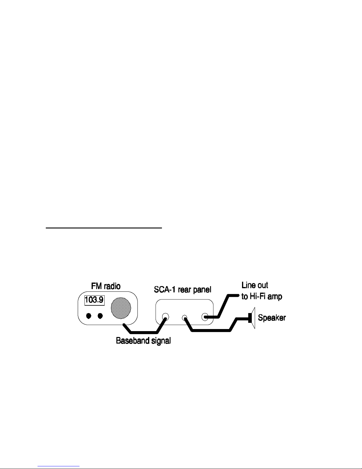
The speaker output at J3 will provide plenty of volume to a small speaker, but if
you wish to connect to your big Hi-Fi system, use output jack J2. This output is
suited to connect to your line-level input on your audio amplifier or stereo
system. Just remember that it is mono.
*A note concerning commercial use
*
Although you may listen to these SCA broadcasts in you own home, any
commercial usage, such as restaurant, bar, store or even at parties is
considered theft of service and the owner of the copyrighted SCA service
is entitled to collect payment. So, be cool, OK?
Page 17

SCA1 • 17
TROUBLESHOOTING GUIDE
If your SCA1 doesn't work, a thorough check of the component placement will
usually turn up the problem. Checking your work backwards through the
assembly steps is very effective in locating placement errors. If the unit appears
to operate correctly, but just doesn't seem to pick up any SCA programs,
maybe there are no FM stations in your area that are transmitting SCA signals.
Sometimes a phone call to a radio station Chief Engineer will steer you in the
right direction, but be sure to let him know you are a hobbyist and not out to
steal the SCA programming!
Lastly, interconnection to your FM receiver is probably the area where most
problems can develop, and it's also the area where we can offer the least
amount of help. In this case we can only suggest that you verify that the SCA1
does indeed operate using an audio generator as outlined in the Testing
section of your manual. The use of your SCA1 with the Ramsey FR-1 FM
broadcast receiver is the only combination that we here at the factory have any
familiarity with. Here are a few common problems along with solutions which
may help in simple troubleshooting:
• PROBLEM: Occasionally good but erratic operation.
• SOLUTION: Check very carefully for poor solder connections.
• PROBLEM: Loud AC hum or buzz.
• SOLUTION: . If you are using a 9-volt AC power adapter, the adapter
design may not be of sufficient quality for this application. Try bypass
capacitors, a different adapter, or a well designed and filtered DC power
supply.
• PROBLEM: Signals have unpleasant distortion or tune in "funny".
• SOLUTION: Signal level into the SCA1 is too high. Reduce the level by
adding a resistor in series with the cable to J1 (try values from 1K to 22K).
• PROBLEM: VCO oscillator measured at TP 1 is inoperative or wrong
frequency.
• SOLUTION: In addition to checking solder joints, be sure that R3 and C11
are the correct values. These are the frequency determining components.
• PROBLEM: Unit receives when R1 is adjusted, but drifts away or is very
noisy.
• SOLUTION: Signal level into the SCA1 is too low. Try a different point
within your FM receiver for connection of the SCA1.
Page 18

SCA1 • 18
• PROBLEM: Audio is good from the Low Level output jack, J2, but no
speaker audio.
• SOLUTION: Check all circuitry around U2, the audio amplifier section.
• PROBLEM: Unit has low frequency "growl," squeal or erratic operation
when volume is turned up.
• SOLUTION: It’s nothing more than a dead battery. When the audio
amplifier draws peaks of current on loud sounds, its voltage temporarily
falls, causing the PLL circuit to drop lock.
A careful check of all construction will solve your problem. Over 95% of the
kits returned for repair have nothing more than a simple assembly or
construction error! Have another pair of eyes check your work first.
ENCLOSURE IDEAS
While we believe that the Ramsey enclosure and knob option is a fine value
for finishing off your Ramsey receiver or transmitter, we are happy to give you
an alternate suggestion. If your first goal is economy and rugged portability,
you will find that the circuit board can be mounted nicely in a standard VHS
videotape storage box, which also gives room for a speaker, or earphone
storage, and even a set of connection cables. The controls are easily mounted
at one end of such a box. It may be necessary to cut away the molded posts
which secure the tape cassette itself. These storage boxes come in several
styles, so pick one that looks truly practical as a project enclosure.
Page 19

SCA1 • 19
The Ramsey Kit Warranty
Please read carefully BEFORE calling or writing in about your kit. Most problems can be solved
without contacting the factory.
Notice that this is not a "fine print" warranty. We want you to understand your rights and ours too! All
Ramsey kits will work if assembled properly. The very fact that your kit includes this new manual is
your assurance that a team of knowledgeable people have field-tested several "copies" of this kit
straight from the Ramsey Inventory. If you need help, please read through your manual carefully, all
information required to properly build and test your kit is contained within the pages!
1. DEFECTIVE PARTS: It's always easy to blame a part for a problem in your kit, Before you conclude
that a part may be bad, thoroughly check your work. Today's semiconductors and passive components
have reached incred bly high reliability levels, and it’s sad to say that our human construction skills
have not! But on rare occasions a sour component can slip through. All our kit parts carry the Ramsey
Electronics Warranty that they are free from defects for a full ninety (90) days from the date of
purchase. Defective parts will be replaced promptly at our expense. If you suspect any part to be
defective, please mail it to our factory for testing and replacement. Please send only the defective part
(s), not the entire kit. The part(s) MUST be returned to us in suitable condition for testing. Please be
aware that testing can usually determine if the part was truly defective or damaged by assembly or
usage. Don't be afraid of telling us that you 'blew-it', we're all human and in most cases, replacement
parts are very reasonably priced.
2. MISSING PARTS: Before assuming a part value is incorrect, check the parts listing carefully to see
if it is a critical value such as a specific coil or IC, or whether a RANGE of values is suitable (such as
"100 to 500 uF"). Often times, common sense will solve a mysterious missing part problem. If you're
missing five 10K ohm resistors and received five extra 1K resistors, you can pretty much be assured
that the '1K ohm' resistors are actually the 'missing' 10 K parts ("Hum-m-m, I guess the 'red' band
really does look orange!") Ramsey Electronics project kits are packed with pride in the USA. If you
believe we packed an incorrect part or omitted a part clearly indicated in your assembly manual as
supplied with the basic kit by Ramsey, please write or call us with information on the part you need
and proof of kit purchase
3. FACTORY REPAIR OF ASSEMBLED KITS:
To qualify for Ramsey Electronics factory repair, kits MUST:
1. NOT be assembled with acid core solder or flux.
2. NOT be modified in any manner.
3. BE returned in fully-assembled form, not partially assembled.
4. BE accompanied by the proper repair fee. No repair will be undertaken until we have received the
MINIMUM repair fee (1/2 hour labor) of $25.00, or authorization to charge it to your credit card
account.
5. INCLUDE a description of the problem and legible return address. DO NOT send a separate letter;
include all correspondence with the unit. Please do not include your own hardware such as
non-Ramsey cabinets, knobs, cables, external battery packs and the like. Ramsey
Electronics, Inc., reserves the right to refuse repair on ANY item in which we find excessive
problems or damage due to construction methods. To assist customers in such situations,
Ramsey Electronics, Inc., reserves the right to solve their needs on a case-by-case basis.
The repair is $50.00 per hour, regardless of the cost of the kit. Please understand that our technicians
are not volunteers and that set-up, testing, diagnosis, repair and repacking and paperwork can take
nearly an hour of paid employee time on even a simple kit. Of course, if we find that a part was
defective in manufacture, there will be no charge to repair your kit (But please realize that our
technicians know the difference between a defective part and parts burned out or damaged through
improper use or assembly).
4. REFUNDS: You are given ten (10) days to examine our products. If you are not satisfied, you may
return your unassembled kit with all the parts and instructions and proof of purchase to the factory for
a full refund. The return package should be packed securely. Insurance is recommended. Please do
not cause needless delays, read all information carefully.
Page 20

SCA1 • 20
SCA1 FM SUBCARRIER DECODER KIT
Quick Reference Page Guide
FM and subcarrier background .......4
Circuit description ...........................6
Parts list ..........................................7
Parts layout diagram .......................9
Schematic diagram .......................10
Assembly instructions ...................11
Set-up and testing .........................15
Hook-up details .............................16
Troubleshooting guide ..................17
Enclosure ideas ............................18
Ramsey kit warranty .....................19
Price: $5.00
Ramsey Publication No. MSCA1
Assembly and Instruction manual for:
RAMSEY MODEL NO. SCA1 SCA DECODER KIT
This Quality
Electronics Kit was
designed and
packed in the USA
REQUIRED TOOLS
• Soldering Iron Ramsey WLC100
• Thin Rosin Core Solder Ramsey RTS12
• Needle Nose Pliers Ramsey MPP4 or
RTS05
• Small Diagonal Cutters Ramsey RTS04
<OR> Technician’s Tool Kit TK405
ADDITIONAL SUGGESTED ITEMS
• Holder for PC Board/Parts Ramsey HH3
• Desoldering Braid Ramsey RTS08
• Digital Multimeter Ramsey M133
TOTAL SOLDER POINTS
144
ESTIMATED ASSEMBLY
TIME
Beginner ............... 4.2 hrs
Intermediate ......... 2.4 hrs
Advanced ............. 1.8 hrs
 Loading...