

Page 1

INSTALLATION INSTRUCTIONS
FOR QUICK MOUNT KIT #251074
ON 2002-2006 DODGE RAM 1500
Notice
Ramsey kits are designed for use with Ramsey Winches only.
Use or sale of kits for other winches or applications voids warranty.
Warning
Ramsey offers mounting kits and winches for various vehicles. In crash tests on a limited number of automotive
manufacturer’s vehicles, winches/mounting kits, which have been properly mounted, have not interfered with air bag
operation.
The user/customer, or their installer, must verify that the mounting kit does not interfere with the factory air bag sensors, which must not be relocated or modified in any way.
The user/customer should follow the vehicle manufacturer’s recommendations and those of a qualified mechanic to
determine if the winching/mounting kit might interfere with the air bag operation. The user/customer should then
determine the suitability of a winch/mounting kit on a particular vehicle.
PLEASE BE ADVISED THAT THE VEHICLE’S AIR BAG SYSTEM MAY NOT OPERATE PROPERLY IF THE
WINCH/MOUNTING KIT IS NOT MOUNTED IN COMPLIANCE WITH THE VEHICLE MANUFACTURER’S RECOMMENDATIONS.
DO NOT ATTACH TOW HOOK TO ANY PART OF MOUNTING KIT UNLESS INSTRUCTED TO DO SO.
DO NOT SUBSTITUTE ATTACHING HARDWARE ITEMS (BOLTS, NUTS, OR WASHERS).
READ AND UNDERSTAND WINCH OWNER’S MANUAL BEFORE INSTALLATION AND OPERATION OF THE WINCH.
SEE WARNINGS AND CAUTIONS IN WINCH OWNER’S MANUAL.
IMPORTANT NOTES!
1. RIGHT AND LEFT HAND DIRECTIONS AS IF SEATED BEHIND STEERING WHEEL.
2. ALL FASTENING HARDWARE MUST BE LOOSELY ASSEMBLED UNTIL DIRECTED TO TIGHTEN.
RAMSEY WINCH COMPANY
P.O. BOX 581510
TULSA, OKLAHOMA 74158
PHONE: (918) 438-2760 • FAX: (918) 438-6888
http://www.ramsey.com
913366-0307-D
Page 2
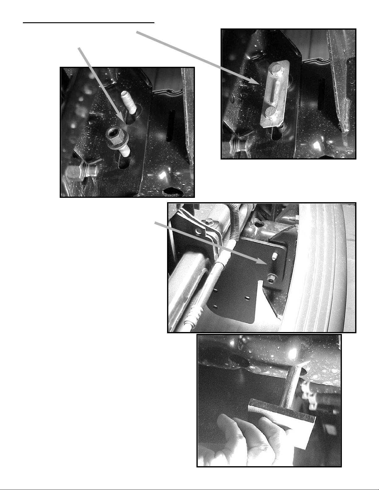
1. Remove factory bolt assembly
and reverse bolts so they are pointing inward.
2. Install R.H. and L.H Frame Mounting
Brackets (Item #3 & #4) to bolt
assembly using factory hardware.
Installing the Frame Mounting Bracket
2
3. Install 1/2-13NC x 7 3/4 LG GR5 Z/P
capscrew (Item #10), spacer (#9), flat
washer, (#6), lock washer (#8), and
nut (#7) to frame and Frame Mounting
Brackets (Item #3 & #4) on right and
left side of frame.
Page 3

6. Cut hole in air dam 3 1/4” wide x 3 1/2” high
(Height of hole will be from bottom of top lip to
top of bottom lip of air dam).
Do not cut through top or bottom lip.
7. Remove bolts from Receiver Assembly (item
#1) and lower it back down.
8. Lift front of Receiver Assembly through hole in
air dam and bolt to Frame Mounting Brackets
(Item #3 & #4) using 3 1/2-13NC x 1 1/4 LG
GR5 Z/P capscrews, nuts (Item #7), and lock
washers (#8) on right and left sides of frame.
9. Torque all bolts to proper torque values (see
chart on following page).
10.Install cover (item #2) into end of receiver
assembly (#1).
Install Receiver Assembly
4. Lift Receiver Assembly (Item #1) into
place and install top rear 1/2-13NC x 1 1/4
LG GR5 Z/P capscrew (item #5) and nut
(item #7) loosely.
Cutting the Air Dam
5. Swing Receiver Assembly up and use to
mark 3 1/4” wide hole in air dam.
3
Page 4

Parts List
Ref. Part
No. Qty No. Description
1 1 530160 Assembly - Front Receiver
2 1 472032 Cover - Front Receiver
3 1 312561 Bracket - R.H. QM Frame
4 1 312562 Bracket - L.H. QM Frame
5 6 414578 Capscrew - 1/2-13NC x 1 1/4 LG GR5 Z/P
6 2 418223 Washer - 1/2 Flat Z/P
7 8 418069 Nut - 1/2-13NC Z/P
8 8 418218 Lockwasher - 1/2 Z/P
9 2 362285 Spacer - Frame Mount
10 2 414992 Capscrew - 1/2-13NC x 7 3/4 LG GR5 Z/P
4
1
2
9
4 3
10
5
6
8 7
Torque V
alue Chart
1/4-20 5 ft-lbs 7 Nm
3/8-16 34 ft-lbs 46 Nm
1/2-13 87 ft-lbs 118 Nm
12 mm 39 ft-lbs 53 Nm
 Loading...