

Page 1
INSTALLATION INSTRUCTIONS
Y
FOR QM FRONT RECEIVER KIT #251071
ON 2001 FORD EXPLORER SPORT & SPORT TRAK
NOTICE
Ramsey kits are designed for use with Ramsey Winches only.
Use or sales of kits for other winches or applications voids warranty.
WARNING
Ramsey offers mounting kits and winches for various vehicles. In crash tests on a limited number
of automotive manufacturer's vehicles, winches/mounting kits, which have been properly
mounted, have not interfered with air bag operation.
The user/customer, or their installer, must verify that the mounting kit does not interfere with the
factory air bag sensors, which must not be relocated or modified in any way.
The user/customer should follow the vehicle manufacturer's recommendations and those of a
qualified mechanic to determine if the winch/mounting kit might interfere with the air bag
operation. The user/customer should then determine the suitability of a winch/mounting kit on a
particular vehicle.
PLEASE BE ADVISED THAT THE VEHICLE'S AIR BAG SYSTEM MAY NOT OPERATE PROPERLY IF THE
WINCH/MOUNTING KIT IS NOT MOUNTED IN COMPLIANCE WITH THE VEHICLE MANUFACTURER'S
RECOMMENDATIONS.
DO NOT ATTACH TOW HOOK TO ANY PART OF MOUNTING KIT UNLESS INSTRUCTED TO
DO SO.
DO NOT SUBSTITUTE ATTACHING HARDWARE ITEMS (BOLTS, NUTS, OR WASHERS).
READ AND UNDERSTAND WINCH OWNER'S MANUAL BEFORE INSTALLATION AND OPERATION OF WINCH.
SEE WARNING AND CAUTION.
IMPORTANT NOTES!
1. RIGHT AND LEFT HAND DIRECTIONS AS IF SEATED BEHIND STEERING WHEEL.
2. ALL FASTENING HARDWARE MUST BE LOOSELY ASSEMBLED UNTIL DIRECTED TO TIGHTEN.
RAMSEY WINCH COMPAN
P.O. BOX 581510
TULSA, OKLAHOMA 74158
KI-913362-0101-A
Page 2
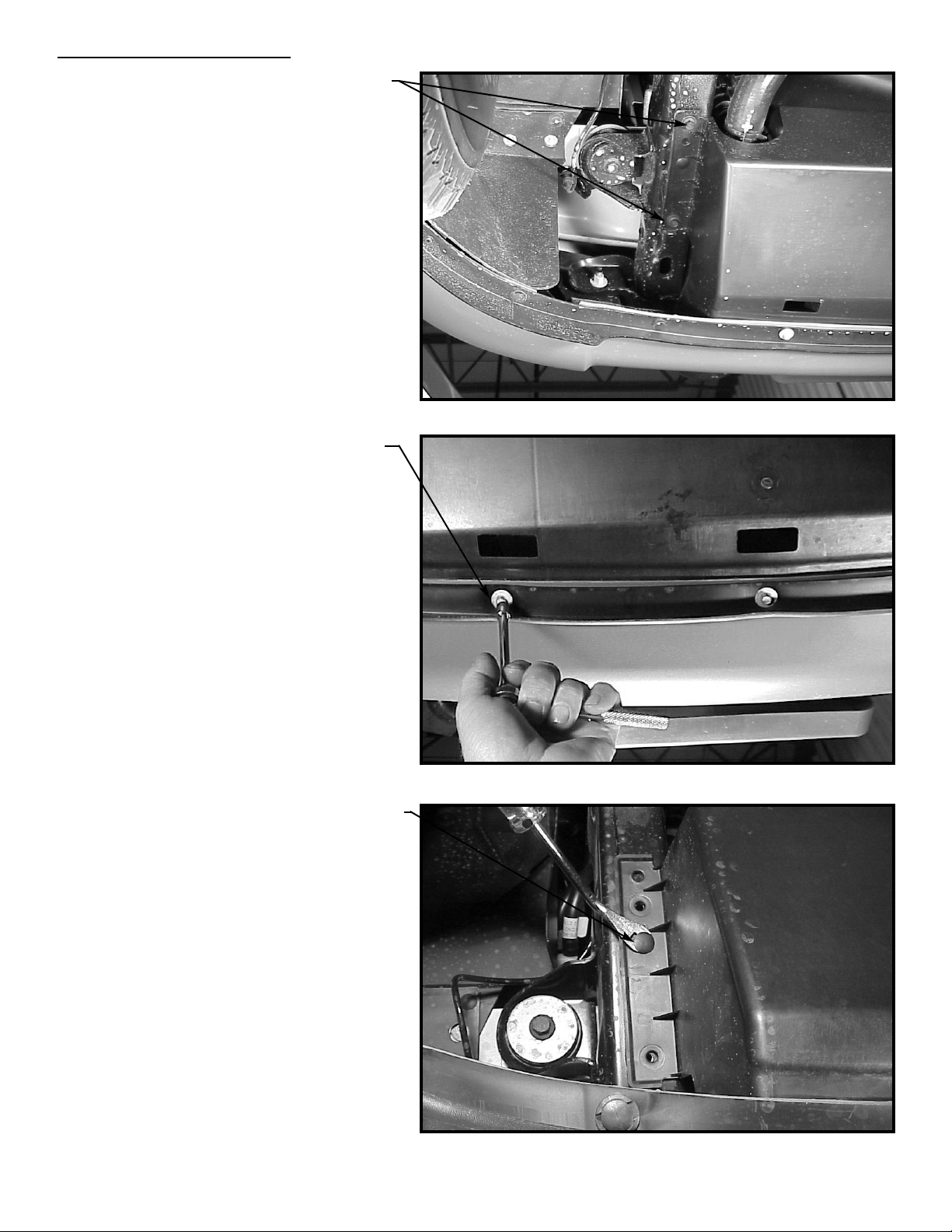
1. Remove (2) metric bolts from each
side.
3. Remove plastic fastener (1) each side
and lift off the splashguard.
2. Remove (3) metric bolts across the
front.
Removing the Splashguard
1
Page 3

1. Remove and discard the (2) factory
tow hook bolts from the tow hooks
on each side.
2. Remove tow hooks and set aside.
Removing the Tow Hooks
1. Notch metal bumper brace in center of
vehicle. Cutout should be 3” wide by
1/2” deep.
Installing the Frame Tube Assembly
2
1. Slide the frame tube assembly in
place from the back side of the
air dam.
2. Work the frame tube assembly in position behind the transmission oil cooler
lines as shown in the photograph.
3. Install new 12mm x 1.75 bolt through
rear hole. Secure with 1/2” lockwasher and 1/2” flat washer. Tighten 2-3
turns only. Repeat for other side.
Installing the Frame Tube Assembly
3”
1/2”
Page 4

1. Slide the tow hooks through the tow
hook access in the air dam.
2. Position slot in tow hook over the
rear 12mm bolt and slide forward.
3. Install new front tow hook bolt
(12mm x 1.75). Secure with 1/2”
lockwasher and 1/2” flat washer.
Tighten all bolts securely. (See torque
value chart on page 3).
4. Repeat for other side.
Reinstalling the T
ow Hooks
3
1. Using existing access space in air
dam, slide the receiver tube through
the air dam from the front. Align holes
in receiver tube with holes in frame
mounting bracket.
Note: On some vehicles, it may be
necessary to slightly notch the
bottom edge of the license tag
holder.
2. Secure back plate using (2) 3/8” X
1” capscrews, with 3/8” lockwasher
and nut each side. Tighten securely.
(See torque value chart on page 4).
3. Secure top plate using (2) 3/8” X
1” capscrews, with 3/8” lockwasher
and nut each side. Tighten securely.
(See torque value chart on page 4).
4. Refer to winch owner’s manual for
mounting instructions.
Install Receiver T
ube
Page 5

1. Place splashguard in position and
replace the (2) factory supplied
metric bolts each side.
2. Replace (3) metric bolts across the
front.
3. Replace plastic fastener (1) each
side.
Reinstalling the Splashguard
Parts List
1 4 414314 Capscrew-3/8-16NCX1” Lg
2 4 415313 Capscrew M12X1.75X55MM Lg
3 4 418035 Hex Nut-3/8-16NC, Z/P
4 4 418177 Lockwasher-3/8 Med Sect, Z/P
5 4 418218 Lockwasher-1/2 ID Med Sect
6 4 418221 Washer-1/2 SAE Flat
7 2 440138 Cable Ties
8 1 472032 Receiver Cover
9 1 530151 Receiver Tube
10 1 530152 Frame Mounting Tube
Torque Value Chart
1/4-20 5 ft-lbs 7 Nm
3/8-16 34 ft-lbs 46 Nm
1/2-13 87 ft-lbs 118 Nm
12 mm 39 ft-lbs 53 Nm
OM-913362-0101-A
4
 Loading...