

Page 1
CAUTION: Read and understand this manual before installation and operation of winch. See Safety Precautions!
Congratulations
You have purchased the finest winch available in its service
class. It features a highly efficient 3 stage planetary gear set
which transmits torque from a series wound DC motor. A safe
positive clutch allows free spooling for quick cable deployment.
An automatic load holding brake is designed to hold the fully
rated capacity of the winch. It was designed and manufactured
to provide you with the utmost in utility. As with any device that
combines power and movement in its use, there are dangers if
improperly used. At the same time, there are easier ways for
getting the job done if certain precautions are taken first.
Please read this manual carefully. It contains useful ideas in
obtaining the most efficient operation from your Ramsey Winch
and safety procedures you need to know before beginning use.
When you follow our guidelines for operation, your Ramsey
Winch will give you many years of satisfying service. Thank
you for choosing Ramsey. You will be glad you have one working for you.
Ramsey Winch Company
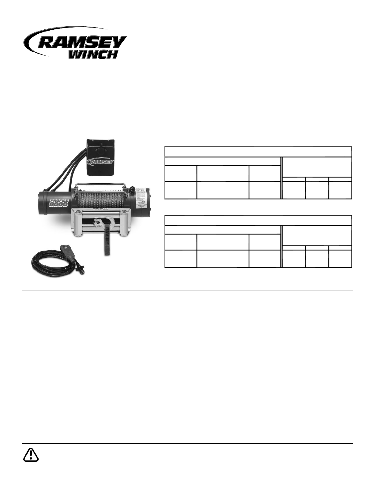
Owner’s Manual
Front Mount Electric Winch
Model Profile 6000T
Model Profile 8000T
Table of Contents
Performance Specifications . . . . . . . . . . . . . . . . .Front Cover
Safety Precautions . . . . . . . . . . . . . . . . . . . . . . . . . . . . . . .2
Tips for Safe Operation . . . . . . . . . . . . . . . . . . . . . . . . . . . .2
Techniques of Operation . . . . . . . . . . . . . . . . . . . . . . . . . . .3
Installation . . . . . . . . . . . . . . . . . . . . . . . . . . . . . . . . . . . .4-7
Operating Instructions . . . . . . . . . . . . . . . . . . . . . . . . . . . . .8
Electrical Connections and Operation . . . . . . . . . . . . . . . . . .8
Maintenance . . . . . . . . . . . . . . . . . . . . . . . . . . . . . . . . . . . .8
Troubleshooting Guide . . . . . . . . . . . . . . . . . . . . . . . . . . . . .9
Winch Parts List . . . . . . . . . . . . . . . . . . . . . . . . . . . . .10-12
Warranty . . . . . . . . . . . . . . . . . . . . . . . . . . . . . . .Back Cover
Intended purpose for Ramsey Profile 6000T and Profile
8000T Series Winches: Vehicle Recovery and Pulling of
Loads.
Noise Level 79 dB(A)
Noise Level 84 dB(A)
CURRENT
(Approx.)
(AMP)
LINE PULL
-0-
(lbs.)
3,000
3,370
1,000
-0-
(Kn)
15
13,34
4,44
OF CABLE
PERFORMANCE FIRST LAYER
(Approx.)
LINE SPEED
(FPM)
18
20
23
45
12V
5.5
6.1
13.7
(MPM)
12V
7
CABLE DRUM CAPACITY
BY LAYER
7,0mm dia. wire rope).
(based on recommended
LAYER
303
270
200
100
12V
2
1
3
4
45
19
Ft.
98
75
14
30
23
6
M
4,000
2,000
-0-
4,940
17,79
8,89
-0-
22 11
13
18
35
3.4
5.5
10.7
4
CABLE DRUM CAPACITY
8,0mm dia. wire rope).
(based on recommended
BY LAYER
333
270
210
95
2
1
3
45
19
65
14
20
6
PERFORMANCE FIRST LAYER
OF CABLE
CURRENT
(Approx.)
(AMP)
12V
(MPM)
12V
LINE SPEED
(Approx.)
(FPM)
12V
LINE PULL
(lbs.) (Kn)
LAYER
Ft.
M
Profile 6000T
Profile 8000T
Page 2

Safety Precautions
To Guard against Possible Injury...
A minimum of five wraps of cable around the drum
barrel is necessary to hold the rated load. Cable
clamp is not designed to hold the load.
A. Keep yourself and others a safe distance to the side of the
cable when pulling under load.
B. Do not step over a cable, or near a cable under load.
C. Use supplied hook strap when handling hook for spooling
wire rope.
D. Do not move the vehicle to pull a load on the winch cable.
This could result in cable breakage and/or winch damage.
E. Use a heavy rag or gloves to protect hands from burrs
when handling winch cable.
F. Apply blocks to wheels when vehicle is on an incline.
G. Winch clutch should be disengaged when winch is not in
use and fully engaged when in use.
H. Modification, alteration, or deviation to the winch should
only be made by Ramsey Winch Company.
I. Keep the duration of your pulls as short as possible. If the
motor becomes uncomfortably hot to the touch, stop and
let it cool for a few minutes. Do not pull more than one
minute at or near rated load. Do not maintain power to the
winch if the motor stalls. Electric winches are for intermit-
tent usage and should not be used in constant duty appli-
cations.
J. Disconnect the remote control switch from the winch
when not in use. A safety on-off switch in your vehi-
cle is required.
K. NOTE: Do not use winch in hoisting applications due to
required hoist safety factors and features.
L. An overload device is required to prevent winch from
exceeding maximum line pull ratings shown in tables.
M. To respool correctly, it is necessary to keep a slight load
on the cable. This can be accomplished by (wearing
gloves) holding the cable with one hand and the remote
control switch with the other, starting as far back and in
the center as you can, walking up keeping load on the
cable as the winch is powered in. Do not allow the cable
to slip through your hand and do not approach the winch
too closely. Turn off the winch and repeat the procedure
until all the cable except a few feet is in. Disconnect the
remote control switch and finish spooling in cable by rotating the drum by hand with clutch disengaged. On hidden
winches, spool in cable under power using supplied hook
strap.
Tips for Safe Operation
Do not underestimate the potential danger in winching operations. Neither should your fear them. Do learn the basic dangers and avoid them.
Observe the spooling of cable onto drum. Side pulls can
cause cable to pileup at one end of the drum. To correct
uneven stacking, spool out that section of the cable and move
it to the other end of the drum and continue winching. Uneven
spooling which causes cable pileup can interfere with the
solenoid housing causing damage to the winch.
Store the remote control switch inside your vehicle where it
will not become damaged. Inspect it before you plug it in.
When ready to begin spooling in, plug in remote control
switch with clutch disengaged. Do not engage clutch with
motor running.
Never connect the hook back to the cable. This causes cable
damage. Always use a sling or chain or suitable strength.
Observe your winch while winching, if possible, while standing at a safe distance. If you use vehicle drive to assist, stop
and get out every few feet to assure the cable is not piling up
in one corner. Jamming cable can break your winch.
Do not attach tow hooks to winch mounting apparatus. They
must attach to vehicle frame.
When double lining during stationary winching, the winch
hook should be attached to the chassis of the vehicle.
Since the greatest pulling power is achieved on the innermost
layer of your winch, it is desirable to pull off as much line as
you can for heavy pulls. If this is not practical, use a snatch
block and double the arrangement (see illustration).
Remember, a minimum of 5 wraps of cable around the drum
barrel is necessary to hold the rated load.
Neat, tight spooling avoids cable binding which is caused
when a load is applied and the cable is pinched between two
others. If this happens, alternately power the winch in and out
a few inches. Do not attempt to work a bound cable under
load, free by hand.
2
Page 3
Techniques of Operation
The best way to get acquainted with how your winch
operates is to make a few test runs before you actually
need to use it. Plan your test in advance. Remember
you hear your winch as well as see it operate. Get to
recognize the sound of a light steady pull, a heavy pull,
and sounds caused by load jerking or shifting. Soon you
will gain confidence in operating your winch and its use
will become second nature with you.
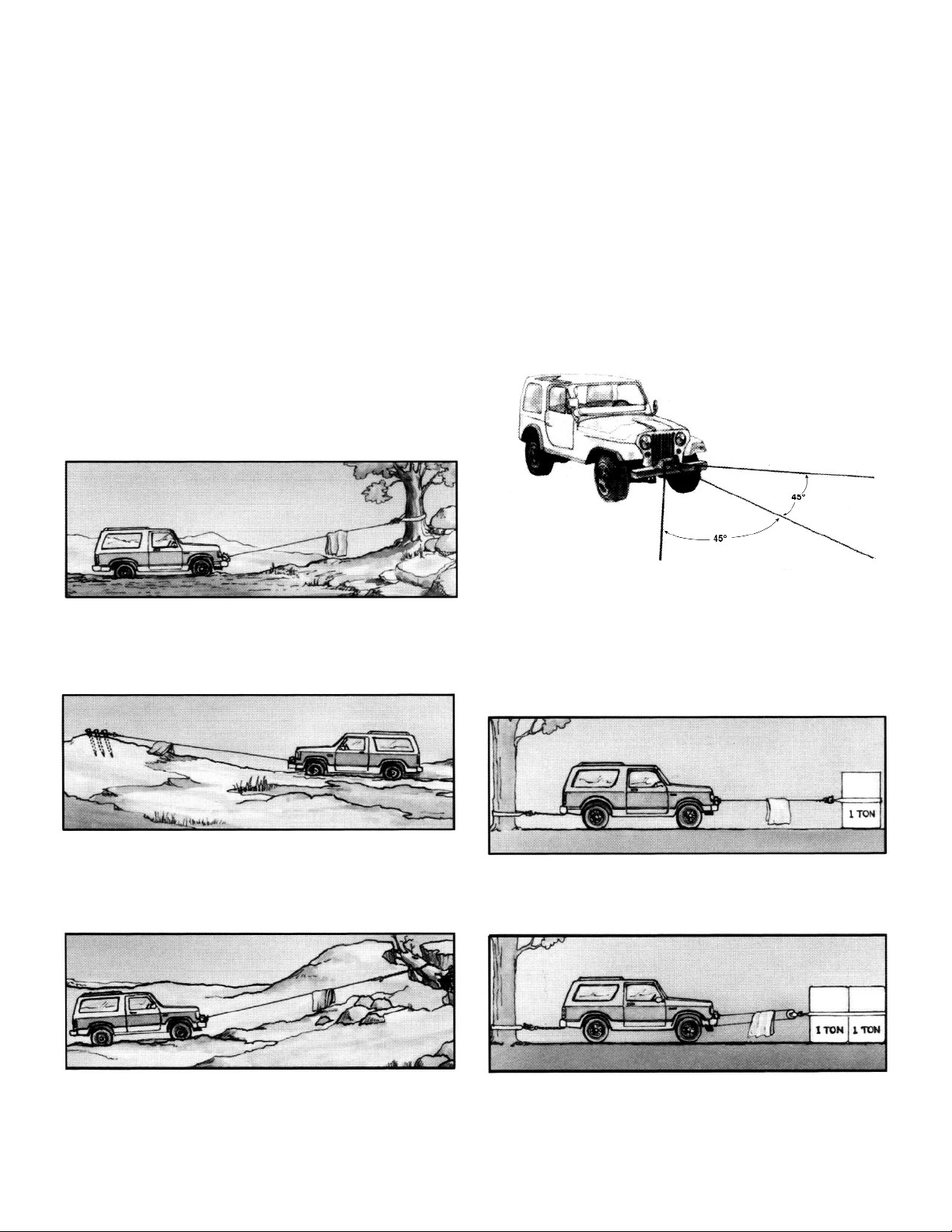
Your winch will not only pull your vehicle up or ease your
vehicle down a steep grade, it will also pull another vehicle or a load while your vehicle is anchored in a stationary position. The sketches on this page show you a few
techniques.
When pulling a heavy load, place a blanket, jacket or tarpaulin over the cable five or six feet from the hook. It
will slow the snap back in the event of a broken cable.
Also, open the vehicle hood for additional protection.
Use the vehicle wheel power to help the winch, but don't
overtake the winch line. Plan your pull. You can't
always hook up and pull out in one step. Examine all the
areas for anchoring possibilities as well as leverage situations, direction, and goal.
For basic self-recovery, anchor to a tree or heavy rock.
When anchoring to a tree, always use a tree trunk protector.
Stakes driven in solid earth and chained together make a
good anchor point for self-recovery when no solid
anchor point is available.
For a solid anchor, bury a log with earth or sand or place
it in a deep ravine.
Winches equipped with cable guide fairleads can pull
from several directions. Pull from an angle only to
straighten up the vehicle-otherwise you can damage
structural members or other parts of your vehicle and
cause excess cable buildup on one end of the winch
drum.
For a direct pull of 2000 lbs., hitch truck to a tree or
solid anchor, and take out of gear.
To double the pull, use 2-part line and tie off to chassis.
Take out of gear.
3
Page 4
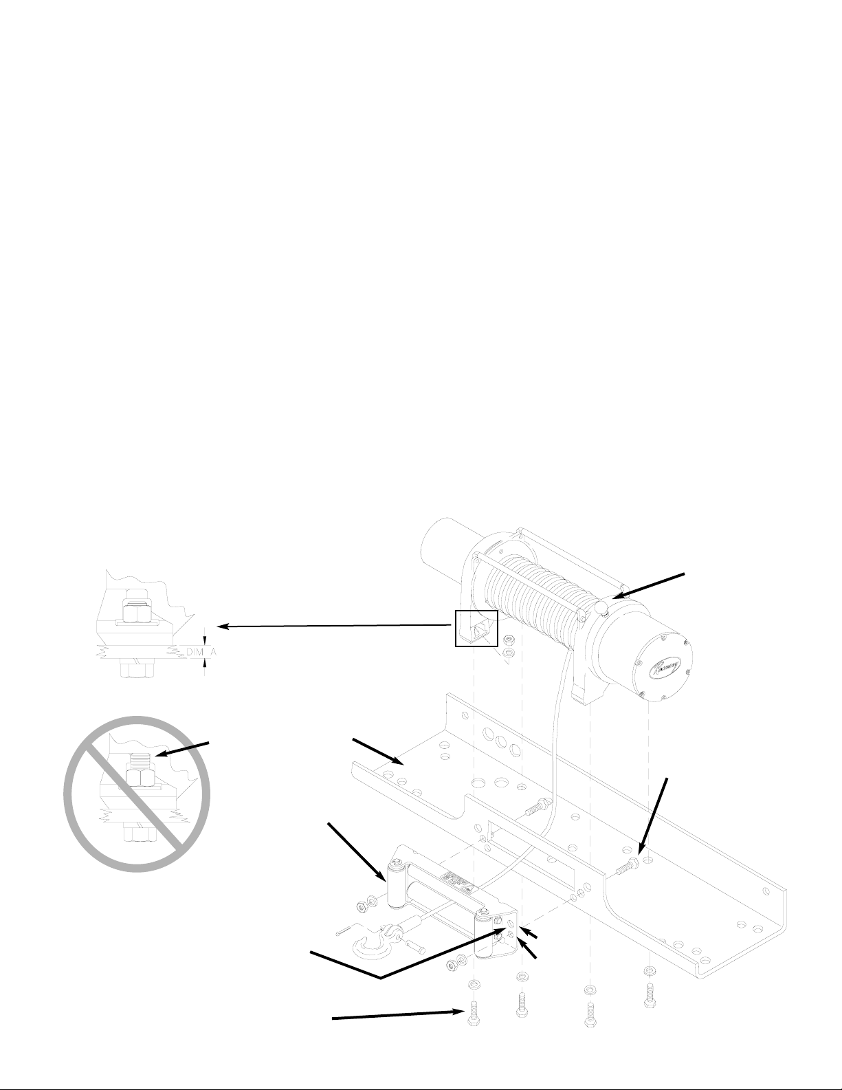
** TO ENSURE PROPER ALIGNMENT
OF FAIRLEAD TO THE DRUM, USE
THE SMALLER DIA. SET OF HOLES
FOR MOUNTING.
WINCH MOUNTING BOLT
3/8-16NC X 1-1/4” LG.
FAIRLEAD MOUNTING
BOLT
3/8-16NC X 1-1/4” LG.
MOUNTING
CHANNEL
ROLLER
FAIRLEAD
1/2” DIA.
7/16” DIA.
*
Installation
The winch shown in this owner’s manual is solely and exclusively designed for vehicle mounted, non-industrial applications. All other applications will void warranty.
NOTE: For specific bull-bar applications, the shifter lever on
the winch may need to be repositioned. Refer to pages 6-7 for
instructions in how to do this.
It is very important that the winch be mounted on a flat surface so that the three major sections (the motor end, the cable
drum, and the gear housing end) are properly aligned. It is
recommended that Ramsey kits be used to mount the winch.
They are designed to align the winch and distribute up to the
full rated load evenly, to avoid possible damage to the winch
or vehicle.
NOTE: If recommended mounting is not used, a kit of equal
design must be used.
Also available for mounting the Profile 6000T and 8000T are
the following winch mounting channels:
• #251126 short length (23.63”) black
• #251127 medium length (30.00”) black
• #251128 long length (36.00”) black
It is recommended that Ramsey mounting channels be used
with all non-Ramsey mounting.
For mounting the winch with a standard mounting channel,
such as those available from Ramsey, use (4) 1-1/4” long
mounting bolts as shown below.
* In specific Bull Bar installations, (2) 1-3/4” long bolts
(included) may need to be substituted for 1-1/4” bolts to
mount the winch properly. Refer to Detail A below: if the
mounting thickness (dimension A) is .25” or less, use 11/4” long bolts. If dimension A is greater than .25”, you
should use 1-3/4” long bolts. If dimension A is between
.25” and .56”, washers may need to be added to the 13/4” bolts to prevent the end of the bolt from hitting the
winch foot, as shown in Detail B.
Do not use the longer bolts unless needed. Using bolts
that are too long may cause damage to the winch. After
tightening mounting bolts, confirm that they have sufficient
clearance (see Detail B) above the end of the bolt. Some
thread should be visible above the nut.
** For mounting to Bull Bar, the roller fairlead may need to
be rotated 180° to ensure proper alignment to drum.
CLUTCH SHIFTER
KNOB
DETAIL A
DETAIL B
4
INSUFFICIENT
CLEARANCE
Page 5

5
Attach fairlead to channel using hardware furnished with
winch. Attach winch to channel. Thread capscrews with
lockwashers through mounting holes in channel and into
winch feet (see Figure previous page).
Substitution of attaching hardware items (bolts, nuts or
washers) different from those supplied with your winch
and mounting kit can lead to failure causing damage or
serious injury (use SAE grade 5 bolts or better and
torque to 34 ft.lbs.).
Place end of wire rope through fairlead and attach cable
hook. Use clevis pin and cotter pin.
To mount Solenoid Assembly, use included Solenoid
Mounting Bracket. Mount bracket to tie bar using (1)
1/4-20NC x 1” capscrew in place of 3/4” tie bar capscrew. Install bracket to back of solenoid using included
nuts and lockwashers.
When mounting winch, connect labeled motor leads
coming from solenoid assembly to appropriately marked
motor terminals as shown lower right. Tighten nuts on
motor terminals securely. Attach solenoid ground wire
to ground bolt located at bottom of motor (Battery
ground wire is already installed to grounding bolt on
motor).
2
1
A
View A-A
A
A
Page 6

Repositioning Shifter for Specific Bull Bar Applications
Note: The shifter is positioned correctly for most applications. It will only need to be repositioned as necessary for
specific bull bar applications.
Refer to the Parts List and Exploded Parts Diagram for your specific winch elsewhere in this owner’s manual.
1. Position winch as shown in Figure 1. Remove screws from tiebars. You may be able to loosen the screws at the
motor end without removing them. Pull the Gear Housing assembly from the drum and shaft and set it down on
the work bench with the Gear Housing Cover up. Remove the drum bushing from the Gear Housing assembly or
the end of the drum. Set aside.
2. Remove (6) capscrews
from the Gear Housing
Cover. Holding the Gear
Housing Cover over the
Gear Housing assem-
bly, flip it over and set it
on the workbench.
3. Gently lift the Gear Housing assembly,
working the gears, bushings, etc. that
are inside the Gear Housing out so that
they are left stacked on the workbench.
See Figure 2.
4. Turn the Gear Housing assembly over
and set on workbench. Remove the
Retainer (item #37) by removing six
capscrews (item #21) from Gear End
Bearing (item 13). Once the retainer is
removed, the Ring Gear (item #10),
Cam Ring (item #36), and Locking Ring
(item #34) can be lifted off the end
bearing.
Remove the six springs (item #38) from
the end bearing.
Figure 2
Figure 3
Figure 1
6
Page 7

5. Determine position shifter knob needs to be for
your application. Note: Shifter knob cannot be
positioned too low or it will interfere with the feet
on the Gear End Bearing (see Range of Position in
Figure 4).
6. To position the shifter knob, place locking ring in
end bearing with stop post approximately 180°
from where shifter knob needs to be positioned.
Place cam ring over locking ring in proper position and confirm that shifter knob will move from
engaged to disengaged position without interference. Mark position of stop post on end bearing.
7. Remove cam ring and locking ring from end bearing. Insert springs (item #38) into end bearing. When you
replace the locking ring (item #34) over the springs, be sure the springs compress down into their recesses,
and don’t bend sideways.
8. Reassemble Gear Housing as shown in Figure 3. Make sure locking ring is positioned with stop post at marked
location. The capscrews (item #38) for the retainer should be tightened to 40-45 in-lbs. Do not over-tighten.
9. Place Gear Housing over the stacked gears, etc. that you removed in step 3. Gently work the housing over the
stack, turning it as needed to mesh the planetary gears with the ring gear in the housing. Once they are all in the
housing, flip the assembly over. Align the Gear Housing Cover and gasket with the holes in the ring gear. Replace
the (6) capscrews that hold the Gear Housing Cover onto the Gear Housing. Tighten securely.
10. Move the Shifter to the Disengaged position.
11. Turn the Gear Housing over and set it on the work
bench with the Gear Housing Cover down. See
Figure 5.
12. Install the drum bushing into the Gear Housing, con-
firming that the slot in the bushing is aligned with
the key in the end bearing. Pick up the rest of the
winch (drum and motor end), and holding the drum,
lower the winch onto the gear end. Stab the shaft
into the gear end--you may need to turn the drum
slightly to get the shaft to go all the way in.
13. Place the tiebars on the motor end and gear end and
fasten using (4) screws. Tighten securely.
14. Once the winch is reassembled, turn it so that it is
sitting on its feet. Confirm that the cable will
freespool when the shifter is in the Disengaged position. Connect up the winch temporarily and confirm
that the cable spools when the shifter is in the
Engaged position.
Figure 4
Figure 5
7
Page 8

Operating Instructions
The winch clutch allows rapid unspooling of the wire rope for
hooking onto the load or anchor point. The clutch is operated
by the shifter knob located on the gear housing end of the
winch as follows:
1. To disengage the clutch, move the clutch shifter knob to
the “OUT” position. Wire rope may now be freespooled off
the drum.
2. To engage the clutch, move the clutch shifter knob into the
“IN” position. The winch is now ready for pulling.
Electrical Connections and Operations
For normal self-recovery work, your existing electrical system
is adequate. Your battery must be kept in good condition. A
fully charged battery and proper connections are essential.
Run the vehicle engine during winching operations to keep
battery charged.
An emergency stop switch (reference Ramsey part no.
282053) is required between the positive (+) battery terminal
and the red winch cable. An overload device is required to prevent winch from exceeding the rated line pull.
Route battery cables up to battery.
C
AUTION: BE SURE BATTERY CABLES ARE NOT DRAWN TAUT ACROSS
ANY SURFACES WHICH COULD POSSIBLY DAMAGE THEM
.
Connect red cable to positive (+) battery terminal. Connect
black ground cable to negative (-) terminal of battery (See
Figure page 5).
Models Equipped with Push Button Remote Control
Switch
The remote control switch is water proof. It has push buttons
on either side. Make sure the motor has stopped fully before
reversing. To actuate winch simply plug remote control switch
into receptacle in cover of winch. Run winch forward and
reverse to check directions. Snap appropriate “IN” and “OUT”
disc into proper thumb cavity. Do not leave switch plugged
in when winch is not in use.
Models Equipped with Wireless Remote Control
See Installation and Operating Instructions for Ramsey
Universal Remote Control (OM-914057) included with the
wireless remote.
Maintenance
All moving parts in the winch are permanently lubricated with
high temperature lithium grease at the time of assembly.
Under normal conditions factory lubrication will suffice.
Lubricate cable periodically using light penetrating oil. Inspect
the cable for broken strands and replace if necessary. If the
cable becomes worn or damaged, it must be replaced.
Corrosion on electrical connections will reduce performance or may cause a short. Clean all connections especially in the remote control switch and receptacle. In
salty environments use a silicone sealer to protect from
corrosion.
To minimize corrosion of the internal motor components that
may occur due to condensation, power the winch in or out
periodically. Energizing the motor will generate heat, which will
help dissipate any moisture buildup in the motor. This should
be performed at periodic intervals (such as with each oil
change to your vehicle). Note:
Refer to the Troubleshooting
Guide if the motor has been submerged.
Cable Installation
1. Unwind the new cable by rolling it out along the ground to
prevent kinking.
2. Remove old cable and observe the manner in which it is
attached to the cable drum flange.
3. Before installing the new cable assembly, securely wrap
the end of the cable with plastic tape or similar tape to prevent fraying.
4. Position the cable drum so that the large 13/32” diameter
hole in the motor end drum flange is approximately on the
top.
5. Form a short bend (approximately 1/2” long) in the end of
the cable. Insert the bend into the 13/32” hole in the drum
flange and then carefully run the winch in the “reel in”
direction approximately 3/4 revolution until the 1/4” diameter threaded hole in the drum flange is on top.
6. Secure the cable to the drum flange using cable anchor
and capscrew shown in the parts drawing on page 10
(Item nos. 20 and 30). Securely tighten the capscrew, but
do not over-tighten.
7. Wind 5 wraps of cable onto the drum. Wind on the rest of
the cable by pulling in a light load to keep the tension constant. Allow the cable to swivel by using a length of chain
or a swivel block between the cable hook and the load.
8
Page 9

Troubleshooting Guide
9
Condition Possible Cause Correction
Defective or stuck
solenoid
Jar each solenoid to free contacts. Check each solenoid
by applying 12 volts to coil terminal (it should make an
audible click when energized).
Defective remote control
switch
Disengage winch clutch, remove remote control switch
plug from the socket and jump pins at 8 and 4 o'clock.
Motor should run. Jump pins at 8 and 10 o'clock. Motor
should run.
Long period of operation Cooling off periods are essential to prevent overheating.
Insufficient battery
Check battery terminal voltage under load. If 10 volts or
less, replace or parallel another batter to it.
Bad connection Check battery cable for corrosion; clean and grease.
Insufficient charging
system
Replace with larger capacity charging system
MOTOR RUNS, BUT
DRUM DOES NOT TURN
Clutch not engaged
If clutch engaged but symptom still exists, it will be
necessary to disassemble winch to determine cause and
repair.
Defective or stuck
solenoid
Jar each solenoid to free contacts. Check each solenoid
by applying 12 volts to coil terminal (it should make an
audible click when energized).
Defective remote control
switch
Disengage winch clutch, remove remote control switch
plug from the socket and jump pins at 8 and 4 o'clock.
Motor should run. Jump pins at 8 and 10 o'clock. Motor
should run.
Defective motor
If solenoids operate, check for voltage at armature post;
replace motor.
Loose Connections
Tighten connections on bottom side of hood and on
motor.
MOTOR WATER
DAMAGED
Submerged in water or
water from high pressure
car wash
Allow to drain and dry thoroughly, then run motor without
load in short bursts to dry windings.
MOTOR RUNS IN ONLY
ONE DIRECTION
MOTOR RUNS
EXTREMELY HOT
MOTOR RUNS, BUT
WITH INSUFFICIENT
POWER, OR WITH LOW
LINE SPEED.
MOTOR WILL NOT
OPERATE
Page 10

Profile 6000T
10
21
19
7
22
25
**18
27
26
35
26
8
15
35
6*
36
19
44
43
34
10
38
13
24
32
1
40
29
28
15
11
9
30
20
3
41
12
39
17
23
16
2
40
5
37
31
33
42
Item
No.
Qty. Part No. Description
Item
No.
Qty. Part No. Description
1 1 247024 GEAR CARRIER ASSY - INPUT 23 6 416273 SCREW #6-32NC X 3/8 LG FIL HD F/B
2 1 247006 GEAR CARRIER ASSY - OUTPUT 24 1 418029 NUT 5/16-18NF HX JAM PLTD
3 1 247007 GEAR CARRIER ASSY - INTERMEDIATE 25 4 418035 NUT 3/8-16NC HX REG PLTD
4 1 278189 SOLENOID ASSY 26 5 418177 LOCKWASHER-3/8 ID MED SECT PLTD
5 1 289141 CABLE ASSY - GROUND 27 4 418181 WASHER-FLAT 3/8 ID SAE PLTD
*6 1 251110 SWITCH ASSY 28 1 442207 GASKET-COVER
7 1 251187 CABLE ASSY - 1/4 DIA. X 100' 29 1 444048 GEAR-OUTPUT SUN
8 1 296553 BRAKE/SHAFT ASSY 30 1 448071 CABLE ANCHOR
9 1 332128 DRUM-CABLE 31 1 296570 MOTOR
10 1 334143 GEAR-RING 32 1 452001 KNOB-SHIFTER
11 1 334147 GEAR-INTERMEDIATE SUN 33 1 470053 ROLL PIN 1/8 DAI X 3/8 LG
12 1 444097 GEAR-INPUT SUN 34 1 477002 LOCKING RING
13 1 338332 END BEARING-GEAR HOUSING 35 2 477004 RING-HALF
14 NOT USED 36 1 477011 CAM RING
15 2 412056 BUSHING-DRUM 37 1 479007 RETAINER-RING GEAR
16 1 412061 BUSHING-SHAFT 38 6 494077 SPRING
17 1 413018 COVER-GEAR HOUSING 39 2 518019 THRUST WASHER
**18 4 414316 CAPSCREW 3/8-16NC X 1-1/4 LG HX HD GR5 PLTD 40 2 519020 THRUST WASHER
2 414317 CAPSCREW 3/8-16NC X 1-3/4 LG HX HD GR5 PLTD 41 1 518027 THRUST DISC
19 4 414823 CAPSCREW 1/4-20NC X 3/4 LG SOC BUTT HD F/B 42 2 448049 TIE BAR
20 1 414830 CAPSCREW 1/4-20NC X 3/8 LG BUTT HD 43 1 408315 SOLENOID MOUNTING BRACKET
21 6 414861 CAPSCREW 1/4-20NC X 3/4 LG FLAT SOC HD NYLOK 44 1 414829 CAPSCREW 1/4-20NC X 1" SOC BUTTON HD
22 1 414370 CAPSCREW 3/8-24NFX X 1/2 HX HD GR5 Z/P
Profile 6000T Winch Parts List
* Switch assembly included on certain models.
** See page 4 Installation for determination of correct bolt.
Page 11

Profile 8000T
11
Item
No.
Qty. Part No. Description
Item
No.
Qty. Part No. Description
1 1 247024 GEAR CARRIER ASSY - INPUT 23 6 416273 SCREW #6-32NC X 3/8 LG FIL HD F/B
2 1 247005 GEAR CARRIER ASSY - INTERMEDIATE 24 1 418029 NUT 5/16-18NF HX JAM PLTD
3 1 247008 GEAR CARRIER ASSY - OUTPUT 25 4 418035 NUT 3/8-16NC HX REG PLTD
4 1 278189 SOLENOID ASSY 26 5 418177 LOCKWASHER-3/8 ID MED SECT PLTD
5 1 289141 CABLE ASSY - GROUND 27 4 418181 WASHER-FLAT 3/8 ID SAE PLTD
*6 1 251110 SWITCH ASSY 28 1 442207 GASKET-COVER
7 1 251186 CABLE ASSY - 5/16 DIA X 95' 29 1 444048 GEAR-OUTPUT SUN
8 1 296553 BRAKE/SHAFT ASSY 30 1 448046 CABLE ANCHOR
9 1 332128 DRUM-CABLE 31 1 452001 KNOB-SHIFTER
10 1 334143 GEAR-RING 32 1 296570 MOTOR
11 1 334145 GEAR-INTERMEDIATE SUN 33 1 470053 ROLL PIN 1/8 DIA X 3/8 LG
12 1 444097 GEAR-INPUT SUN 34 1 477002 LOCKING RING
13 1 338332 END BEARING-GEAR HOUSING 35 2 477004 RING-HALF
14 NOT USED 36 1 477011 CAM RING
15 2 412056 BUSHING-DRUM 37 1 479007 RETAINER-RING GEAR
16 1 412061 BUSHING-SHAFT 38 6 494077 SPRING
17 1 413018 COVER-GEAR HOUSING 39 2 518019 THRUST WASHER
**18 4 414316 CAPSCREW 3/8-16NC X 1-1/4 LG HX HD GR5 PLTD 40 2 519020 THRUST WASHER
2 414317 CAPSCREW 3/8-16NC X 1-3/4 LG HX HD GR5 PLTD 41 1 518027 THRUST DISC
19 4 414823 CAPSCREW 1/4-20NC X 3/4 LG SOC BUTT HD F/B 42 2 448049 TIE BAR
20 1 414830 CAPSCREW 1/4-20NC X 3/8 LG BUTT HD 43 1 408315 SOLENOID MOUNTING BRACKET
21 6 414861 CAPSCREW 1/4-20NC X 3/4 LG FLAT SOC HD NYLOK 44 1 414829 CAPSCREW 1/4-20NC X 1" SOC BUTTON HD
22 1 414370 CAPSCREW 3/8-24NFX X 1/2 HX HD GR5 Z/P
Profile 8000T Winch Parts List
21
19
7
22
25
**18
27
26
35
26
8
15
35
6*
36
19
44
43
34
42
10
38
13
24
32
1
40
29
28
15
11
9
30
20
2
41
12
39
17
23
16
3
40
5
37
32
33
* Switch assembly included on certain models.
** See page 4 Installation for determination of correct bolt.
Page 12

Solenoid Assembly Parts List
278189 (Profile 6000T & 8000T)
12
Item
No.
Qty. Part No. Description
Item
No.
Qty. Part No. Description
1 1 204281 ASSEMBLY - SOLENOID BRACKET 9 4 416216 SCREW - #10-24NC X 1/2 LG
2 1 289015 ASSEMBLY - WIRE BATTERY CABLE 72" LG 10 10 418014 NUT - HX 1/4-20NC REG Z/P
3 2 289077 ASSEMBLY - WIRE #6 GA X 4.5" BLACK 11 8 418149 LOCKWASHER - 1/4 MED SECT Z/P
4 3 289170 ASSEMBLY - WIRE #2 GA X 29" MTR LEAD 12 2 418514 SPACER - SOLENOID BRACKET
5 1 296594 COVER ASSEMBLY 13 2 440260 STRAP - COPPER
6 1 408271 BRACKET - SOLENOID MOUNTING 14 4 440262 SOLENOID
7 6 414042 CAPSCREW 1/4-20NC X 5/8" HX HD 15 1 440281 ASSEMBLY - WIRE GROUND
8 2 414062 CAPSCREW 1/4-20NC X 1-1/2" GR5 Z/P 16 1 472069 GROMMET
Roller Fairlead
#251183
Included with Profile 6000T & 8000T winches.
Mounting hardware for roller fairlead included
with winch.
Page 13

Warranty Information
Ramsey Winches are designed and built to exacting specifications. Care and skill go into every winch we make. If
the need should arise, warranty procedure is outlined on the back of your self-addressed postage paid warranty
card. Please read and fill out the enclosed warranty card and send it to Ramsey Winch Company. If you have problems with your winch, please follow instructions for proper service on all warranty claims.
Ramsey Winch Company
P.O. Box 581510 - Tulsa, OK 74158-1510 USA - Phone: (918) 438-2760 - Fax (918) 438-6688
Visit us at http://www.ramsey.com
OM-914138-0804-C
Limited Lifetime Warranty
Ramsey Winch offers a limited lifetime warranty for each new Ramsey consumer/RV
winch against manufacturing defects in
workmanship and materials on all mechanical components.
Warranty registration cards for each winch
must be submitted at the time of purchase
or within 30 days. Warranty will only be
valid for the original purchase of the winch
and installed on the vehicles with which they
were originally registered.
New cable assemblies are warranted against
defects in workmanship and materials. No
warranty applies after initial use.
All Ramsey mounting kits and other accessories carry a 1-year limited warranty
against defects in material and workmanship.
This warranty is void if winch is used in
commercial/industrial applications other than
front mount self-recovery.
Electrical components consisting of motors,
solenoids, wiring, wire connectors and
associated parts carry a 1-year limited warranty. Battery isolators carry a 90-day limited warranty.
The obligation under this Warranty, statutory
or otherwise, is limited to the replacement or
repair at the manufacturer’s factory, or at a
point designated by the manufacturer, upon
inspection of such part, to have been defective in material or workmanship. This
Warranty does not obligate Ramsey Winch
Company to bear the cost of transportation
charges in connection with the replacement
or repair of defective parts, nor shall it apply
to a product upon which repairs or alterations have been made, unless authorized
by the manufacturer, or for equipment misused, neglected, or improperly installed.
IMPORTANT NOTICE: To the fullest
extent permitted by applicable law, the
following are hereby excluded and disclaimed: 1. All warranties of fitness for
a particular purpose; 2. All warranties
of merchantability; 3. All claims for consequential or incidental damages. There
are no warranties that extend beyond
the description that appears on the face
hereof.
Some states do not allow the above
exclusions or disclaimers in consumer
transactions and as such this disclaimer/exclusion may not apply to your
particular case.
To the extent such warranties of fitness for a
particular purpose or merchantability are
deemed to apply to this product, they exist
for only so long as the express limited warranty elsewhere set forth is in existence.
Ramsey Winch Company makes no warranty in respect to accessories, same being
subject to the warranties of their respective
manufacturers.
Ramsey Winch Company, whose policy is
one of continuous product improvement,
reserves the right improve any product
through changes in design and materials as
it may deem desirable without being obligated to incorporate such changes in products
of previous manufacture.
If field service at the request of the buyer is
rendered and the fault is found not to be
with Ramsey Winch Company’s product, the
buyer shall pay the time and expense cost of
the field representative. Bills for service,
labor, or other expenses which have been
incurred by the buyer without express
approval or authorization by Ramsey Winch
Company wil not be accepted.
This warranty gives you specific legal rights
and you may also have other legal rights
which vary from state to state.
 Loading...