

Page 1
OPERATING SERVICE AND
MAINTENANCE MANUAL
MODEL HSW 10,000
R
RAM-LOK
INDUSTRIAL LOW-MOUNT
CAUTION: READ AND UNDERSTAND THIS MANUAL BEFORE INSTALLATION AND
OPERATION OF WINCH. SEE WARNINGS!
Page 2

TABLE OF CONTENTS
INTRODUCTION 1
WARRANTY INFORMATION 1
SPECIFICATION 1
TECHNIQUES OF OPERATION
WARNINGS 2
WINCH MAINTENANCE 3
CABLE INSTALLATION 4
HYDRAULIC SYSTEMS /
PERFORMANCE CHARTS 4
TYPICAL LAYOUT /
HYD. SYSTEM DIAGRAM 4
TROUBLE SHOOTING GUIDE 5
INSTRUCTIONS FOR OVERHAUL
DIS-ASSEMBLY 6-10
RE-ASSEMBLY 10
2
ADJUSTING THE OIL COOLED BRAKE 11
SERVICING THE OIL COOLED BRAKE 12
RE-ASSEMBLING AND CHECKING THE BRAKE 13
TEST FOR PROPER BRAKE ASSEMBLY 13
DIMENSIONAL DRAWING 14
BRAKE ASSEMBL Y AND P ARTS LIST 15
EXPLODED VIEW 16
PARTS LIST 17
LIMITED WARRANTY BACK COVER
Page 3

RAMSEY WINCH MODEL HSW 10,000 RAM-LOK
PLEASE READ THIS MANUAL CAREFULLY.
This manual contains useful ideas in obtaining the most efficient operation from
your Ramsey Winch, and safety procedures one needs to know before operating a
Ramsey Winch.
WARRANTY INFORMATION
Ramsey Winches Are designed and built to exacting specifications. Great
care and skill go into every winch we make. If the need should arise, warranty
procedure is outlined on the back of your self-addressed postage paid warranty
card. Please read and fill out the enclosed warranty card and send it to
Ramsey Winch Company. If you have any problems with your winch, please follow
instructions for prompt service on all warranty claims. Refer to back page for
limited warranty.
SPECIFICATIONS:
CONFORMS TO SAE J706
Rated Line Pull (lbs.) ………………………………………………………. 10,000
(Kg) ………………………………………………………… 4,536
Gear ReducƟon …………………………………………………………………… 30:1
Weight (without cable) ……………………………………… 110 lbs. (50 Kg)
Duty (Ō.) …………………………………………………………… 183
LAYER OF CABLE 1 2 3 4**
* Rated line pull lbs. 10,000 8,100 6,900 4,800
per layer Kg 4,
Ō.
536 3,670 3,120 2,180
20
50
85
125
* Cable Capacity
m
6
15
25
37
* Line Speed FPM32384454
(at 15 GPM) MPM 9,7 11,5 13,3 16,4
* These speciĮcaƟons are based on recommended wire rope of .44
inch dia. Extra improved plow steel or equivalent.
** Does not conform to SAE J706 speciĮcaƟons.
NOTE: The rated line pulls shown are for the winch only. Consult the wire rope
manufacturer for wire rope ratings.
1
Page 4

TECHNIQUES OF OPERATION
The best way to get acquainted with how your winch operates is to make test runs before you
actually use it. Plan your test in advance. Remember, you hear your winch, as well as see it
operate. Get to recognize the sounds of a light steady pull, a heavy pull, and sounds caused
by load jerking or shifting. Gain confidence in operating your winch and its use will become second
nature with you.
The uneven spooling of cable, while pulling a load, is not a problem, unless there is a cable pileup
on one end of drum. If this happens reverse the winch to relieve the load and move your anchor
point further to the center of the vehicle. After the job is done you can unspool and rewind for a neat
lay of the cable. When pulling a load where there is even a remote chance of cable failure, place
a blanket, jacket or tarpaulin over the cable about six feet behind the hook. This will slow the snap
back of a broken cable and could prevent serious injury.
NOTE: The Ramsey level winder is an available accessory for tightly respooling unloaded
cable onto the drum.
The Ram-lok® semi-automatic clutch allows rapid unspooling of the cable, from cable drum, for
hooking onto the load. The clutch is operated by the “T-handle”, located on the end of the winch as
follows:
1. TO DISENGAGE CLUTCH, run the winch in the reverse (reel out) direction until the load is
off the cable. Pull outward on the clutch handle, rotate it counter-clockwise 90° and release.
The clutch is now locked out and the cable may be pulled off by hand.
2. TO ENGAGE CLUTCH, pull outward on the handle, rotate it counter clockwise 90° and release.
Run the winch in reverse until the clutch handle snaps fully in or until the cable drum stops turn ing. At this point make sure the clutch handle is all the way in. The plastic plug in top of clutch
housing may be removed, for inspection of clutch to assure total engagement. After the clutch
is fully engaged, the winch is ready for winching in the cable.
WARNINGS!
CLUTCH MUST BE TOTALLY ENGAGED BEFORE STARTING THE WINCHING OPERATION.
DO NOT DISENGAGE CLUTCH UNDER LOAD.
DO NOT LEAVE CLUTCH ENGAGED WHEN WINCH IS NOT IN USE.
STAY OUT FROM UNDER AND AWAY FROM RAISED LOADS.
STAND CLEAR OF CABLE WHILE PULLING. DO NOT TRY TO GUIDE CABLE.
DO NOT EXCEED MAXIMUM LINE PULL RATINGS SHOWN IN TABLE.
DO NOT USE WINCH TO LIFT, SUPPORT, OR OTHERWISE TRANSPORT PEOPLE.
A MINIMUM OF 5 WRAPS OF CABLE AROUND THE DRUM BARREL IS NECESSARY TO
HOLD THE LOAD. CABLE SETSCREW IS NOT DESIGNED TO HOLD LOAD
2
Page 5

WINCH MAINTENANCE
Adhering to the following maintenance schedule will keep your winch in top condition and
performing as it should with a minimum of repair.
A. WEEKLY
1. Check the oil level and maintain it to the oil level plug. If oil is leaking out, determine
location and repair.
2. Check the pressure relief plug in top of the gear housing. Be sure that it is in good operat ing condition so that hot oil gasses may escape.
3. Lubricate cable with light oil.
B. MONTHLY
1. Lubricate the various grease fi ttings located in the cable drum, end bearing, clutch hous-
ing or clutch operating linkage. Any good grade of moly-disulfi de containing grease is
acceptable.
2. Check the action of the sliding clutch, making sure it is fully engaging and disengaging
with the cable drum. Remove the plastic plug in top of the housing and observe if the
clutch is fully engaging. If clutch is not fully engaging, inspect clutch shifter assembly
parts, check for damage or excessive wear and replace as necessary. Observe the jaws
on both the clutch and cable drum, checking for rounding of the driving faces. If rounding
has occurred they should be replaced immediately.
3. Check the winch mounting bolts. If any are missing, replace them and securely tighten
any that are loose. Make sure to use only grade 5 bolts or better.
4. Inspect the cable. If the cable has become frayed with broken strands, replace
immediately.
C. ANNUALL Y
1. Drain the oil from the winch annually or more often if winch is used frequently.
2. Fill the winch to the oil level plug with clean kerosene. Run the winch a few minutes with
no load in the reel in direction. Drain the kerosene from the winch.
3. Refi ll the winch to the oil level plug with all purpose E.P. 140 gear oil.
4. Inspect frame and surrounding structure for cracks or deformation.
5. Gear wear can be estimated by rocking the drum back and forth and if necessary drain oil
and remove cover for closer inspection.
3
Page 6
CABLE INSTALLATION / HYDRAULIC SYSTEMS
CABLE INSTALLATION
1. Unwind cable by rolling it out along the ground to prevent kinking. Securely wrap end of cable,
opposite hook, with plastic or similar tape to prevent fraying.
2. Insert the end of cable, opposite hook end, into the ½”” dia. hole in drum barrel. Secure
cable to drum barrel, using setscrew furnished with winch. TIGHTEN SETSCREW
SECURELY.
3. Carefully run winch in the “reel-in” direction. Keeping tension on end of cable, spool all the
cable onto the cable drum, taking care to form neatly wrapped layers.
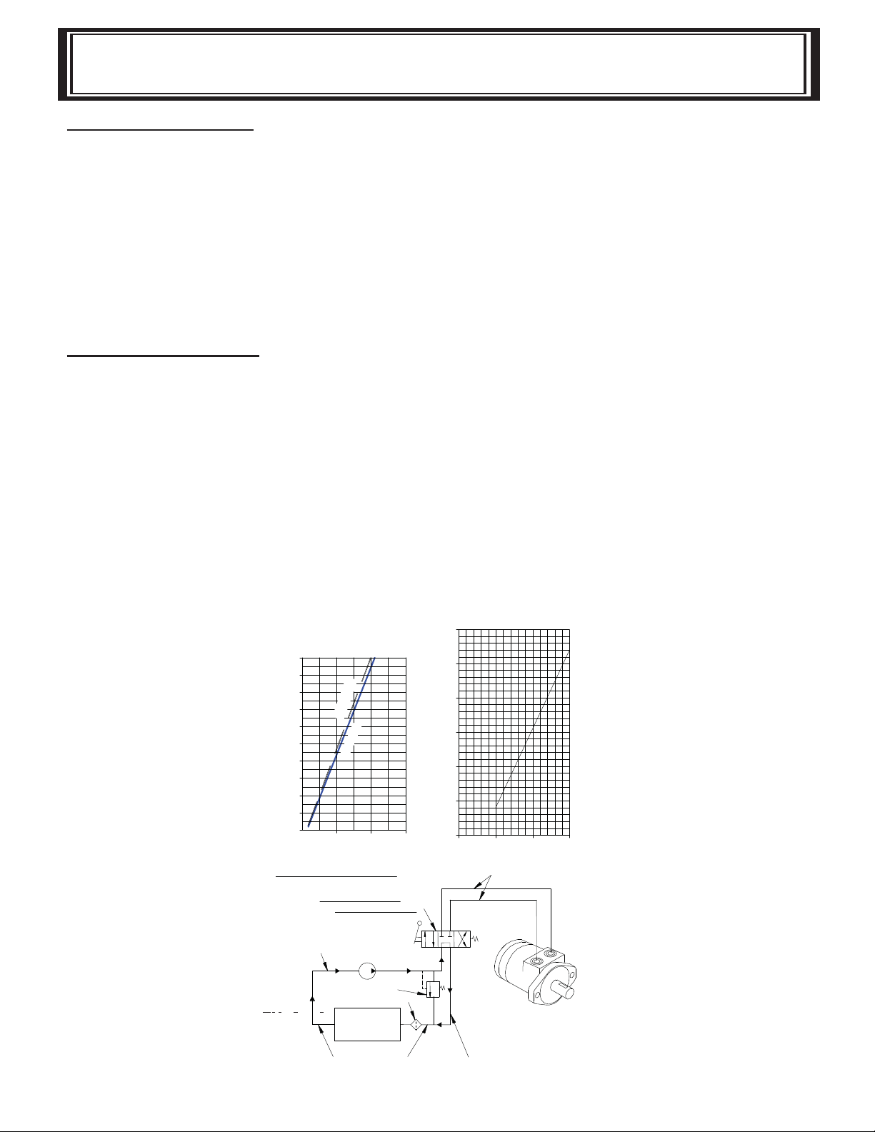
HYDRAULIC SYSTEMS
Refer to performance charts, below, to properly match your hydraulic system to the HDG-350
winch performance. The charts consist of:
1. Line pull (lbs.) first layer vs. working pressure (P.S.I.). STATIC refers to lifting a suspended
load from rest; DYNAMIC refers to maintaining the motion of a moving load.
2. Line speed, first layer (F.P.M.) vs. gallons per minute (G.P.M.).
Performance based on a motor displacement of 3.6 cubic inches with 15 GPM maximum flow
rate.
HSW-10,000 PERFORMANCE
10,000 LB. DUTY RATING
30:1 GEAR RATIO
WITH 3.6 C.I.D. MOTOR
10,000
9,000
8,000
7,000
6,000
5,000
4,000
3,000
LINE PULL-FIRST LAYER (LB.)
2,000
1,000
0
DYNAMIC
STATIC
0
1,000
WORKING PRESSURE, PSI
TYPICAL LAYOUT
CONTROL VALVE
EMERGENCY STOP
3 POSITION 4 WAY
CYLINDER SPOOL
PUMP INLET LINE
(SUCTION)
PUMP
RELIEF VALVE
FLUID FILTER
FLUID
RESERVOIR
35
30
25
20
15
LINE SPEED-FIRST LAYER (FPM)
10
3,0002,000
5
0
5
FLOW (GPM)
HIGH PRESSURE LINES
(.50 I.D. MINIMUM)
WINCH MOTOR
15
10
HYDRAULIC
LOW PRESSURE LINES
LOW PRESSURE LINES
(.75 I.D. MINIMUM)
4
Page 7

TROUBLE SHOOTING GUIDE
CONDITION POSSIBLE CAUSE CORRECTION
Clutch inoperative 1. Dry or rusted shaft. 1. Clean and lubricate.
or binds up. 2. Bent yoke or linkage. 2. Replace yoke or shaft
assembly
3. Clutch jaws are in contact. 3. See Techniques of Operation
Oil leaks from 1. Seal damaged or worn. 1. Replace seal.
housing 2. Too much oil. 2. Drain excess oil. Refer to
Techniques of Operation.
3. Damaged gasket. 3. Replace gasket.
Winch runs too slow 1. Hydraulic motor worn out. 1 . Replace motor.
2. Low flow rate. 2. Check flow rate. Refer to
Hydraulic Systems flow
chart, page 4.
Cable Birdnests when 1. Drag brake disc worn. 1. Replace discs.
clutch is disengaged.
Hydraulic fluid leaks 1. Hydraulic motor shaft seal 1. Replace seal.
out hole in motor damaged.
adapter.
5
Page 8

INSTRUCTIONS FOR OVERHAUL
HSW10,000
1. Drain oil from gear housing by removing plug
(item #38) from bottom of gear housing. Remove
plugs (items #35 & # 37) from top of gear hous ing. Remove handle (item #10) by driving pin
(item #39) from shifter shaft of winch. Remove
angles (items #3 & #4) from winch by removing
hardware shown.
2. Remove clutch housing (item # 12) and clutch
(item #5) from winch assembly.
Remove two keys (item #32) from keyways. A
screwdriver can be used, at notch, to aid in the
removal of key. Once keys have been removed,
drum (item #8) and thrust washer (item #47) can
be removed from drum shaft.
DIS-ASSEMBLY
3. Remove motor (item #36) and coupling (item
#6) from adapter (item #2) by unscrewing two
capscrews (item #24) with lockwasher (item
#28).
Remove keys (item #13) from worm shaft. Un screw four capscrews (item #23) and remove
adapter (item #2) from gear housing. Replace
adapter seal (item #42) and gasket (item #30).
4. See page 12 for servicing the oil cooled brake.
Remove brake housing mounting screws (item #22)
and remove brake with gasket. Replace gasket
(item #30). Remove worm (item #15) and bear ings (item #16) from gear housing. Use soft ham mer to gently tap input end of worm and drive worm
and bearing from gear housing. Once worm has
been removed from housing, bearing can be
pressed from end of worm.
Check for signs of wear or damage to worm (item
#15) and bearing(item #16). Replace if necessary.
6
Page 9

5. Remove gear housing cover (item #7) from
gear housing (item #11) by unscrewing cap screws (item #19). Thread two of the cap screws into the two tapped holes of cover
and tighten. This will pull the cover loose
from gear housing.
Remove cover gasket (item #31) and pull
shaft (item #14), with gear attached, and
thrust washer (item #47) from gear housing.
6. Check for signs of wear on gear teeth. If re placement of gear is necessary, replace as
fol lows:
a. Press gear (item #9) from shaft (item #14).
b. Examine shaft keys and keyways. If dis-
tor tion of keys and/or keyways is evident,
shaft and keys should be replaced.
c. Use a soft hammer to gently tap keys (item
#33) into keyways. Press gear (item #9)
over shaft and keys. Gear must be cen tered over keys.
7. Remove seal (item #43) from back of gear
housing (item #11). Press bushing (item
#18) from gear housing. Press new bushing
and seal back into place.
8. Check drum bushings (item #17) for signs of
wear. Replace if necessary by pressing old
bushings from drum. Press new ones into
place.
7
Page 10

9. Examine shifter assembly (item #1) for
damage to yoke. Yoke should be fi rmly
attached to shaft, yet able to swivel freely
around shaft. Replace if necessary.
Install new shifter assembly (item #1) by
placing end of shaft, opposite yoke,
through spring (item #45) and into hous ing (item#12).
10. Check cover bushing (item #17) for
signs of wear. If necessary remove old
bushing and press bushing into place.
11. Apply grease to end of shaft, opposite
ge ar. Apply grease to bushing in gear
housing (item #11). Place greased end of
shaft through thrust washer (item #47) and
bushing in gear housing (item #11). Place
gasket (item #31) onto gear housing cover
(item #7). Apply grease to gear end of
shaft and cover bushing. Place cover onto
shaft and secure to housing with ten cap screws (item #19). Tighten capscrews to
8 ft. lbs. (10.8 Nm) each.
12. Press bearing (item #16) onto worm
(item #15). NOTE: Be sure that thick
shoulder of bearings outer race (side
with manufacturer’s name and part
number) is out, away from worm
threads. Press bearing and worm into
gear housing. Slip new gasket (item
#30) onto brake housing. Use four cap screws (item #22) to secure brake hous ing to gear housing. TIGHTEN
CAPSCREWS TO 8 FT. LBS. (10.8
Nm.) EACH. See re-assembling
and checking the brake on page 13
to complete brake assembly.
8
Page 11

13. Press bearing (item #16) onto worm and
into housing. NOTE: Be sure that thick
shoulder of bearings outer race (side with
manufacturer’s name and part number) is
out, away from worm threads. Place
gasket (item #30) onto adapter (item #2).
Attach adapter to gear housing using
four (4) capscrews (item #23).
TIGHTEN CAPSCREWS TO 12 FT. LBS.
(16.3 Nm.) EACH.
Insert keys (item #13) into keyways of
worm shaft. Slide tapered end of cou pling (item #6) over end of worm shaft.
Be sure roll pin (item #39) is in coupling.
Place motor shaft, with key in keyway,
into coupling. Secure motor to adapt er, using two (2) capscrews (item #24)
and lockwashers (item #28).
TIGHTEN CAPSCREWS TO 75 FT.
LBS. (102 Nm.) EACH.
14. Place winch with gear housing cover
down on work bench. Drum shaft
should be in vertical position. Slide
thrust washer (item #46) over drum
shaft and slide downward until washer
rests on gear housing. Set springs
(item #44) into pockets of gear hous ing with drag brakes (item #29) on top
of springs. Slide drum assembly (item
#8) onto drum shaft with drum jaws
upward.
9
Page 12

15. Place thrust washer (item #47) over end
of drum shaft and slide downward until
spacer rests on drum. Press drum down ward to compress springs in gear hous ing.
Insert keys (item #32) into keyways with
sharp edge of keys pointing outward and
notched end of keys upward. A rubber or
brass mallet will be needed to gently tap
keys into position.
Apply grease to keys and end of shaft.
Place jaw clutch (item #5) over end of
shaft and slide jaw clutch over keys.
Set clutch housing (item #12) over end of
drum shaft. Pull jaw clutch (item #5) up ward, to ward clutch housing, enough to
allow yoke, in clutch housing, to fi t prop-
erly in groove around jaw clutch.
16. Attach angles (item #3 & #4) using six
capscrews (item #21) with lockwashers
(item #27) and two capscrews (item #20)
with lockwasher (item #27). Torque cap-
screws to 34 ft. lbs. (46 Nm.) each. Insert
plug (item #38) into bottom of gear hous ing. Permatex may be applied to threads
to help prevent leakage.
Attach handle (item #10) to clutch shaft
using pin (item #39).
Pour 1 pint of SAE 140 EP gear oil into
housing through hole in top of housing.
Insert relief fi tting (item # 35) into reducer
(item #37). Reducer should then be placed
into hole on top of gear housing. Tighten
fi tting and reducer securely.
10
Page 13

ADJUSTING THE OIL COOLED WORM BRAKE
The oil-cooled, fully adjustable, automatic brake operates in the worm housing lubricant, all parts
being submerged in oil. When the brake wears to the point that the load begins to drift, the brake
can be adjusted as follows:
1. Loosen the lock nut on the adjusting screw.
2. Tighten the brake by turning the adjusting screw clockwise. CAUTION: Only ¼ turn is usu ally required to adjust the brake. Over-tightening can cause overheating, and damage to the
brake parts. Tighten the lock nut after adjustment is completed.
If the brake does not respond to adjustment then a new leaf spring and brake disc is
needed.
A torque wrench can be equipped with a special adapter to fi t the input shaft (worm) of the winch.
The adapter can be made by welding a nut to the end of a piece of tubing as shown below.
After welding the cap and nut to the tubing, slot the tubing as shown. This will allow the special
adapter to slide over the keyway and will then act as a large socket. A torque wrench can then be
used to apply the proper torque. Turn the torque wrench so that the drum turns in the spool out
direction or lowering direction. The torque rating for the Model HSW 10,000 should be 9 to 15 ft.
lbs. If the torque wrench does not show the proper value as it turns, then the worm brake adjusting bolt should be turned clockwise ¼ turn to increase the torque setting. Each time the adjusting
bolt is turned, check the torque reading. Continue this procedure until the proper torque reading is
achieved. Then tighten the lock nut.
11
Page 14

SERVICING THE OIL COOLED BRAKE
SERVICING OF THE OIL COOLED BRAKE
1. Back off the lock nut, then the adjusting screw, both two turns or
more by turning them counter-clockwise.
2. Remove the cover mounting screws.
3. Remove the cover along with coil spring and leaf spring.
4. Remove the retainer plate, composition brake disc, cam plate
and balls.
5. Inspect parts as follows:
a. Composition brake discs are 1/8” thick when new. Replace if thinner
than 0.080” or if surfaces are glazed or burnt.
b. Inspect the fl at, ground surface of the cam plate and retainer plate for
glazing, warpage, or other damage. Glazing can be removed by scraping carefully.
c. Inspect the leaf spring. It should be bowed 1/8”.
12
Page 15

RE-ASSEMBLY & TESTING BRAKE
RE-ASSEMBLING AND CHECKING THE BRAKE
1. Press brake hub into place over worm shaft and key.
2. Assemble balls into appropriate slots of cam. Use stiff grease to hold balls into place
and slide cam over end of worm. Be sure that balls are secure, between cam slots
and hub slots. Refer to Diagram 1 on page 12.
3. Install brake disc.
4. Install retainer plate, smooth side toward brake disc.
5. Install the gasket on the cover with a small amount of grease or sealer
6. The coil spring goes over the adjusting screw on the inside of the cover.
7. Install the notches of the leaf spring on the pins protruding through the cover. The
hollow side of the leaf spring goes toward the brake.
8. Install brake housing cover, making sure the protruding pins go through the leaf
spring and into the holes on the retainer plate. Tighten capscrews to 7-8 ft. lbs.
9. Bolt cover into place with the mounting screws. Install drain plug and add 1 pint of
SAE 140 EP oil.
10. Turn winch in the reel in direction at least one turn of the input shaft.
11. Turn the adjusting screw in until it is fi nger tight.
TEST FOR PROPER BRAKE ASSEMBLY
After the brake has been adjusted to the proper torque setting (See page 11), disengage clutch.
Start vehicle engine and run winch in the reel in direction. Allow winch to run in this direction for
one minute.
Place your hand on the brake housing. If housing is not hot to the touch then run winch in the
reverse direction (cable out) for one minute. Brake housing should begin to heat.
When these conditions exist, proper installation has been made. If heating becomes noticeable
when running the winch in forward rotation (reel in direction) the brake should be disassembled.
When disassembled, place the brake balls in the alternate set of slots in the cam plate, then carefully follow the instructions for reassembling and checking the brake.
13
Page 16

36.00
914,4
8.94
227,0
.
6
9
17.
5
2.50
6
3,5
13.12
333,3
2.50
6
3,5
1.3
7
3
4,9
3
.
5
0
88,9
7
.
2
5
184
,
2
11.
3
1
287,3
4.56
115,8
2.06
5
2,3
6.22
1
58,0
3.72
94,5
CLUTCH AT
DIS-ENGAGED
POSITION
.
5
0
12,7
2.5
0
6
3,5
2.50
6
3,5
.
5
0
12,7
7
.78
197,6
FL
ANGE
BARREL
DIMENSIONS SHOWN
ARE INCHES OVER MIL
LIMETERS.
12.25
311,1
6.35
161,3
3.62
92,
0
2.12
5
4,0
2.12
53,
8
5.75
1
46,1
HSW 10,000 DIMENSIONAL
MODEL HSW 10,000 RAM-LOK
14
Page 17

BRAKE DRAWING
AND PARTS LIST
ITEM NO QTY PART NO. DESCRIPTION
101 1 306034 SPRING-FLAT
102 1 314008 CAM PLATE
103 1 328128 COVER-WM BRK
104 1 338007 BRA KE HOUSI NG
105 1 340082 HU B
106 1 352022 RETAINER PLATE
107 2 400003 BALL
108 2 414021 BOLT-1/4NCX1,HX D,G8,A LLTHD,HV/P,Z/P
109 4 414039 CAPSCREW-1/4-20NC X 1 LG,H EXHD,GR 5
110 1 414224 BOLT-3/8-16NCX 1 1/2,H X,G5,AL-TH,Z/P
111 1 418036 NU T-3/8-16 NC,HEX JAM
112 2 418154 WASHER-1/4 FLAT ALUM.
113 1 442189 GASKET
114 1 474001 PLATE THRUST
115 1 486069 THREAD SEAL
116 4 486070 THREAD SEAL
117 1 494007 SPRING
15
Page 18

HSW 10,000
EXPLODED VIEW
SEE PAGE 15 FOR
BRAKE ASSEMBL Y
22
PARTS BREAKDOWN
48
31
38
7
19
27
21
30
13
35
29
27
20
32
4
8
44
33
14
32
17
37
33
16
46
29
15
43
18
44
9
11
30
2
6
36
47
38
16
42
17
39
23
28
24
40
25
34
41
39
45
10
26
1
17
47
5
3
17
12
27
20
27
21
16
Page 19

HSW 10,000
PARTS LIST
ITEM QTY PART DESCRIPTION ITEM QTY PART DESCRIPTION
1 1 276056 SHIFTER ASSEMBLY 25 1 416030 SETSCREW 1/4-20NC X 3/8 HX SOC
11 1 338273 HOUSING-GEAR 35 1 456008 FITTING-RELIEF
10 1 336010 HANDLE 34 1 456001 FITTING-LUBE
17
13 3 342027 KEY 37 1 468002 REDUCER
12 1 338308 HOUSING-CLUTCH 36 1 458111 MOTOR
14 1 357487 SHAFT-DRUM "STD" 38 2 468011 PIPE PLUG
15 1 368202 WORM-R.H. 30:1 39 2 470033 SPIRAL PIN
17 4 412003 BUSHING 41 1 472013 PLASTIC SEAL
16 2 402002 BEARING-BALL 40 1 472012 PLUG-RUBBER
19 10 414045 CAPSCREW 1/4-20NC X 7/8 LG HXHD G R 5 43 1 486017 OIL SEAL
18 1 412097 BUSHING 42 1 486009 OIL SEAL
20 2 414275 CAPSCREW 3/8-16NC X 7/8 LG HXHD GR 5 44 2 494002 SPRING
21 6 414282 CAPSCREW 3/8-16NC X 1-1/4 LG HXHD GR 5 45 1 494053 SPRING
22 4 414021 CAPSCREW 1/4-20UNC X 1 LG, NYLON PATCH, GR 8 46 1 518014 THRUST WASHER
24 2 414952 CAPSCREW 1/2-13NC X 1-1/2 LG SOCHD Z/P 48 4 486069 SEAL
23 4 414842 CAPSCREW 1/4-20NC X 1-3/4 LG SOCHD L/W 47 2 518015 THRUST WASHER
9 1 334179 GEAR-R.H. 30:1 33 4 450016 KEY-BARTH
8 1 332105 DRUM 32 2 450006 KEY-BARTH
7 1 328134 COVER 31 1 442205 GASKET
6 1 324500 COUPLING 30 2 442184 GASKET
5 1 324160 JAW CLUTCH 29 2 330010 DISC-BRAKE
4 1 303077 ANGLE 28 2 418218 LOCKWASHER 1/2 MED SECT
3 1 303076 ANGLE 27 8 418177 LOCKWASHER 3/8 MED SECT
2 1 300057 ADAPTER 26 1 416059 SETSCREW 3/8-16NC X 1/2 LG SOC HD
Page 20

LIMITED WARRANTY
RAMSEY WINCH warrants each new RAMSEY Winch to be free from defects in material and
workmanship for a period of one (1) year from date of purchase.
The obligation under this warranty, statutory or otherwise, is limited to the replacement or repair
at the Manufacturer’s factory, or at a point designated by the Manufacturer, of such part that
shall appear to the Manufacturer, upon inspection of such part, to have been defective in material or workmanship.
This warranty does not obligate RAMSEY WINCH to bear the cost of labor or transportation
charges in connection with the replacement or repair of defective parts, nor shall it
apply to a product upon which repair or alterations have been made, unless authorized by
Manufacturer, or for equipment misused, neglected or which has not been installed correctly.
RAMSEY WINCH shall in no event be liable for special or consequential damages. RAMSEY
WINCH makes no warranty in respect to accessories such as being subject to the warranties of
their respective manufacturers.
RAMSEY WINCH, whose policy is one of continuous improvement, reserves the right to im-
prove its products through changes in design or materials as it may deem desirable without being obligated to incorporate such changes in products of prior manufacture.
If fi eld service at the request of the Buyer is rendered and the fault is found not to be with
RAMSEY WINCH’s product, the Buyer shall pay the time and expense to the fi eld representa-
tive. Bills for service, labor or other expenses that have been incurred by the Buyer without approval or authorization by RAMSEY WINCH will not be accepted
RAMSEY WINCH COMPANY
Post Offi ce Box 581510
Tulsa, Oklahoma 74158-1510
Telephone: (918) 438-2760
FAX: (918) 438-6688
OM-914262-1113-A
 Loading...