

Page 1
OPERATING, SERVICE AND
MAINTENANCE MANUAL
MODEL HD-P10000
PLANETARY WINCH
CAUTION: READ AND UNDERSTAND THIS MANUAL BEFORE INSTALLATION AND
OPERATION OF WINCH. SEE WARNINGS!
Page 2

TABLE OF CONTENTS
INTRODUCTIONS . . . . . . . . . . . . . . . . . . . . . . . . . . . . . . . . . . . . . . . . . . . . . . . . . . . . . . . . . . . . . . . .1
WARRANTY INFORMATION . . . . . . . . . . . . . . . . . . . . . . . . . . . . . . . . . . . . . . . . . . . . . . . . . . . . . . . .1
SPECIFICATIONS . . . . . . . . . . . . . . . . . . . . . . . . . . . . . . . . . . . . . . . . . . . . . . . . . . . . . . . . . . . . . . . .1
WARNINGS . . . . . . . . . . . . . . . . . . . . . . . . . . . . . . . . . . . . . . . . . . . . . . . . . . . . . . . . . . . . . . . . . . . .1
WINCH MOUNTING . . . . . . . . . . . . . . . . . . . . . . . . . . . . . . . . . . . . . . . . . . . . . . . . . . . . . . . . . . . . . .2
CABLE INSTALLATION . . . . . . . . . . . . . . . . . . . . . . . . . . . . . . . . . . . . . . . . . . . . . . . . . . . . . . . . . . . .3
HYDRAULIC SYSTEM REQUIREMENTS . . . . . . . . . . . . . . . . . . . . . . . . . . . . . . . . . . . . . . . . . . . . . . .4
TYPICAL LAYOUT . . . . . . . . . . . . . . . . . . . . . . . . . . . . . . . . . . . . . . . . . . . . . . . . . . . . . . . . . . . . . . .4
PERFORMANCE CHARTS . . . . . . . . . . . . . . . . . . . . . . . . . . . . . . . . . . . . . . . . . . . . . . . . . . . . . . . . .4
OPERATION . . . . . . . . . . . . . . . . . . . . . . . . . . . . . . . . . . . . . . . . . . . . . . . . . . . . . . . . . . . . . . . . . . . .5
MAINTENANCE . . . . . . . . . . . . . . . . . . . . . . . . . . . . . . . . . . . . . . . . . . . . . . . . . . . . . . . . . . . . . . . . .5
TROUBLE SHOOTING GUIDE . . . . . . . . . . . . . . . . . . . . . . . . . . . . . . . . . . . . . . . . . . . . . . . . . . . . . . .6
OVERHAUL INSTRUCTIONS . . . . . . . . . . . . . . . . . . . . . . . . . . . . . . . . . . . . . . . . . . . . . . . . . . . . .7-12
DIMENSIONAL DRAWINGS . . . . . . . . . . . . . . . . . . . . . . . . . . . . . . . . . . . . . . . . . . . . . . . . . . . . .14-15
PARTS LIST AND PARTS DRAWINGS . . . . . . . . . . . . . . . . . . . . . . . . . . . . . . . . . . . . . . . . . . . . .16-19
LIMITED WARRANTY . . . . . . . . . . . . . . . . . . . . . . . . . . . . . . . . . . . . . . . . . . . . . . . . . . .BACK COVER
Page 3
PLEASE READ THIS MANUAL CAREFULLY
This manual contains useful ideas for obtaining the most efficient operation from your Ramsey Winch, and safety procedures
one needs to know before operating a Ramsey Winch. Do not operate this winch until you have carefully read and understand
the "WARNING" and "OPERATION" sections of this manual.
WARRANTY INFORMATION
Ramsey Winches are designed and built to exacting specifications. Great care and skill go into every winch we make. If the
need should arise, warranty procedure is outlined on the back of your self-addressed postage paid warranty card. Please read
and fill out the enclosed warranty card and send it to Ramsey Winch Company. If you have any problems with your winch,
please follow instructions for prompt service on all warranty claims. Refer to back page for limited warranty.
SPECIFICATIONS*
NOTE: The rated line pulls shown are for the winch only. Consult the wire rope manufacturer for wire rope ratings.
WARNINGS:
A MOTOR SPOOL (OPEN CENTER) DIRECTIONAL CONTROL VALVE IS REQUIRED FOR BRAKE OPERATION.
CLUTCH MUST BE FULLY ENGAGED BEFORE STARTING THE WINCH.
DO NOT DISENGAGE CLUTCH UNDER LOAD.
DO NOT LEAVE CLUTCH ENGAGED WHEN WINCH IS NOT IN USE.
STAY OUT FROM UNDER AND AWAY FROM RAISED LOADS.
STAND CLEAR OF CABLE WHILE PULLING. DO NOT TRY TO GUIDE CABLE.
DO NOT EXCEED MAXIMUM LINE PULL RATINGS SHOWN IN TABLE.
DO NOT USE WINCH TO LIFT, SUPPORT, OR OTHERWISE TRANSPORT PERSONNEL.
A MINIMUM OF 5 WRAPS OF CABLE AROUND THE DRUM BARREL IS NECESSARY TO HOLD THE LOAD. CABLE CLAMP
(SETSCREW) IS NOT DESIGNED TO HOLD LOAD.
IN CAR CARRIER APPLICATIONS, AFTER PULLING VEHICLE ON CARRIER, BE SURE TO SECURE VEHICLE TO CARRIER
BED. DO NOT MAINTAIN LOAD ON WINCH CABLE WHILE TRANSPORTING VEHICLE. DO NOT USE WINCH AS A TIEDOWN.
WHEN PULLING A HEAVY LOAD PLACE A BLANKET, JACKET, OR TARPAULIN OVER THE CABLE FIVE OR SIX FEET FROM
THE HOOK.
AVOID CONDITIONS WHERE LOAD SHIFTS OR JERKS OCCUR, AS THEY MAY INDICATE A DANGEROUS SITUATION.
1
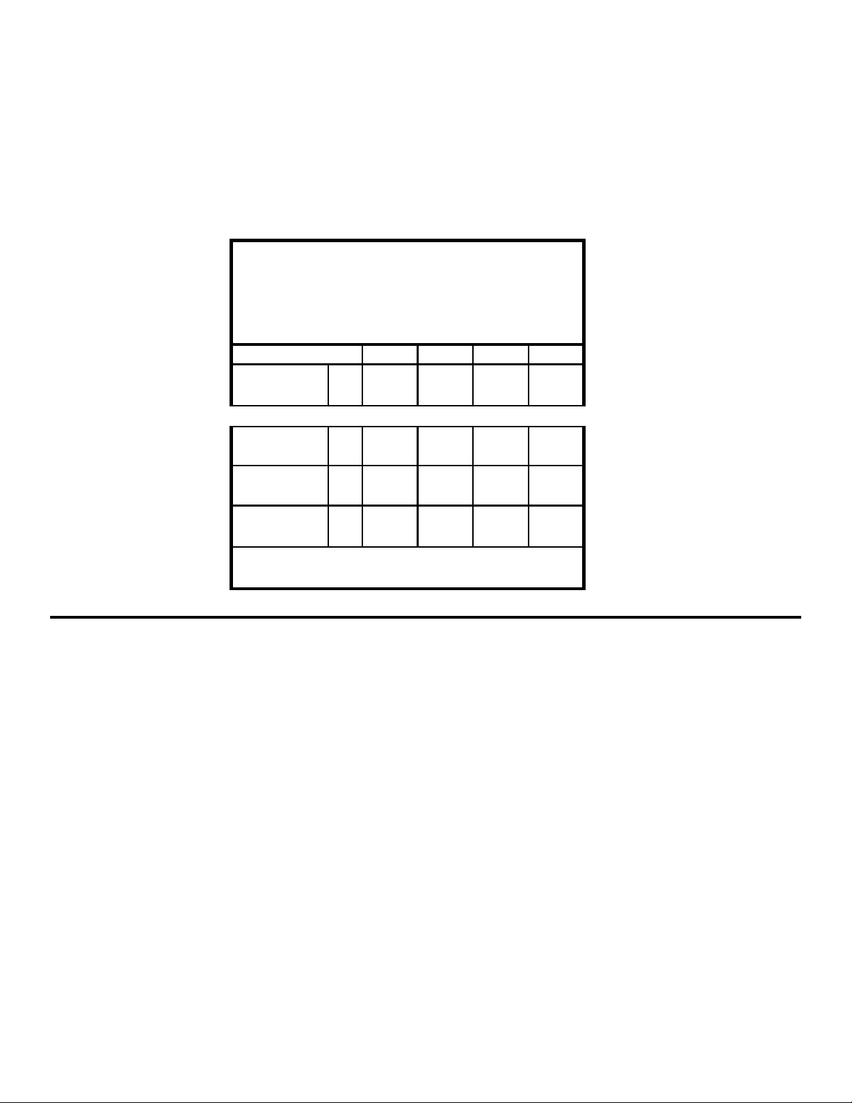
Rated Line P ul l (lbs.)
………………………………………
10,000
(Kg.)
………………………………………
4,530
Gear Reduct i on 5.1: 1
HD-P10000 STD 87 lbs . (39. 5 Kg)
HD-P10000 "Y " 82 lbs . (37. 2 Kg)
1234
lbs. 10,000 8,300 7,100 6200
Kg. 4,530 3,760 3,220 2810
ft.205080115
m 6 15 24 35
ft.15305575
m491622
FPM32384451
MPM 9.8 11.6 13.4 15.5
……………………………………………..
Wei ght (wit hout cable)
* These specificat i ons are based on rec om m ended wire rope of
7/16" (11m m ) E IPS c abl e and a 24. 9 cu. i n./Rev. mot or.
LAYER OF CABLE
*Rated li ne pul l
per layer
HD-P10000
(STD. DRUM )
* Line S peed (at
15 GPM )
HD-P10000 ("Y "
DRUM)
* Cable Capaci ty per Lay er
Page 4
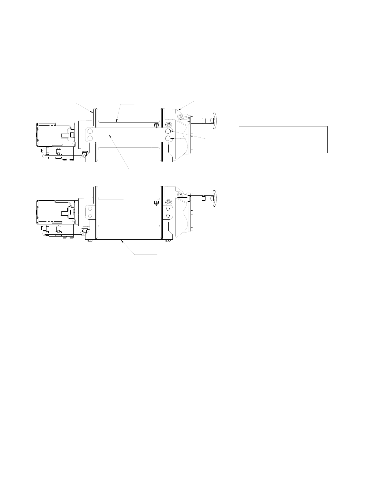
WINCH MOUNTING
ESSENTIAL MOUNTING INSTRUCTIONS TO MAINTAIN ALIGNMENT OF PLANETARY WINCH COMPONENTS:
It is most important that this winch be mounted securely so that the three major sections (the motor end, the cable
drum, and the gear housing end) are properly aligned. Excessive bushing wear and difficulty in freespooling are usually symptoms of misalignment.
In the as-installed condition, if the winch is mid-mounted, then at least one tie-plate must be attached to the mounting
feet at the bottom of the winch to maintain alignment. If the winch is foot mounted then at least one tie-plate must
remain mounted at midpoint of winch to maintain alignment. It is always preferred to used BOTH tie-plates in the final
installed configuration.
Angle Mounting Kit, P/N 251006 (for Std. Drum) or 251007 (for “Y” drum), is recommended for maximum ease in
mounting the winch. The angle kit will allow the winch to be mounted in upright or midmount applications and will
meet the criteria of serving as a solid and true mounting surface.
When mounting the winch with other than the recommended Ramsey Angle Kit, the mounting hole patterns described
in the Dimensional drawings on pages 14-15 should be used. The mounting surface must be flat within .015 inch
and sufficiently stiff to resist flexing. If a steel plate is used for foot mounting, it should be .750 inch thick. For this
mounting application eight (8) 1/2-13NC x 1-1/2” long grade 5 capscrews with lockwashers will be needed to mount
winch. Capscrews should be tightened to 55 ft-lb (75 Nm) torque.
NOTE: If angles or a steel plate are used in mounting winch, tie-plates provided with winch are to be attached to the
remaining mounting pads, whether they be side or foot.
* CAUTION: If longer bolts (minimum grade 5) are substituted to mount winch or to mount a roller guide at the
side mount pads, bolt length must be such as to allow a minimum of .50 inch thread length engagement in the
tapped holes in side of each end bearing. Refer to pages 14-15. Use of excessive length bolts will damage the
winch and prevent freespool of the drum. Torque bolts to 55 ft-lbs. (75 Nm).
2
MID MOUNT
FOOT MOUNT
SEE BOLT LENGTH
CAUTION BELOW *
TIEPLATE AT FOOT (BASE) LOCATION
TIEPLATE AT SIDE LOCATION
GEAR HOUSING END
CABLE DRUMMOTOR END
Page 5
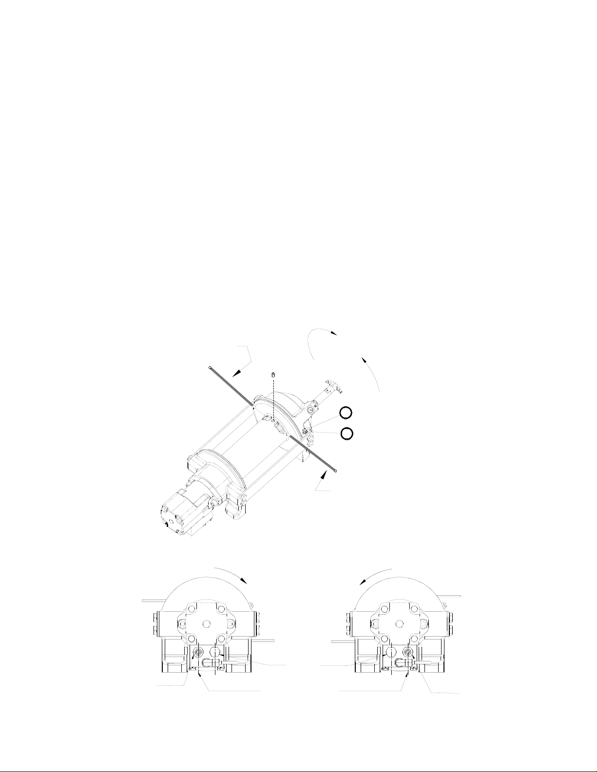
CABLE INSTALLATION
An “A” or “B” decal on the clutch end bearing indicates the spooling direction of the cable. Also, a letter “A” or “B” is
stamped in the end bearing on the clutch end indicating rotation direction. If the decal is damaged or unreadable,
contact Customer Service for additional instructions to determine proper direction. To reverse the rotation direc-
tion, exchange positions of the cartridge and plug shown below.
1. Unwind cable by rolling it out along the ground to prevent kinking. Securely wrap end of cable, opposite hook,
with plastic or similar tape to prevent fraying.
2. Place taped end of cable into hole in cable drum as shown below. Use the 3/8-16NC x 1/2” long hex socket
drive setscrew (included with drum assembly item #1) to secure cable to drum.
3. Carefully run winch in the "reel-in" direction. Keeping tension on end of cable, spool all the cable onto the cable
drum, taking care to form neatly wrapped layers.
After installing cable, check freespool operation. Disengage clutch and pull on cable at a walking speed. If cable
“birdnests”, loosen jam nut (item #20) and turn nylon setscrew (item #17) clockwise to increase drag on drum. If
cable pull is excessive, loosen nylon setscrew by turning counterclockwise. Tighten jam nut when proper setting is
obtained. CAUTION: OVER-TIGHTENING OF JAM NUT MAY STRIP NYLON SETSCREW.
3
INSERT CABLE AS SHOWN FOR "A" ROTATION
OVERWOUND APPLICATION.
(UNDERWOUND APPLICATION REQUIRES CABLE TO
COME UNDER DRUM FROM OPPOSITE DI RE CTION
AND INSERTED IN THIS SAME CABLE POCKET.)
INSERT CABLE AS SHOWN FOR "B" ROTATION
OVERWOUND APPLICATION.
(UNDERWOUND APPLICATION REQUIRES CABLE TO
COME UNDER DRUM FROM OPPOSITE DI RE CTION
AND INSERTED IN THIS SAME CABLE POCKET.)
"B" ROTATION
DIRECTION
"A" ROTATION
DIRECTION
SETSCREW
17
20
PLUG
POSITION
CARTRIDGE
POSITION
CARTRIDGE
POSITION
CABLE DRUM
ROTATION DIRECTION
CABLE DRUM
ROTATION DIRECTION
"B" ROTATION
"A" ROTATION
(REEL IN) RAISE INLET
Page 6
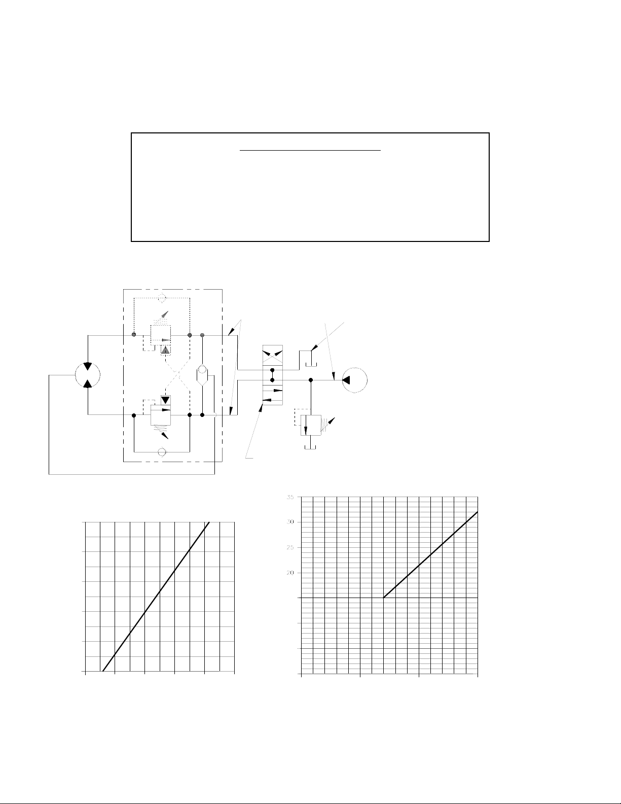
HYDRAULIC SYSTEM REQUIREMENTS
Refer to the performance charts below to properly match your hydraulic system to the winch performance. The
charts consist of:
(1) Line Pull first layer (lb.) vs. Working Pressure (PSI)
(2) Line Speed, first layer (FPM) vs. flow (GPM)
SYSTEM REQUIREMENTS
MOTOR SPOOL (OPEN CENTER) CONTROL VALVE REQUIRED
2100 PSI RELIEF VALVE SETTING
15 GPM FLOW RATE
DO NOT EXCEED 20 GPM--MOTOR AND WINCH MAY BE DAMAGED
10 MICRON NOMINAL FILTRATION
B
TYPICAL LAYOUT
WITH BRAKE RELEASE SHUTTLE
MOTOR
BRAKE
PORT
A
SYSTEM
RELIEF
3 POSITION
4 WAY VALVE
(MOTOR SPOOL)
MAX. FLOW &
PRESSURE AT
RATED LOAD:
15 GPM
2500 PSI
HIGH PRESSURE LINE
(.50 I.D. MINIMUM)
LOW PRESSURE LINE
(.75 I.D. MINIMUM)
PUMP
PORT CONTROL
(DUAL CART.
VALVE OPTION)
4
WORKING PRESSURE (PSI) AT 15 GPM
FLOW (GPM)
LINE PULL-FIRST LAYER (LB)
LINE SPEED-FIRST LAYER (FPM)
0 5 10 15
0
5
10
15
0
0
1000
2000
3000
4000
5000
6000
7000
8000
1000 2000 2500
BASED ON 24.9 CU. IN. MOTOR
1500500
PERFORMANCE CHARTS
9000
10000
NOTE: Dual counterbalance valve version at Maximum Flow will require an increased working pressure of 150 PSI.
Page 7

OPERATION
The best way to get acquainted with how your winch operates is to make test runs before you actually use it. Plan
your test in advance. Remember, you hear your winch as well as see it operate. Get to recognize the sounds of a light
steady pull, a heavy pull, and sounds caused by load jerking or shifting. Avoid conditions where load shifts or jerks
occur, as they may indicate a dangerous situation.
The uneven spooling of cable, while pulling the load, is not a problem, unless there is a cable pileup on one end of
the drum. If this happens, reverse the winch to relieve the load, and move your anchor point further to the center of
the vehicle. After the job is done you can unspool and rewind for a neat lay of the cable.
When pulling a heavy load, place a blanket, jacket, and tarpaulin over the cable about five or six feet behind the hook.
In the event of a broken cable, this will slow the snap back of the cable and could prevent serious injury.
The winch clutch allows rapid unspooling of the cable, from the cable drum, for hooking onto the load. The clutch is
operated by the clutch shifter lever or air shifter.
WARNING: DO NOT DISENGAGE CLUTCH UNDER LOAD!
MANUAL CLUTCH SHIFTER (Refer to dimensional drawing page 14):
TO DISENGAGE CLUTCH: Run the winch in the reverse (reel out) direction until the load is off the cable. Pull handle
out and rotate 90°. With handle in the “DISENGAGED” position, cable may now be free-spooled from the drum.
TO ENGAGE CLUTCH: Pull handle out, rotate 90° and release handle. Run the winch in reverse until the clutch handle
snaps fully into the “ENGAGED” position. DO NOT attempt to pull a load unless the handle is fully at the “ENGAGED”
position. If manual shift indicator light is present, the green light is lit when clutch is fully “ENGAGED”. DO NOT
attempt to pull a load unless the green light is lit. To install light to the vehicle electrical system refer to the Electrical
Schematic on page 15.
AIR CYLINDER CLUTCH SHIFTER (Refer to the dimensional drawing page 15):
TO DISENGAGE CLUTCH: Run the winch in the reverse (reel out) direction until load is off the cable. Apply air pres-
sure to the .125-27 NPT port: 80 PSI (min.)-150 PSI (max.). CAUTION: PRESSURE MUST NOT EXCEED 150 PSI.
TO ENGAGE CLUTCH: Remove air pressure from the cylinder (a return spring engages the plunger). Run winch in
reverse until the clutch engagement indicator light (green light) is lit. To install light to the vehicle electrical system
refer to the Electrical Schematic on page 15.
MAINTENANCE
1. Inspect the cable for damage and lubricate frequently. If the cable becomes frayed with broken strands, replace
immediately. Cable and hook assembly (100’ long cable) P/N 524118 (“Y” drum) or (150’ long cable) P/N
524119 (STD drum) may be purchased from a Ramsey distributor.
2. Check that the clutch is fully engaging. See OPERATION instructions, above, for the appropriate clutch shifter.
FOR MANUAL CLUTCH ONLY: Monthly, disengage clutch, put several drops of oil on the clutch handle shaft and
work clutch handle IN and OUT several times to lubricate inside the shifter assembly.
3. Check to see that the drum cable does not overrun (“birdnest”) when freespooling. Refer to page 3 if it does.
4. Replace drum bushings and seals if seals begin to seep grease. Refer to the Overhaul Instructions, pages 7-12.
Add additional lubricant, Mobilith SHC 007, to gears and drum bearings if required.
5
Page 8

TROUBLESHOOTING GUIDE
6
CONDITIONS POSSIBLE CAUSE CORRECTION/ACTION
DRUM WILL NOT ROTATE
AT NO LOAD
Winch not mounted squarely, causing end bearing
to bind up
Check mounting. Refer to Winch Mounting, page 2.
Gears damaged Inspect and replace damaged gears
DRUM WILL NOT ROTATE
UNDER LOAD
Winch not mounted squarely, causing end bearing
to bind up
Check mounting. Refer to Winch Mounting, page 2.
Load greater than rated capacity of winch Refer to Specifications page 1 for line pull rating.
Low hydraulic system pressure Check pressure. Refer to Hydraulic Systems per-
formance charts page 4.
WINCH RUNS TOO SLOW Low hydraulic system flow rate Check flow rate. Refer to Systerm Requirements and
Typical Layout page 4.
Motor worn out Replace motor
DRUM WILL NOT
FREESPOOL
Clutch not disengaged. Check Adjustment of Manual
Shifter, page 10.
Check Operation, page 5.
Winch not mounted squarely, causing end bearing
to bind up
Check mounting. Refer to Winch Mounting, page 2.
Side mounted bolts too long, causing binding of ring
gear (Item #15, page 16).
Check bolt length. Bolt thread MUST NOT engage
threaded holes in sides of end bearing more than the
.50 inch thread depth in the end bearing.
BRAKE WILL NOT HOLD Incorrect directional control valve (cylinder spool-
closed center)
Use only a motor spool (open center) control valve.
LOAD DRIFTS Excessive Backpressure (100 PSI Max.) Check for restrictions in hydraulic system. Refer to
System Requirements and Typical Layout page 4.
CABLE BIRDNESTS WHEN
CLUTCH IS DISENGAGED
Drag screw improperly adjusted Adjust nylon drag screw. Refer to Cable Installation,
page 3.
EXCESSIVE NOISE Hydraulic system flow too high Check flow rate. Refer to Typical Layout page 4.
Drum in bind, winch not mounted squarely Check mounting. Refer to Winch Mounting, page 2.
DRUM CHATTERS IN
“REEL IN” DIRECTION
Low hydraulic system flow rate Check flow rate. Refer to Typical Layout page 4.
Low hydraulic system relief pressure setting Check relief valve setting.
OIL LEAKS FROM
BREATHER VENT UNDER
MOTOR END BEARING
Damaged brake o-rings, backup rings, or sealing
surfaces
Disassemble brake and inspect. See Overhaul
Instructions, pg. 8.
Page 9

7
43
44
26
45
23
15
26
25
28
30
24
19
48
INSTRUCTIONS FOR OVERHAUL HD-P10000 SERIES WINCH
Take note of mounting configurations for proper mounting of parts during re-assembly. Replace all gaskets, o-rings, and seals during re-assembly.
Disconnect tube (item #44) from elbow fittings (items #26) on bottom of end bearing and counterbalance valve
(item #45). Remove motor (item #30) from end bearing by slowly unscrewing capscrews (items #18). CAUTION:
MOTOR IS UNDER SPRING PRESSURE.
Check breather vent (item #45). Make sure it is not clogged. If oil is leaking from vent, check brake o-rings, backup
rings, and sealing surfaces (see page 8).
Remove springs (items #43) from pockets and inspect for damage.
Replace gasket (item #28).
Remove coupling (item #25) from end bearing. Examine coupling for signs of wear, replace if necessary. If neces-
sary, remove counterbalance valve from motor by removing capscrews (items #15).
Page 10

Remove retaining rings (items #42 and 49) with screwdriver.
Remove brake parts from end bearing. NOTE POSITION OF O-RINGS AND BACKUP RINGS BEFORE REMOVAL.
Examine brake discs (items #5) and stators (items #4) for signs of wear, and replace if necessary.
Examine o-rings (items #31 and 32) and backup rings (items #34 and 36) in brake piston (item #6), as well
as o-ring (item #33) and backup ring (item #35) in backup brake piston (item #7) for signs of wear. Remove
o-rings and backup rings from grooves in brake piston or backup brake piston and replace if necessary.
42
34
32
49
7
6
5
31
36
33
35
4
8
Page 11

9
Remove tie plates (items #12) from end bearings by unscrewing capscrews (items #16). Slide motor end bearing
(item #10) and drum (item #1) from gear housing end bearing.
Remove input shaft (item #11) from end bearing. Inspect shaft and and output sun gear (item #8) for damage and
replace if necessary. To remove the output sun gear, remove the snap rings (items #41) and thrust washer (item
#47) and pull off the end of the shaft.
Remove bushing (item #14) and o-ring (item #37) from motor end bearing. Place new, well-oiled o-ring into groove
inside of end bearing and press new bushing onto end bearing.
14
37
10
41
47
8
11
1
12
16
12
16
Remove seal (item #40) from gear housing end bearing (item
#9). Loosen nut (item #22) and remove nylon setscrew (item
#18). Remove ring gear from gear housing end bearing, if necessary. Remove bushing (item #13) from end bearing.
Press new bushing into end bearing. Install ring gear, then
nylon setscrew and nut. Ring gear must be fully seated in end
bearing and slot in ring gear MUST NOT be aligned with clutch
shifter hole. Install new seal in end bearing, with sharp edge of
seal outward.
18
22
40
29
9
13
Page 12

10
Generously apply grease (MOBILITH SHC 007) to teeth of ring gear (item #29), teeth of planet gears in drum (item #1), and to
bushing (item #13) in gear housing end bearing. Apply a small amount of grease to base of bushing (item #14) on motor end
bearing. Apply grease to teeth of output sun gear (item #8) and input shaft (item #11).
Place end of shaft with output sun gear on it into drum. Rotate shaft to engage planet gears with output sun gear. Place Gear
End Bearing on Drum and engage planet gears with ring gear.
Assemble motor end bearing (item #10) to drum assembly and use tie plates (items #12) and capscrews (items #16) to hold
both end bearings together. Tighten capscrews to 55 ft-lbs (75 Nm).
If necessary, remove and replace the shifter assembly (manual, item #2, or air-cylinder, item #3), as follows:
MANUAL CLUTCH SHIFTER ASSEMBLY
Loosen setscrew (item #20) and jam nut on shifter assembly, then unscrew shifter assembly (item #2). Be sure slot in ring
gear is not aligned with clutch shifter hole. Rotate drum, if necessary, to ensure hole and slot are not aligned.
Reinstall shifter assembly with plunger, jam nut, and handle positioned in gear housing as shown below. Thread assembly (with
handle engaged in cylinder slot) into the gear housing. Pull drum toward the gear end bearing housing to remove play. Hold
drum in position and continue threading the shifter assembly in until the gap between the end of the handle and cylinder is
7/16
+0
-1/16
inch and handle is in the horizontal position (see below). Note: This gap will vary with drum endplay. With the
drum pulled against the motor end housing, the gap should be 3/8 inch.
Lightly tighten jam nut. Rotate drum until handle snaps fully into the engaged position. Pull handle out and rotate 90°. Verify that
drum can be rotated freely (at least one full revolution) with clutch shifter at the DISENGAGED position. Securely tighten jam nut
while holding the handle. Tighten setscrew (item #20) securely. Re-check clutch operation as described on page 5.
AIR CYLINDER SHIFTER ASSEMBLY
Loosen set screw (item #20) to remove shifter assembly (item #3). To reinstall, place 1 or 2 shims (items #44) over plunger
and thread shifter assembly into gear end housing. Add or remove shims to orient ports for pneumatic connections. Ports
should point down (below horizontal). Tighten setscrew. Check for clutch operation as described on page 5.
If the light assembly (item #2) or light switch (item #48) needs to be replaced, refer to the schematic on page 15 for electrical
connections and disassemble and reassemble as shown below.
JAM NUT
PLUNGER
AIR-CYLINDER
CLUTCH SHIFTER
MANUAL CLUTCH
SHIFTER
MANUAL CLUTCH ADJUSTMENT
HANDLE (HORIZONTAL)
CYLINDER
23
4
41
2
3
44
21
2
20
9
42
48
LIGHT SWITCH
LIGHT ASSEMBLY
Page 13

Set winch with gear housing end down on work surface.
Install well-oiled o-rings and backup rings into grooves on outside of brake piston and backup brake piston as shown
in cross-section A-A below.
Piston, backup piston, brake discs and stators must be clean and free of grease and oil.
Insert brake discs (item #5) and stators (item #4) into gear end alternating, with stators first and last.
Insert backup brake piston (item #7) into motor end and insert brake piston (item #6) into it. Apply even pressure
on piston when installing.
Install retaining rings (items #42 and 49) into grooves in motor end housing.
34
32
MOTOR SIDE
A
33 35
36
31
49
42
34
32
7
6
31
36
33
35
4
A
5
6
7
SECTION A-A
DRUM SIDE
11
Page 14

12
Insert springs (item #43) into pockets in back of brake piston.
Install roll pin (item #38) into new motor coupling below bottom of spline teeth. Insert motor coupling (item
#25), engaging it with the discs and the input shaft.
Place gasket (item #28) on mounting surface of motor (item #30). Slide motor shaft into coupling. Attach motor to
motor end bearing housing using (2) capscrews (item #19) and (2) lockwashers (item #24). Evenly tighten to 49 ftlbs. (66 Nm) torque.
Install the counterbalance valve (item #45) to the motor using (4) capscrews (item #15) and (4) lockwashers (item
#23). Tighten to 17 ft-lbs (23 Nm).
Securely connect fittings (item #26) to motor end housing and counterbalance valve, and connect tube assembly
(item #44) to fittings.
Apply at least 550 PSI hydraulic system pressure to brake and verify that brake releases (winch drum will rotate).
38
43
45
23
15
25
28
30
24
19
26
26
44
48
Page 15

13
NOTES
Page 16

14
BARREL
CLUTCH ENGAGED POSITION
CLUTCH DISENGAGED POSITION
1/2-13UNC X .75 (INCHES) DEEP TAPPED HOLE
(2-PLACES EACH SIDE OF MOTOR END BEARING)
7/8-14 SAE PORT
(2-PLACES)
(2-PLACES EACH SIDE OF GEAR HOUSING END BEARING)
1/2-13UNC X .50 (INCHES) DEEP TAPPED HOLE
NOTES:
1. DIMENSIONS SHOWN ARE INCHES OVER MILLIMETERS.
2. WINCH MOUNTING CAPSCREWS MUST MEET OR EXCEED SAE GRADE 5 SPECIFICATION.
3. THESE HOLE LOCATIONS MUST BE HELD WITHIN ±.03 (0.8mm)
OF TRUE POSITION. RECOMMENDED MOUNTING HOLE DIAMETER IS .53 (13.5mm).
FLANGE
*
1.25
[31.8]
7.17
[182.1]
Ø3.94
[100.0]
DRUM
C
L
(TYP)
1.12
[28.4]
*
(TYP)
(TYP)
1.12
[28.4]
*
*
4.68
[118.9]
9.36
[237.7]
MOVE TIE PLATES TO FEET
FOR SIDE MOUNT INSTALLATIONS,
8.38
[212.9]
1/2-13UNC X .75 (INCHES) DEEP TAPPED HOLE
(4-PLACES EACH END BEARING)
CABLE ANCHOR
*
*
B
4.92
[125.0]
9.41
[239.1]
3.79
[96.3]
F
Ø8.25
[209.6]
A
.50
[12.7]
D E
C
2.21
[56.1]
2.21
[56.1]
4.25
[108.0]
8.38
[212.7]
4.19
[106.4]
2.25
[57.2]
.56
[14.3]
Ø.50
[Ø12.7]
213,6
8.41
255,0
10.04
228,6
9.00
311,2
12.25
165,1
6.50
247,7
9.75
C
INCHES
MM
B
INCHES
MM
A
MM
INCHES
HD-P10000
HD-P10000
MODEL
WINCH
MM
INCHES
D
MM
INCHES
E
15.55
394,9
13.93
353,8
13.28
337,3
11.66
296,1
STD. DRUM
"Y" DRUM
649,9
25.59
732,5
28.84
F
INCHES
MM
HD-P10000 MANUAL SHIFT
Page 17

BARREL
1/2-13UNC X .75 (INCHES) DEEP TAPPED HOLE
(2-PLACES EACH SIDE OF MOTOR END BEARING)
7/8-14 SAE PORT
(2-PLACES)
(2-PLACES EACH SIDE OF GEAR HOUSING END BEARING)
1/2-13UNC X .50 (INCHES) DEEP TAPPED HOLE
NOTES:
1. DIMENSIONS SHOWN ARE INCHES OVER MILLIMETERS.
2. WINCH MOUNTING CAPSCREWS MUST MEET OR EXCEED SAE GRADE 5 SPECIFICATION.
3. THESE HOLE LOCATIONS MUST BE HELD WITHIN ±.03 (0.8mm)
OF TRUE POSITION. RECOMMENDED MOUNTING HOLE DIAMETER IS .53 (13.5mm).
FLANGE
1.25
[31.8]
Ø3.94
[100.0]
DRUM
C
L
(TYP)
1.12
[28.4]
1.12
[28.4]
4.68
[118.9]
9.36
[237.7]
MOVE TIE PLATES TO FEET
FOR SIDE MOUNT INSTALLATIONS,
1/2-13UNC X .75 (INCHES) DEEP TAPPED HOLE
(4-PLACES EACH END BEARING)
CABLE ANCHOR
2.21
[56.1]
12V BATTERY
INDICATOR LIGHT
(ON WHEN CLUTCH
IS ENGAGED)
SWITCH
BUTT
CONNECTOR
ATTACH TO GROUND (16 GA.
WIRE SUPPLIED BY CUSTOMER)
ELECTRICAL
SCHEMATIC
ATTACH TO PTO INDICATOR SWITCH TO
RECEIVE 12V DC WHEN PTO IS ENGAGED.
NOTE: LIGHT SHOULD BE "ON" WHEN CLUTCH IS
ENGAGED AND "OFF" WHEN CLUTCH IS DISENGAGED.
ATTACH TO 12V DC (+)
(SEE ELECTRICAL SCHEMATIC)
ATTACH TO GROUND (-)
(SEE ELECTRICAL SCHEMATIC)
1/8-27NPT PORT
(CONNECT 80 TO 150 PSI**
PRESSURE LINE TO DISENGAGE CLUTCH)
INDICATOR
LIGHT
SWITCH
B
4.92
[125.0]
9.41
[239.1]
3.79
[96.3]
F
Ø8.25
[209.6]
A
D E
C
2.21
[56.1]
4.25
[108.0]
8.38
[212.7]
4.19
[106.4]
2.25
[57.2]
.56
[14.3]
3.59
[91.1]
9.15
[232.4]
Ø.50
[Ø12.7]
MM
INCHES
F
28.28
718,3
24.99
634,7
"Y" DRUM
STD. DRUM
240,5
9.47
323,1
12.72
353,8
13.93
394,9
15.55
E
INCHES
MM
D
INCHES
MM
WINCH
MODEL
HD-P10000
HD-P10000
INCHES
MM
A
MM
INCHES
B
MM
INCHES
C
9.75
247,7
6.50
165,1
12.25
311,2
9.00
228,6
10.04
255,0
8.41
213,6
HD-P10000 AIR SHIFT
15
Page 18

12
2
17
21
3
16
46
39
29
40
47
8
41
11
13
5
1
7
32
34
43
18
20
22
10
33
36
31
35
14
27
9
37
48
12
26
16
4
19
24
30
28
25
42
26
38
49
23
6
15
45
44
16
Page 19

Item No. Quantity Part No. Description
414954 CAPSCREW-1/2-13NC X 1 3/4", SOCKET HEAD, ZINC 516043 VALVE-MOTOR CONTROL SIDE PORTS (A ROT)
395426 PLATE-TIE "Y" DRUM 41 2 490003 SNAP RING
1 234208 DRUM ASSY "Y" 28 1 442223 GASKET-MOTOR FLANGE
1 1 234207 DRUM ASSY STD 27 1 442212 GASKET-GEAR HOUSING COVER
2 1 276048 SHIFTER ASSY 29 1 444084 GEAR-RING
3 1 328164 COVER-GEAR HOUSING 30 1 458079 MOTOR-HYD.
4 6 330011 STATOR-BRAKE 31 1 462067 O-RING PISTON-SM.
5 5 330012 DISC-BRAKE 32 1 462068 O-RING PISTON-LG.
6 1 330013 PISTON-BRAKE 33 1 462069 O-RING BACKUP PISTON
7 1 330014 PISTON-BACKUP BRAKE 34 1 462070 RING-BACKUP PISTON-LG
8 1 334174 GEAR-OUTPUT, SUN 35 1 462071 RING-BACKUP BACKUP PISTON
9 1 338327 END BEARING-GEAR HOUSING 36 1 462072 RING-BACKUP PISTON-SM
PARTS LIST - MANUAL SHIFT
Item No. Quantity Part No. Description
357176 SHAFT-INPUT "Y" DRUM 39 1 472052 PLUG
10 1 338358 END BEARING-MOTOR 37 1 462073 O-RING
11 1 357177 SHAFT-INPUT STD DRUM 38 1 470033 SPIROL PIN
12 2 395427 PLATE-TIE STD DRUM 40 1 486080 SEAL
13 1 412085 BUSHING-DRUM 42 1 490049 RING-INTERNAL RETAINING
14 1 412109 BUSHING-DRUM, MOTOR END 43 11 494124 SPRING-BRAKE
15 4 414159 CAPSCREW-5/16-18UNC X 2 1/2", HEX HEAD, ZINC, GR5 44 1 509132 TUBE-BRAKE RELEASE (PORTS DOWN)
16 8 414581 CAPSCREW-1/2-13NC X 3/4", HEX HEAD, ZINC, GR5 509131 TUBE-BRAKE RELEASE (PORTS UP)
17 4 414901 CAPSCREW-3/8-16NC X 3/4", HEX SOCKET HEAD 45 1 516041 VALVE-MOTOR CONTROL (A ROTATION)
18 1 414926 SETSCREW-3/8-16NC X 1", SOCKET HEAD, NYLON 516042 VALVE-MOTOR CONTROL (B ROTATION)
19 2
21 2 416239 SCREW-#10-24NC X 3/8", HEX SOCKET BUTTON HEAD 516013 VALVE-MOTOR CONTROL (DUAL CART.)
22 1 418036 NUT-3/8-16 NC, HEX JAM, ZINC 46 1 518037 THRUST WASHER
23 4 418163 LOCKWASHER-5/16 MED SECT, ZINC 47 1 518047 THRUST WASHER
24 2 418218 LOCKWASHER-1/2 ID MED SECT, ZINC 48 1 456038 BREATHER VENT
25 1 431020 COUPLING-MOTOR 49 1 490066 RING-INTERNAL RETAINING
20 1 416016 SETSCREW-1/4-20NC X 1/4", HEX SOCKET HEAD CUP 516044 VALVE-MOTOR CONTROL SIDE PORTS (B ROT)
26 2 432018 FITTING
17
Page 20

14
19
3
44
5
41
18
48
42
10
43
51
47
31
36
34
45
22
20
12
7
9
35
38
33
2
4
1
23
13
15
24
37
16
29
11
39
52
28
6
14
18
21
26
32
30
27
46
28
18
40
53
25
8
17
50
49
Page 21

Item No. Quantity Part No. Description
414954 CAPSCREW-1/2-13NC X 1 3/4", SOCKET HEAD, ZINC 516042 VALVE-MOTOR CONTROL B ROTATION
Quantity Part No. Description
1 234208 DRUM ASSY "Y" 30 1 442223 GASKET-MOTOR FLANGE
1 1 234207 DRUM ASSY STD 29 1 442212 GASKET-GEAR HOUSING COVER
2 1 236020 LIGHT ASSY 31 1 444084 GEAR-RING
3 1 276058 SHIFTER ASSY 32 1 458079 MOTOR-HYD.
4 1 312569 BRACKET - LIGHT ASSY 33 1 462067 O-RING PISTON-SM.
5 1 328164 COVER-GEAR HOUSING 34 1 462068 O-RING PISTON-LG
6 6 330011 STATOR-BRAKE 35 1 462069 O-RING BACKUP PISTON
7 5 330012 DISC-BRAKE 36 1 462070 RING-BACKUP PISTON-LG
8 1 330013 PISTON-BRAKE 37 1 462071 RING-BACKUP BACKUP PISTON
9 1 330014 PISTON-BACKUP BRAKE 38 1 462072 RING-BACKUP PISTON-SM
No.
PARTS LIST - AIR SHIFT
Item
10 1 334174 GEAR-OUTPUT, SUN 39 1 462073 O-RING
357176 SHAFT-INPUT "Y" DRUM 43 1 486080 SEAL
11 1 338327 END BEARING-GEAR HOUSING 40 1 470033 SPIROL PIN
12 1 338358 END BEARING-MOTOR 41 1 482013 RUBBER BOOT
13 1 357177 SHAFT-INPUT STD DRUM 42 1 482045 RUBBER BOOT
395426 PLATE-TIE "Y" DRUM 45 2 490003 SNAP RING
15 1 412085 BUSHING-DRUM 46 1 490049 RING-INTERNAL RETAINING
14 2 395427 PLATE-TIE STD DRUM 44 2 488007 SHIM
16 1 412109 BUSHING-DRUM, MOTOR END 47 11 494124 SPRING-BRAKE
17 4 414159 CAPSCREW-5/16-18UNC X 2 1/2", HEX HEAD, ZINC, GR5 48 1 504021 SWITCH
18 8 414581 CAPSCREW-1/2-13NC X 3/4", HEX HEAD, ZINC, GR5 49 1 509132 TUBE-BRAKE RELEASE (PORTS DOWN)
19 4 414901 CAPSCREW-3/8-16NC X 3/4", HEX SOCKET HEAD 509131 TUBE-BRAKE RELEASE (PORTS UP)
20 1 414926 SETSCREW-3/8-16NC X 1", SOCKET HEAD, NYLON 50 1 516041 VALVE-MOTOR CONTROL A ROTATION
24 1 418036 NUT-3/8-16 NC, HEX JAM, ZINC 516013 VALVE-MOTOR CONTROL (DUAL CART.)
25 4 418163 LOCKWASHER-5/16 MED SECT, ZINC 51 1 518047 THRUST WASHER
26 2 418218 LOCKWASHER-1/2 ID MED SECT, ZINC 52 1 456038 BREATHER VENT
27 1 431020 COUPLING-MOTOR 53 1 490066 RING-INTERNAL RETAINING
23 2 416239 SCREW-#10-24NC X 3/8", HEX SOCKET BUTTON HEAD 516044 VALVE-MOTOR CONTROL SIDE PORTS (B ROT)
22 1 416016 SETSCREW-1/4-20NC X 1/4" HEX SOCKET HEAD CUP 516043 VALVE-MOTOR CONTROL SIDE PORTS (A ROT)
21 2
28 2 432018 FITTING
19
Page 22

Page 23

Page 24

 Loading...