

Page 1
Page 2

.
Page 3

TABLE OF CONTENTS
INTRODUCTION................................................................................. 1
WARRANTY INFORMATION............................................................ 1
SPECIFICATION.................................................................................. 1
TECHNIQUES OF OPERATION........................................................ 2
WARNINGS.......................................................................................... 3
WINCH MAINTENANCE................................................................... 3
CABLE INSTALLATION..................................................................... 4
HYDRAULIC SYSTEMS/PERFORMANCE CHARTS..................... 5
TYPICAL LAYOUT/HYD. SYSTEM DIAGRAM.............................. 5
TROUBLE SHOOTING GUIDE.......................................................... 6
INSTRUCTIONS FOR OVERHAUL OF
RAMSEY MODEL HD-200 RAM-LOK® WINCH
DIS-ASSEMBLY.........................................................................7-10
RE-ASSEMBLY........................................................................10-12
DIMENSIONAL DRAWING.............................................................. 13
PARTS LIST AND PARTS DRAWING........................................ 14-15
LIMITED WARRANTY...................................................................... 16
Page 4
RAMSEY WINCH MODEL HD-200 RAM-LOK ®
PLEASE READ THIS MANU
This manual contains useful ideas in obtaining the most efficient operation
from your Ramsey Winch, and safety procedures one needs to know before
operating a Ramsey Winch.
W
ARRANTY INFORMATION
Ramsey Winches are designed and built to exacting specifications. Great
care and skill go into every winch we make. If the need should arise,
warranty procedure is outlined on the back of your self-addressed postage
paid warranty card. Please read and fill out the enclosed warranty card and
send it to Ramsey Winch Company. If you have any problems with your
winch, please follow instructions for prompt service on all warranty claims.
Refer to back page for limited warranty.
AL CAREFULLY.
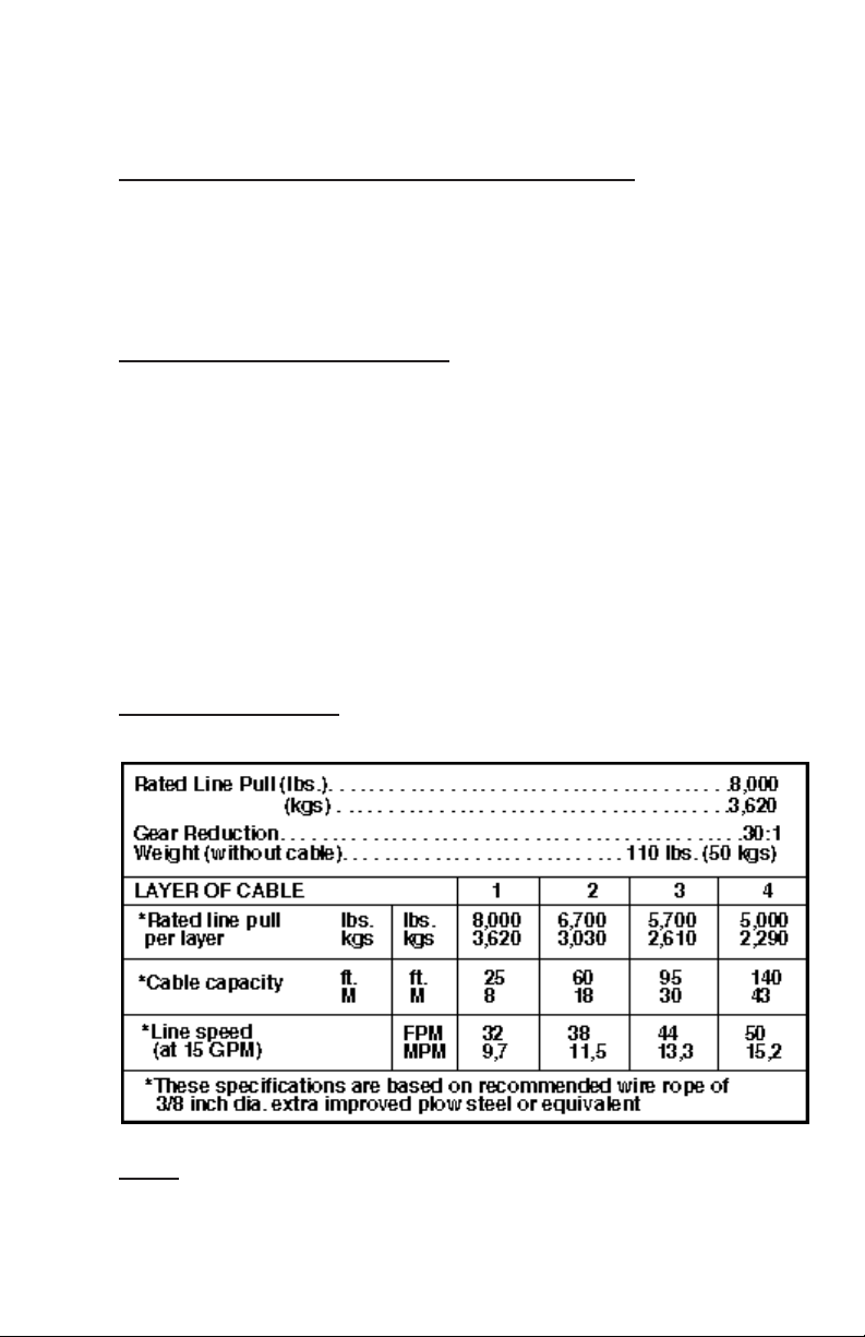
SPECIFICATIONS: CONFORMS TO SAE J706
NOTE: The rated line pulls shown are for the winch only. Consult the wire
rope manufacturer for wire rope ratings.
1
Page 5

TECHNIQUES OF OPERATION
The best way to get acquainted with how your winch operates is to make
test runs before you actually use it. Plan your test in advance. Remember,
you hear your winch, as well as see it operate. Get to recognize the sounds
of a light steady pull, a heavy pull, and sounds caused by load jerking or
shifting. Gain confidence in operating your winch and its use will become
second nature with you.
The uneven spooling of cable, while pulling a load, is not a problem, unless
there is a cable pileup on one end of drum. If this happens reverse the
winch to relieve the load and move your anchor point further to the center
of the vehicle. After the job is done you can unspool and rewind for a neat
lay of the cable.
When pulling a load where there is even a remote chance of cable failure,
place a blanket, jacket or tarpaulin over the cable about six feet behind the
hook. This will slow the snap back of a broken cable and could prevent
serious injury.
NOTE:
respooling unloaded cable onto the drum.
The Ram-Lok®semi-automatic clutch allows rapid unspooling of the cable,
from cable drum, for hooking onto the load. The clutch on the winch is
operated as follows:
1. TO DISENGAGE CL
direction until the load is off the cable. Lift up knob and pull out, lock in
place. See warning label located by shifter knob. The clutch is now locked
out and the cable may be pulled off by hand.
2. TO ENGAGE CL
located by shifter knob. Run the winch in reverse until the shifter knob
snaps fully in or until the cable drum starts turning. At this point make sure
the shifter knob is all the way in. The plastic plug in top of clutch housing
may be removed, for inspection of clutch to assure total engagement. After
the clutch is fully engaged, the winch is ready for winching in the cable.
The Ramsey level winder is an available accessory for tightly
UTCH, run the winch in the reverse (reel out)
UTCH, lift up knob then release. See warning label
2
Page 6
Page 7

2. Check the action of the sliding clutch, making sure it is fully engaging and
disengaging with the cable drum. Remove the plastic plug in top of the
housing and observe if the clutch is fully engaging. If clutch is not fully
engaging, inspect clutch shifter assembly parts, check for damage or
excessive wear and replace as necessary. Observe the jaws on both the
clutch and cable drum, checking for rounding of the driving faces. If
rounding has occurred they should be replaced immediately.
3. Check the winch mounting bolts. If any are missing, replace them and
securely tighten any that are loose. Make sure to use only grade 5 bolts
or better.
4. Check alignment of chain and sprockets and adjust as required to
minimize wear.
5. Inspect the cable. If the cable has become frayed with broken strands,
replace immediately.
C. ANNU
ALLY
1. Drain the oil from the winch annually or more often if winch is used
frequently.
2. Fill the winch to the oil level plug with clean kerosene. Run the winch a
few minutes with no load in the reel in direction. Drain the kerosene from
the winch.
3. Refill the winch to the oil level plug with all purpose E.P. 140 gear oil.
4. Inspect frame and surrounding structure for cracks or deformation.
5. Gear wear can be estimated by rocking the drum back and forth and if
necessary drain oil and remove cover for closer inspection.
CABLE INST
ALLATION
1. Unwind cable by rolling it out along the ground to prevent kinking.
Securely wrap end of cable, opposite hook, with plastic or similar tape to
prevent fraying.
2. Insert the end of cable, opposite hook end, into the 7/16" dia. hole in
drum barrel. Secure cable to drum barrel, using setscrew furnished with
winch. TIGHTEN SETSCREW SECUREL
Y.
3. Carefully run winch in the "reel-in" direction. Keeping tension on end of
cable, spool all the cable onto the cable drum, taking care to form neatly
wrapped layers.
4
Page 8

HYDRAULIC SYSTEMS
FLOW (GPM)
5
0
10
15
7,000
6,000
8,000
20
25
30
35
LINE PULL-FIRST LAYER (LB.)
LINE SPEED-FIRST LAYER (FPM)
STATIC
DYNAMIC
WORKING PRESSURE, PSI
0
0
1,000
1,000
3,000
2,000
5,000
4,000
10
3,0002,000
5
15
HD-200 PERFORMANCE
8,000 LB. DUTY RATING
30:1 GEAR RATIO
(.50 I.D. MINIMUM)
HIGH PRESSURE LINES
LOW PRESSURE LINES
(.75 I.D. MINIMUM)
HYDRAULIC
WINCH MOTOR
CYLINDER SPOOL
3 POSITION 4 WAY
(SUCTION)
PUMP INLET LINE
EMERGENCY STOP
CONTROL VALVE
RELIEF VALVE
FLUID FILTER
FLUID
RESERVOIR
LOW PRESSURE LINES
PUMP
Refer to performance charts, below, to properly match your hydraulic system to the
HD-200 winch performance. The charts consist of:
1. Line pull (lbs.) first layer vs. working pressure (P.S.I.). STATIC (solid line)
refers to hoisting a suspended load from rest; DYNAMIC (dashed line) refers
to maintaining the motion of a moving load.
2. Line speed, first layer (F.P.M.) vs. gallons per minute (G.P.M.).
Performance based on a motor displacement of 3.6 cubic inches with 15 GPM maximum flow rate.
5
Page 9

Page 10

INSTRUCTIONS FOR OVERHAUL OF RAMSEY
MODEL HD-200 RAM-LOK®
DIS-ASSEMBL
1. Drain oil from gear
housing by removing
(item #36) plug from
bottom of gear
housing. Remove
plugs (items #34 &
#35) from top of gear
housing. Remove
adapter rod (item
#26) by driving pin
(item #37) from
shifter shaft of
winch. Remove
mounting frame
(item #1) from winch
by removing hardware
shown.
Y
2. Remove clutch housing (item
#9) and clutch (item #5) from
winch assembly.
Remove two keys (item #31)
from keyways. A screwdriver
can be used, at notch, to aid in
the removal of keys. Once keys
have been removed, drum (item
#7) and thrust washer (item
#46) can be removed from
drum shaft.
7
Page 11

3. Remove motor and coupling (item
#27) from (item #3) adapter by
unscrewing two (item #23)
capscrews with lockwasher.
Remove key (item #11) from
worm shaft. Unscrew four
capscrews (item #19) and remove
adapter from gear housing.
Replace adapter seal (item #41)
and gasket (item #29).
4. Remove bearing cap (item #4) from gear housing by unscrewing
four capscrews (item #19). Remove worm (item #13) and bearings
(item #14) from gear housing. Use soft hammer to gently tap input
end of worm and drive worm and bearing from gear housing. Once
worm has been removed from housing, bearing can be pressed from
end of worm.
Check for signs of
wear or damage to
worm (item #13) and
bearing (item #14).
Replace if necessary.
5. Remove gear housing cover
(item #6) from gear housing
(item #10) by unscrewing
capscrews (item #18). Thread
two of the capscrews into the
two tapped holes of cover and
tighten. This will pull the cover
loose from gear housing.
Remove cover gasket (item
#30) and pull shaft (item #12),
with gear attached, and thrust
washer (item #45) from gear
housing.
8
Page 12

Page 13

10. Check cover bushing (item
#15) for signs of wear. If
necessary remove old bushing
and press bushing into place.
RE-ASSEMBLY
11. Apply grease to end of shaft, opposite gear. Apply grease to
bushing in gear housing (item #10). Place greased end of shaft
through thrust washer (item #46) and bushing in gear housing
(item #10). Place gasket (item #30) onto gear housing
cover (item #6). Apply
grease to gear end of shaft
and cover bushing. Place
cover onto shaft and secure
to housing with ten
(item #18) capscrews.
Tighten capscrews to
8 ft. lbs. (10.8 Nm.) each.
12. Press bearing (item #14) onto worm (item #13). NOTE: Be sure
that thick shoulder of bearings outer race (side with
manufacturer's name and part number) is out, away from worm
threads. Press bearing and worm into gear housing. Slip gasket
(item #29) onto bearing cap (item #4). Use four capscrews (item
#19) to secure cap to gear housing. TIGHTEN CAPSCREWS
TO 8 FT. LBS. (10.8 Nm.) EACH.
10
Page 14

13. Press bearing (item #14) onto worm and into housing. NOTE: Be
sure that thick shoulder of bearings outer race (side with
manufacturer's name and part number) is out, away from worm
threads. Place gasket (item #29) onto adapter (item #3). Attach
adapter to gear housing using four (4)
capscrews (item #22). TIGHTEN
CAPSCREWS TO 12 FT. LBS. (16.3 Nm.)
EACH. Insert key (item #11) into keyway
of worm shaft. Slide tapered end
of coupling (item #27) over end
of worm shaft. Be sure roll
pin (item #38) is in coupling.
Place motor shaft, with
key in keyway, into coupling.
Secure motor to adapter, using
two (2) capscrews (item #23)
and lockwashers. TIGHTEN
CAPSCREWS TO 75 FT. LBS.
(102 Nm.) EACH.
14. Place winch with gear housing cover down on work bench. Drum
shaft should be in vertical position. Slide thrust washer (item #45)
over drum shaft and slide downward until washer rests on gear
housing. Set springs (item #43) into pockets of gear housing with
drag brakes (item #28) on top of springs. Slide drum assembly
(item #7) onto drum shaft with drum jaws upward.
11
Page 15

15. Place thrust washer (item #46) over end of
drum shaft and slide downward until spacer
rests on drum. Press drum downward to
compress springs in gear housing.
Insert keys (item #31) into keyways with
sharp edge of keys pointing outward and
notched end of keys upward. A rubber or
brass mallet will be needed to gently
tap keys into position.
Apply grease to keys and end of shaft.
Place jaw clutch (item #5) over
end of shaft and slide jaw clutch
over keys.
Set clutch housing (item #9) over end of drum shaft. Pull jaw
clutch (item #5) upward, toward clutch housing, enough to allow
yoke, in clutch housing, to fit properly in groove around
jaw clutch.
16. Attach frame assembly
(item #1) using six
capscrews (item #21)
with lockwashers and
two capscrews (item #20)
with lockwasher. Torque
capscrews to 34 ft. lbs.
(46 Nm.) each. Insert plug
(item #36) into bottom of
gear housing. Permatex may
be applied to threads to help
prevent leakage.
Attach adapter rod (item #26) to clutch shaft using pin (item #37).
Pour 3/4 pint of SAE 140 EP gear oil into housing through hole in
top of housing. Insert relief fitting (item #34) into reducer (item
#35). Reducer should then be placed into hole on top of gear
housing. Tighten fitting and reducer securely.
12
Page 16

13
Model HD-200 Ram-Lok
®
Page 17

Page 18

Page 19

Page 20

 Loading...