

Page 1
OPERATING, SERVICE, AND
MAINTENANCE MANUAL
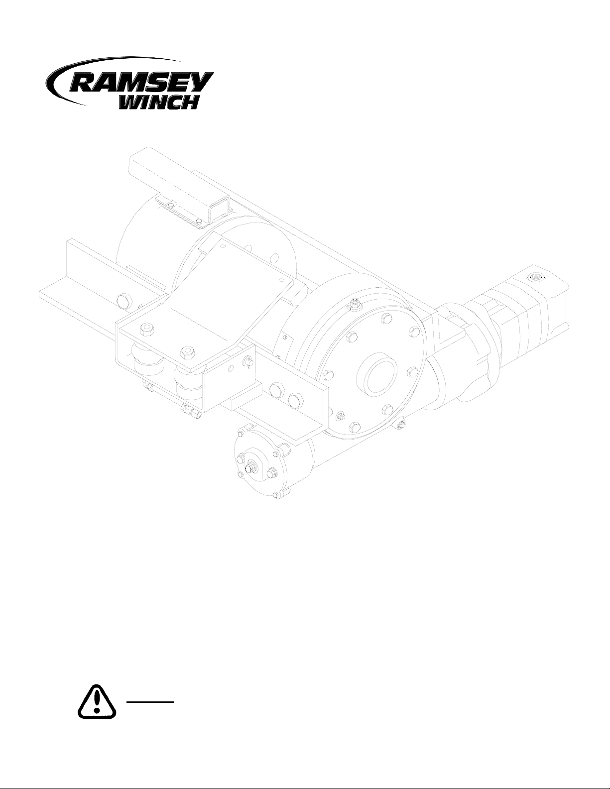
MODEL H-930R
DOW-LOK
®
EQUIPPED
INDUSTRIAL LOW-MOUNT WINCH
PER SZUMMAR SPECIFICATIONS
CAUTION: READ AND UNDERSTAND THIS MANUAL BEFORE INSTALLATION AND
OPERATION OF WINCH. SEE WARNINGS!
Page 2

TABLE OF CONTENTS
INTRODUCTION . . . . . . . . . . . . . . . . . . . . . . . . . . . . . . . . . . . . . . . . . . . . . . . . . . . . . . . . . . .1
WARRANTY INFORMATION . . . . . . . . . . . . . . . . . . . . . . . . . . . . . . . . . . . . . . . . . . . . . . . . . .1
SPECIFICATIONS . . . . . . . . . . . . . . . . . . . . . . . . . . . . . . . . . . . . . . . . . . . . . . . . . . . . . . . . . .1
WARNINGS . . . . . . . . . . . . . . . . . . . . . . . . . . . . . . . . . . . . . . . . . . . . . . . . . . . . . . . . . . . . . .1
HYDRAULIC SYSTEM REQUIREMENTS . . . . . . . . . . . . . . . . . . . . . . . . . . . . . . . . . . . . . . . . .2
PERFORMANCE CHARTS . . . . . . . . . . . . . . . . . . . . . . . . . . . . . . . . . . . . . . . . . . . . . . . . . . .2
TYPICAL LAYOUT . . . . . . . . . . . . . . . . . . . . . . . . . . . . . . . . . . . . . . . . . . . . . . . . . . . . . . . . .2
TECHNIQUES OF OPERATION . . . . . . . . . . . . . . . . . . . . . . . . . . . . . . . . . . . . . . . . . . . . . . . .3
AIR SYSTEM REQUIREMENTS . . . . . . . . . . . . . . . . . . . . . . . . . . . . . . . . . . . . . . . . . . . . . . . .3
CABLE TENSIONER OPERATION . . . . . . . . . . . . . . . . . . . . . . . . . . . . . . . . . . . . . . . . . . . . . .3
WINCH MOUNTING . . . . . . . . . . . . . . . . . . . . . . . . . . . . . . . . . . . . . . . . . . . . . . . . . . . . . . . .3
WINCH MAINTENANCE . . . . . . . . . . . . . . . . . . . . . . . . . . . . . . . . . . . . . . . . . . . . . . . . . . . . .4
CABLE INSTALLATION . . . . . . . . . . . . . . . . . . . . . . . . . . . . . . . . . . . . . . . . . . . . . . . . . . . . . .4
ADJUSTING THE OIL COOLED WORM BRAKE . . . . . . . . . . . . . . . . . . . . . . . . . . . . . . . . . . . .5
SERVICING THE OIL COOLED WORM BRAKE . . . . . . . . . . . . . . . . . . . . . . . . . . . . . . . . . . . .5
RE-ASSEMBLING AND CHECKING THE BRAKE . . . . . . . . . . . . . . . . . . . . . . . . . . . . . . . . . . .6
TEST FOR PROPER BRAKE ASSEMBLY . . . . . . . . . . . . . . . . . . . . . . . . . . . . . . . . . . . . . . . . .6
TROUBLESHOOTING . . . . . . . . . . . . . . . . . . . . . . . . . . . . . . . . . . . . . . . . . . . . . . . . . . . . . . .7
INSTRUCTIONS FOR OVERHAUL . . . . . . . . . . . . . . . . . . . . . . . . . . . . . . . . . . . . . . . . . . .8-16
DIMENSIONAL DRAWING . . . . . . . . . . . . . . . . . . . . . . . . . . . . . . . . . . . . . . . . . . . . . . . . . .17
PARTS LIST AND PART DRAWING . . . . . . . . . . . . . . . . . . . . . . . . . . . . . . . . . . . . . . . . .18-19
LIMITED WARRANTY . . . . . . . . . . . . . . . . . . . . . . . . . . . . . . . . . . . . . . . . . . . . .BACK COVER
Page 3

RAMSEY MODEL H-930 DOW-LOK
®
PLEASE READ THIS MANU
AL CAREFULLY
This manual contains useful ideas in obtaining the most efficient operation from your Ramsey Winch, and safety procedures one needs to know before operating a Ramsey Winch. Do not operate this winch until you have carefully
read and understand the "WARNINGS" and "OPERATION" sections of this manual.
W
ARRANTY INFORMATION
Ramsey Winches are designed and built to exacting specifications. Great care and skill go into every winch we
make. If the need should arise, warranty procedure is outlined on the back of your self-addressed postage paid warranty card. Please read and fill out the enclosed warranty card and send it to Ramsey Winch Company. If you have
any problems with our winch, please follow instructions for prompt service on all warranty claims. Refer to back
page for limited warranty.
SPECIFICA
TIONS (Conforms to SAE J706)*
NOTE: The rated line pulls shown are for the winch only. Consult the wire rope manufacturer for wire rope ratings.
W
ARNINGS:
CLUTCH MUST BE TOTALLY ENGAGED BEFORE STARTING THE WINCHING OPERATION.
DO NOT START WINCH MOTOR BEFORE ENGAGING CLUTCH
DO NOT DISENGAGE CLUTCH UNDER LOAD.
STAY OUT FROM UNDER AND AWAY FROM RAISED LOADS.
STAND CLEAR OF CABLE WHILE PULLING. DO NOT TRY TO GUIDE CABLE.
DO NOT EXCEED MAXIMUM LINE PULL RATINGS SHOWN IN TABLE.
DO NOT USE WINCH TO LIFT, SUPPORT, OR OTHERWISE TRANSPORT PEOPLE.
A MINIMUM OF 5 WRAPS OF CABLE AROUND THE DRUM BARREL IS NECESSARY TO HOLD THE LOAD.
CABLE ANCHOR IS NOT DESIGNED TO HOLD LOAD.
1
Rated Line Pull (lbs.)
…………………………………………………
30,000
(Kg.)
…………………………………………………
13,590
Gear Reduction
…………………………………………………………
41:1
Weight (without cable) …………………………………………522 lbs. (237 Kg.)
12345
lbs. 30,000 25,200 21,700 19,100 17,000
Kg. 13,600 11,430 9,840 8,660 7,710
ft. 25 55 85 135 185
m 7 16 28 41 56
FPM1112141617
MPM 3.3 3.6 4.3 4.9 5.2
* These specifications are based on recommended wire rope of 5/8" inch
(16mm) 6x19 extra improved plow steel
LAYER OF CABLE
*Rated line pull
per layer
*Cable Capacity
*Line Speed @
30 GPM
Page 4
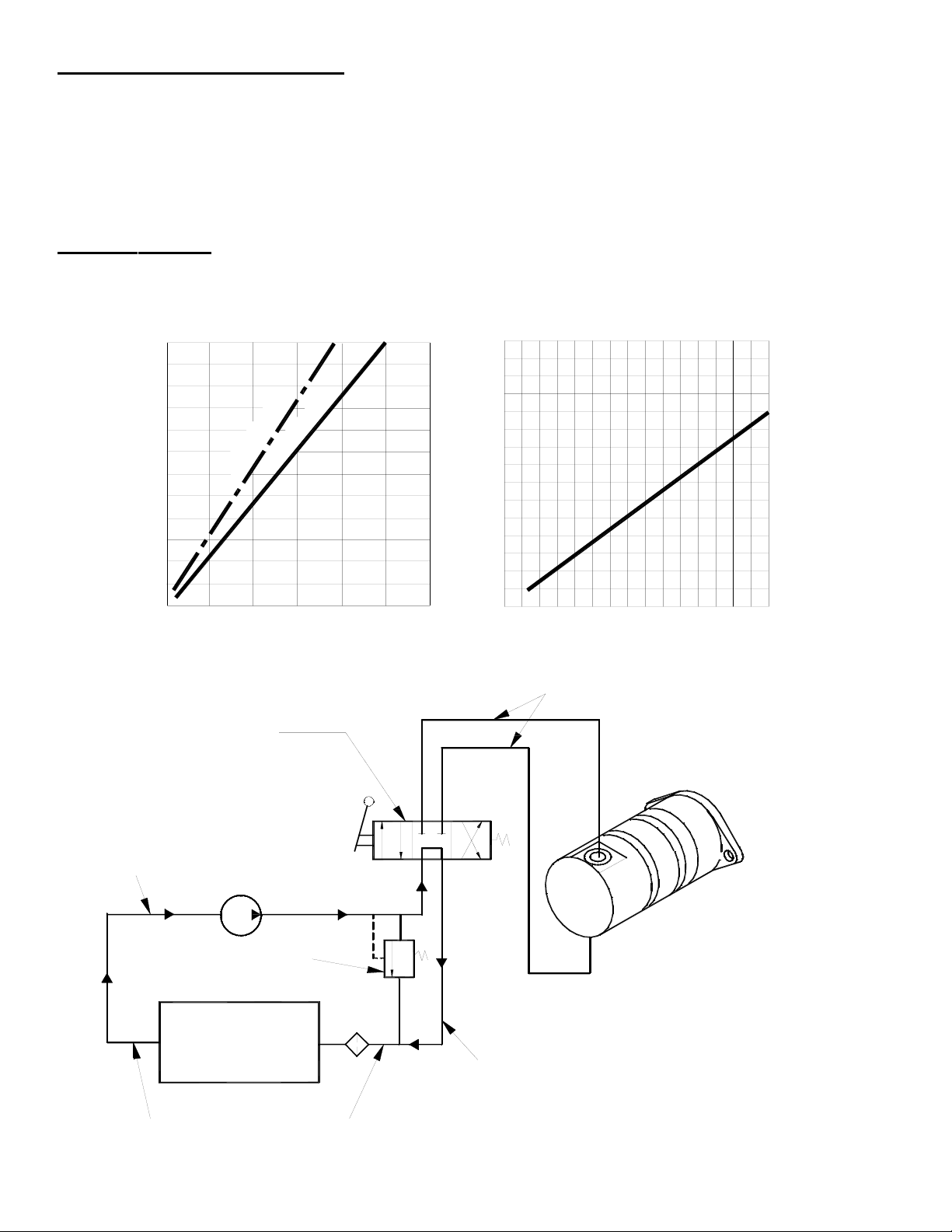
HYDRAULIC SYSTEM REQUIREMENTS
Refer to the performance char ts, below, to properly match your hydraulic system to the H-930 Model winch performance. The
charts consist of :
(1) Line pull (lb.) first layer vs. working pressure (PSI)
(2) Line speed, first layer (FPM) vs. gallons per minute (GPM).
Performance based on a motor displacement of 24 cubic inches with 30 GPM maximum flow rate. See page 17 for motor port
size.
H-930 Performance
30,000 lb. Duty Rating
41:1 Gear Ratio
2
LOW PRESSURE LINES
(.88 I.D. MINIMUM)
HIGH PRESSURE LINES
WINCH MOTOR
HYDRAULIC
LOW PRESSURE LINES
FLUID FILTER
RELIEF VALVE
PUMP
RESERVOIR
FLUID
4 WAY, 3 POSITION
CONTROL VALVE
(SUCTION)
PUMP INLET LINE
VALVE (CYLINDER SPOOL)
(1.31 I.D. MINIMUM)
GALLONS PER MINUTE
20
LINE PULL, LBS., FIRST LAYER
5,000
0
0
20,000
15,000
10,000
30,000
25,000
LINE SPEED, FPM, FIRST LAYER
3,000
WORKING PRESSURE, P.S.I.
2,0001,000 0
0
10
DYNAMIC
STATIC
5
10
15
30
Page 5

TECHNIQUES OF OPERATION
The best way to get acquainted with how your winch operates is to make test runs before you actually use it. Plan your test in
advance. Remember, you hear your winch, as well as see it operate. Get to recognize the sounds of a light steady pull, a heavy
pull, and sounds caused by load jerking or shifting. Gain confidence in operating your winch and its use will become second
nature with you.
The uneven spooling of cable, while pulling a load, is not a problem, unless there is a cable pileup on one end of drum. If this
happens, reverse the winch to relieve the load and move your anchor point further to the center of the vehicle. After the job is
done you can unspool and rewind for a neat lay of the cable.
The Dow-lok® clutch provides free spooling and clutch engagement with the cable drum. With the clutch disengaged, the cable
can be freespooled off the drum. For winching in the load, the clutch must be fully engaged with the drum.
TO DISENGAGE THE CLUTCH:
Run winch in the "out" direction until there is no load on the cable. Apply 70-90 psi to the air shift cylinder to disengage the
clutch. Do not disengage the clutch under load.
TO ENGAGE THE CLUTCH:
There must be a minimum of 1 foot of slack in the cable before attempting to engage the clutch. This will allow the drum to
rotate a minimum of 1/4 turn allowing engagement of the clutch before picking up the load. With this slack in the cable, exhaust
air pressure from the air shift cylinder and then run the winch in the "in" direction until the clutch springs into engagement and
the drum starts to turn. Clutch must be fully engaged before star ting the winching operation.
AIR SYSTEM REQUIREMENTS
The cable tensioner requires an independent, adjustable regulated air supply of between 50 and 90 PSI. An air regulator kit,
Ramsey Part No. 256092 is recommended.
CAUTION: DO NOT EXCEED 100 PSI TO THE CABLE TENSIONER ACTUATORS. THIS COULD CAUSE DAMAGE
TO THE ACTUATORS.
The inlet port of the air cylinder clutch requires a separate regulated air supply of 70-90 PSI.
CABLE TENSIONER OPERATION
If you remove the cable entirely from the winch or this is a new installation: The cable tensioner is not
intended to be energized on a bare drum. Before applying air to the cable tensioner, install the cable.
To adjust the free spool effort of the cable tensioner: Disengage the winch clutch and freespool some cable off
the drum. Adjust the air pressure to the cable tensioner to achieve the desired free spool effort that also prevents
“bird-nesting” of the cable.
WINCH MOUNTING
It is most important that this winch be mounted securely so that the three major sections (the clutch housing end, the cable
drum, and the gear housing end) are properly aligned.
This Model H-930 winch is furnished with mounting angles. Angle size is 1/2” x 4 x 4 high strength steel angle.
3
Page 6

WINCH MAINTENANCE
Adhering to the following maintenance schedule will keep your winch in top condition and performing as it should with a minimum of repair.
A. WEEKLY
1. Check the oil level and maintain it to the oil level plug with SAE 140 EP gear oil. If oil is leaking out, determine location and
repair.
2. Check the pressure relief plug in top of the gear housing. Be sure that it is in good operating condition so that hot oil gases
may escape.
3. Lubricate cable with light oil.
B. MONTHLY
1. Lubricate the various grease fittings located in the cable drum, end bearing, clutch housing, or clutch operating linkage. Any
good grade of moly-disulfide containing grease is acceptable.
2. Check the action of the locking ring. Make sure it is spring loaded and free to move fully against the cable drum in the
engaged position and that it is pulled fully away from the cable drum and latched when disengaged.
3. Check the winch mounting bolts. If any are missing, replace them and securely tighten any that are loose. Use grade 5 or
better bolts.
4. Check the torque setting of the oil cooled worm brake. Make any adjustments required, following the procedure described
in Adjusting the Oil Cooled Worm Brake in this manual.
5. Inspect the cable. If the cable has become frayed with broken strands, replace immediately.
C. ANNUALLY
1. Drain the oil from the winch annually or more often if winch is used frequently.
· After draining, fill the winch to the oil level plug with clean kerosene.
· Run the winch a few seconds with no load in the “Reel In” direction.
· Drain the kerosene completely from the winch.
· Refill the winch with 4 pints all purpose SAE 140 EP gear oil.
2. Inspect frame and surrounding structure for cracks or deformation.
3. Gear wear can be estimated by rocking the drum back and forth and if necessary drain oil and remove cover for closer
inspection.
CABLE INSTALLATION
1. Unwind cable by rolling it out along the ground to prevent kinking. Securely wrap end of cable, opposite hook, with plastic
or similar tape to prevent fraying.
2. Insert the end of cable, opposite hook end, under drum and into the hole in drum barrel. Secure cable to drum barrel, using
setscrew furnished with winch. TIGHTEN SETSCREW SECURELY.
3. Carefully run winch in the “reel-in” direction. Keeping tension on end of cable, spool all the cable onto drum, taking care to
form neatly wrapped layers.
The wire rope can easily be removed from the drum by loosening the setscrew.
4
Page 7
ADJUSTING THE OIL COOLED WORM BRAKE
The oil cooled, fully adjustable, automatic worm brake operates in the worm housing lubricant, all parts being submerged in oil.
When the brake wears to the point that the load begins to drift, the brake can be adjusted as follows:
1. Loosen the adjusting screw lock nut.
2. Tighten the brake by turning the adjusting screw clockwise. CAUTION: Only 1/4 turn is usually required to adjust the brake.
Over-tightening can cause over-heating, and damage to the brake parts. Tighten the lock nut after adjustment is completed.
If the brake does not respond to adjustment then a new leaf spring and brake disc is needed.
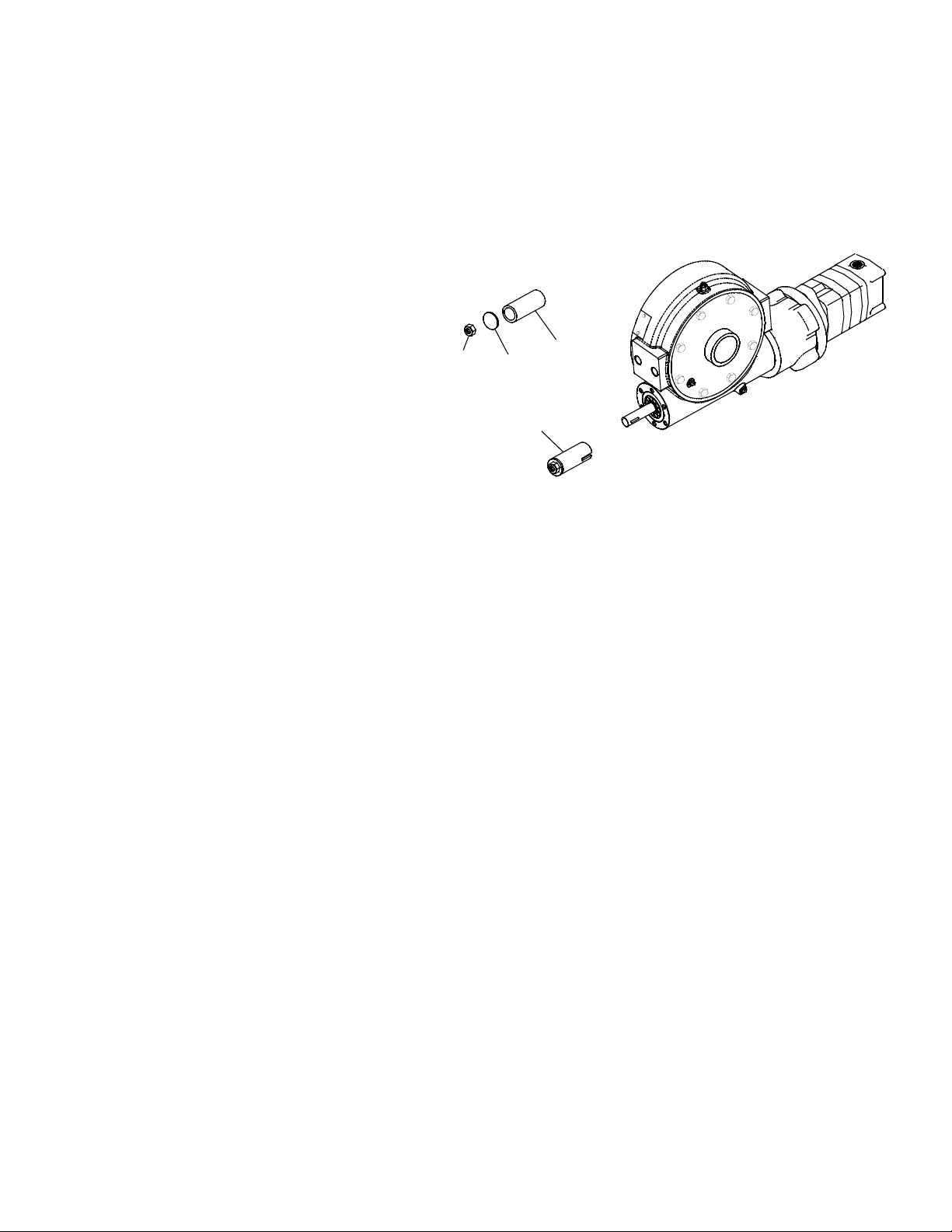
A torque wrench can be equipped with a special adapter to
fit the input shaft (worm) of the winch. The adapter can be
made by welding a nut to the end of a piece of tubing as
shown in the following figure.
After welding the cap and nut to the tubing, slot the tubing,
as shown. This will allow the special adapter to slide over
the keyway and will then act as a large socket. A torque
wrench can then be used to apply the proper torque. Turn
the torque wrench so that the drum turns in the spool out
direction or lowering direction. The torque rating for the
brake on the Model H-930R Dow-Lok should be 65 to 75
ft. lbs. (90-100 Nm) If torque wrench does not show the
proper value as it turns, then the worm brake adjusting bolt
should be turned clockwise 1/4 turn. Each time the adjusting bolt is turned, check the torque reading. Continue this procedure
until the proper torque reading is achieved. Then tighten the lock nut.
SERVICING OF THE OIL COOLED WORM BRAKE
1. Remove the drain plug and drain the worm gear oil from the worm housing.
2. Back off the lock nut, then the adjusting screw, both two turns or more by turning them counter-clockwise.
3. Remove the cover mounting screws.
4. Remove the cover along with coil spring and leaf spring.
5. Remove the retainer plate, composition brake disc, cam plate and balls.
6. Inspect parts as follows:
a) Composition brake discs are 1/4" thick when new. Replace if thinner than 3/16” or if surfaces are glazed or burnt.
b) Inspect the flat, ground surface of the cam plate and retainer plate for glazing, warpage, or other damage. Glazing can be
removed by scraping carefully.
c) Inspect the leaf spring. It should be bowed 1/8".
5
ADAPTER
CAP
NUT
TUBING
SOCKET
Page 8
6
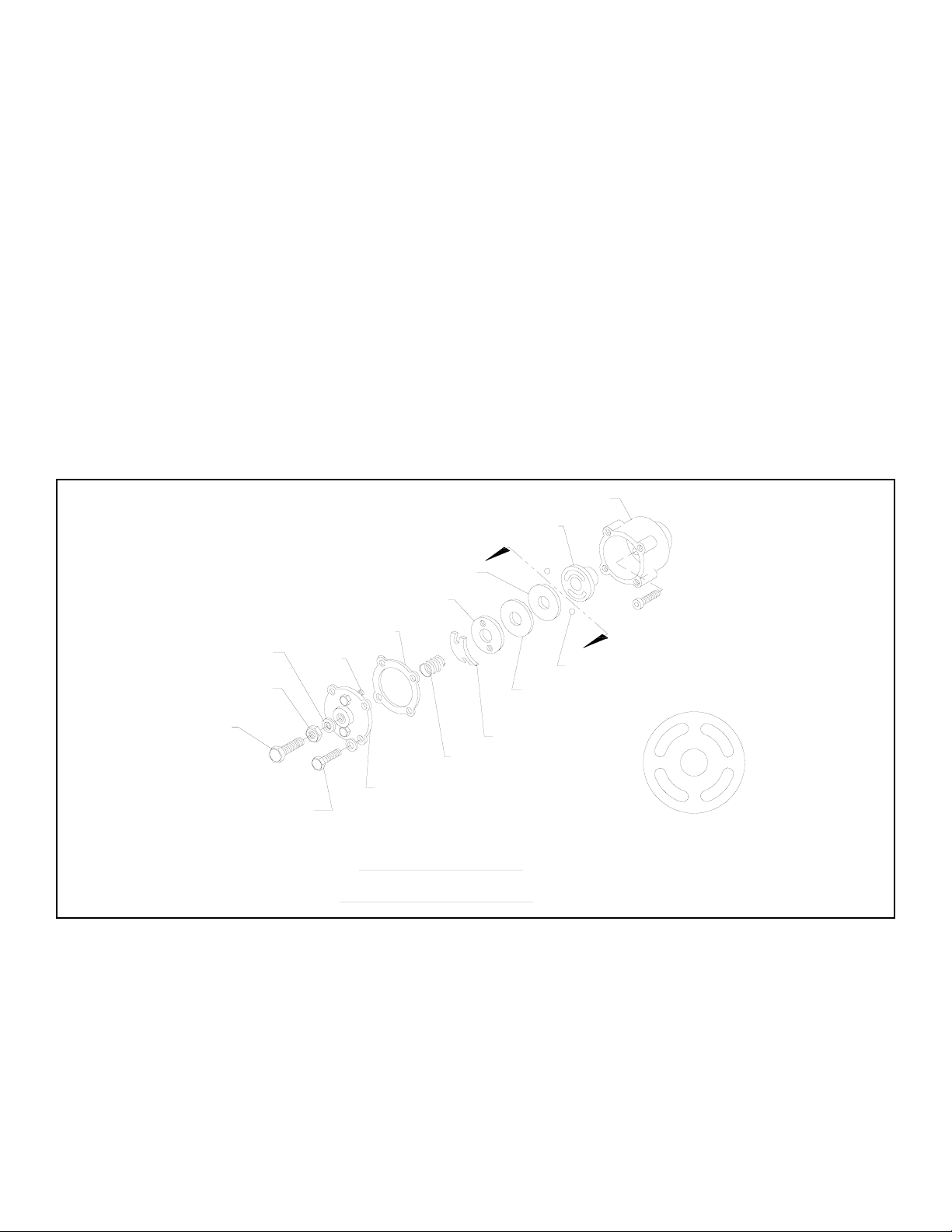
RE-ASSEMBLING AND CHECKING THE BRAKE
1. Press brake hub into place over worm shaft and key.
2. Assemble balls in slot #1 of cam. Use stiff grease to hold balls in place and slide cam over end of worm. Be sure that
balls are secure, between cam slots and hub slots.
3. Install brake disc.
4. Install retainer plate, smooth side toward brake disc.
5. Install the gasket on the cover with a small amount of grease or sealer.
6. The coil spring goes over the adjusting screw on the inside of the cover.
7. Install the notches of the leaf spring on the pins protruding through the cover. The hollow side of the leaf spring goes
toward the brake.
8. Install brake housing cover, making sure the protruding pins go through the leaf spring and into the holes in the retainer
plate.
9. Bolt cover into place with the mounting screws. Apply Loc-tite PST #567 thread sealer to drain plug, install drain plug and
add 4 pints all purpose SAE 140 EP gear oil. Refer to Instructions for Overhaul for more information on assembling winch.
10. Turn winch in the hoisting direction at least one turn of the input shaft.
11. Turn the adjusting screw in until it is finger tight. Tighten jam nut to lock adjusting screw.
TEST FOR PROPER BRAKE ASSEMBLY
After the brake has been adjusted to the proper torque setting disengage clutch. Start vehicle engine and run winch in the reel
in (hoisting direction). Allow winch to run in this direction for one minute.
Place your hand on the safety brake housing. If housing is not hot to the touch then run winch in the reverse direction (cable
out) for one minute. Brake housing should begin to heat.
When these conditions exist, proper installation has been made. If heating becomes noticeable when running the winch in forward rotation (hoisting direction), the brake should be again disassembled. When disassembled, confirm that the balls are in
slot #1 of cam, then carefully follow the instructions for re-assembling and checking the brake.
WORM BRAKE
LEAF SPRING
COIL SPRING
BRAKE HOUSING
COVER
MOUNTING
SCREW
ADJUSTING
SCREW
DIAGRAM 1
BRAKE COVER
THREAD SEAL
JAM NUT
RETAINER PLATE
CAM PLATE
GASKET
PIN
A
BRAKE DISC
(LOOKING AT CAM
PLATE FROM WINCH)
VIEW
A-A
1
2
1
2
COMPOSITION
A
BALL
HUB
Page 9

7
CONDITION POSSIBLE CAUSE CORRECTION
Dry or rusted shaft. Clean and lubricate.
Bent yoke or linkage Replace yoke or shaft assembly
Debris in clutch Clean and lubricate.
Clutch not disengaging, drum does
not freespool
Adjust clutch air shifter. See page 15.
Seal damaged or worn Replace seal.
Too much oil. Drain excess oil. Refer to Techniques of Operation, page 3.
Damaged gasket Replace gasket
Safety brake has become worn.
Replace brake disc. See Servicing of the Oil Cooled Safety
Brake, page 5.
Safety brake out of adjustment
Turn adjusting bolt clockwise 1/4 turn or until load does not
drift.
Hydraulic motor worn out. Replace motor.
Low flow rate.
Check flow rate. Refer to Hydraulic Systems Performance
Chart, page 2.
Winch not mounted squarely,
causing end bearings to bind drum.
Check mounting. Refer to Winch Mounting, page 3.
Clutch not disengaged.
Check air pressure to clutch cylinder--70 psi minimum
required. See page 17.
Excessive air pressure to cable
tensioner
Adjust air pressure to cable tensi oner. Do not exceed 100
PSI. See Cable Tensioner Operation , page 3.
CABLE BIRDNESTS WHEN CLUTCH IS
DISENGAGED
Drag brake disc worn. Replace discs.
HYDRAULIC FLUID LEAKS FROM HOLE
IN MOTOR ADAPTER
Damaged motor shaft seal. Replace seal.
CABLE DRUM WILL NOT FREE SPOOL
TROUBLESHOOTING GUIDE
OIL LEAKS FROM HOUSING
LOAD DRIFTS DOWN
WINCH RUNS TOO SLOW
CLUTCH INOPERATIVE OR BINDS UP
Page 10

INSTRUCTIONS FOR OVERHAUL
Refer to parts lists and parts drawing
for corresponding part numbers.
1. Shift clutch into engaged “IN”
position. Drain oil from gear
housing by removing plug (item
#93) from end bearing.
Remove frame angles (items #4
& #5) from winch by removing
capscrews (item #56 & #57)
with lockwashers (item #77)
If cable tensioner does not need
to be serviced, disconnect air
supply from T connector and
leave tensioner assembled to
frame angle. If cable tensioner
does need service, refer to Cable Tensioner Overhaul, page 16.
2. If the air cylinder and shifter needs to be
removed, remove (4) capscrews (item
#46) that hold shifter cover (item #43)
and shifter bracket (item #40) onto
clutch housing (item #20). Remove cotter pin (item #78) and clevis pin (item
#79) that hold clevis (item #30) to yoke
(item #35). Loosen jam nuts (item #66)
and unscrew stud (item #106) from clevis and air cylinder (item #83).
To remove air cylinder from shifter bracket, remove (4) capscrews (item #64) and
lockwashers (item #70).
Remove clutch housing from end of drum
shaft along with yoke (item #35).
NOTE: It will be necessary to pull the
yoke upward inside the clutch housing as
far as it will go in order to clear the locking ring attached to the drum. Press in on retainer plate (item #99) to
relieve spring tension and remove the retainer ring (item #31).
93
77
56
77
57
56
77
4
5
57
77
40
106
102
99
105
31
44
79
78
30
66
20
55
35
46
64
60 65
70
83
43
8
Page 11

3. Slide the locking ring (item #12) from the clutch. NOTE: The locking
ring cannot be removed unless the clutch is engaged, with dowel
pins (item #96) seated in the shaft keyways.
Rotate the drum so the (8) balls (item #37) and (4) dowel pins
(item #96) can be removed.
If necessary, the clutch (item #10) may be disassembled from the
drum by removing the (8) capscrews (item #52). Slide drum (item
#1) from drum shaft.
4. Remove motor (item #90) from adapter
plate (item #27) by removing capscrews
(item #62). Remove adapter plate and
coupling (item #11) from adapter (item
#3) by removing (8) capscrews (item
#58).
Remove the key (item #23) from motor
side of worm shaft. Unscrew (6) capscrews (item #61) and remove adapter
from gear housing. Replace adapter seal
(item #100) and gasket (item #84).
The drag brake disc (item #16), spacer
(item #109), and spring (item #104)
should be examined and replaced if necessary.
5. For further instructions, refer to Servicing the Oil
Cooled Safety Brake on page 5. Remove brake housing (item #18) from gear housing by removing (6)
capscrews (item #61). Remove key (item #24) from
brake side of worm. Remove worm (item #34) and
bearings (item #38) from gear housing. Use a soft
hammer to gently tap input end of worm and drive
worm and bearing from gear housing. Once worm
has been removed from gear housing, bearing can be
pressed from end of worm.
Check for signs of wear or damage to worm and
bearings. Replace if necessary.
37
52
12
84
3
100
61
11
58
104
16
109
62
27
90
38
23
9
38
38
24
34
84
61
18
Page 12

6. Remove gear housing cover (item #14) from gear hous-
ing (item #19) by removing (8) capscrews (item #48).
Thread (2) of the capscrews into the two tapped holes of
cover and tighten until the cover comes loose from the
gear housing.
Remove the cover gasket (item #86) and pull shaft (item
#29), with gear attached, from gear housing.
7. Check for signs of wear on gear teeth. If necessary, remove gear with hub attached from shaft by sliding gear to
end of shaft. Disassemble the gear from the hub by removing (10) capscrews (item #54) and washers (item #74).
Replace gear, hub, shaft, or keys as needed.
8. To replace gear and hub onto shaft:
a. Tap keys (item #25) into short keyways of drum shaft
(item #29).
b. Press shaft (item #29) and keys through gear hub
(item #22) until end of keys on long end of shaft are
flush with hub.
c. Align holes in gear (item #17) with holes in gear hub (item #22). Press gear into hub. Be sure gear is seat-
ed all the way on the hub. Secure gear to hub using (10) capscrews (item #46) with lockwashers (item
#64. Tighten to 121 ft-lbs. (164 Nm) torque each.
10
14
48
86
29
19
Page 13

9. Check gear housing bushing (item #8) and o-ring (item
#91) for signs of wear. Replace if necessary by pressing old
bushing from gear housing. Press new bushing into place
and insert new o-ring into groove inside of bushing.
10. Check drum bushings (items #41 and #42) for
signs of wear. Replace if necessary by pressing
old bushings from drum (item #1). Press bushing (item #41) into bore in drum until its flange
is seated against bottom of counterbore. Press
bushing (item #42) into opposite bore on drum
until end of bushing extends .5” from end of
drum.
11. Check end bearing bushing (item #42) for signs of
wear. If necessary, remove old bushing and press
new bushing into place.
12. Check end bearing cover bushing (item #8) and o-
ring (item #91) for signs of wear. Replace if necessary by pressing old bushing from gear housing.
Press new bushing into place and insert new o-ring
into groove inside of bushing.
91
19
8
11
Page 14

13. Apply grease to end of shaft, opposite gear. Apply grease
to bushing in gear housing (item #19). Place greased
end of shaft through bushing in gear housing. Place gasket (item #86) onto gear housing cover (item #19).
Apply grease to gear end of shaft and cover bushing.
Place cover onto shaft and secure to housing with (8)
capscrews (item #48). Tighten capscrews to 39 ft-lbs.
(52 Nm) each.
14. Press bearing (item #38) onto worm (item
#34). NOTE: Be sure that thick shoulder of bearing’s outer race (side with manufacturer’s name
and part number) is out, away from worm
threads. Press bearing and worm into gear housing.
Slip gasket (item #84) onto brake housing (item
#18). Use (6) capscrews (item #61) to secure
brake housing to gear housing. Tighten capscrews to 45 ft-lbs. (61 Nm) each.
Place key (item #24) into keyway of worm (item
#34). Refer to Reassembling and Checking the
Brake, page 6 .
15. Press bearing (item #38) onto worm and into
housing. NOTE: Be sure that thick shoulder of
bearing’s outer race (side with manufacturer’s
name and part number) is out, away from worm
threads. Attach adapter (item #3) to gear housing using (6) capscrews (item #61). Tighten
capscrews to 45 ft-lbs. (61 Nm) each.
Insert key (item #23) into keyway of worm
shaft. Slide coupling (item #11) over end of
worm shaft. Attach adapter plate (item #27) to
adapter using (8) capscrews (item #58).
Tighten capscrews to 21 ft-lbs (28 Nm) each.
Place motor shaft, with key in keyway, into coupling. Secure motor to adapter, using (2) capscrews (item #62). Tighten capscrews to 102
ft-lbs. (138 Nm) each.
14
48
86
29
19
84
38
61
24
34
18
12
84
3
100
61
11
58
104
16
109
62
27
90
38
23
Page 15

16. Place winch with gear housing cover down on work bench.
Drum shaft should be in a vertical position. Set springs (item
#104) into pockets of gear housing with drag brakes (item
#16) on top of disc (item #109) and springs. Slide drum
assembly onto drum shaft.
17. Place clutch (item #10) over end of drum shaft. Align clutch
over the pilot bushing in drum. Install (8) capscrews (item
#52) and tighten the capscrews to 103 ft-lbs. (139 Nm)
torque to securely seat the clutch to the drum.
Rotate the drum to align the clutch slots with the shaft keyways. Lightly grease (4) dowel pins (item #96) and (8) balls
(item #37) with molybdenum disulfide or graphite bearing
grease. Insert the dowel pins and balls. In the engaged position the balls are nearly flush with the clutch.
Lightly grease the internal and external groove and bore in
locking ring (item #12) and clutch (item #10).
Slide locking ring onto clutch. When fully engaged, the locking ring touches the clutch flange and there is .71 to .73
inches (18 to 18.5 mm) between the end of the locking ring
and the end of the clutch.
18. Lightly grease the (4) springs (item #105) and place
over (4) roll pins (item #95) on retainer plate (item
#99).
NOTE: If roll pins (items #95 and #97) are damaged,
remove and install new pins as follows:
Insert four roll pins (item #95) into same retainer plate
holes. Drive pins into plate until pins extend 5/16”
through the clutch housing side of the retainer plate.
Drive roll pins (item #97) into ends of pins (item #95)
that extend 5/16” beyond retainer plate, until ends of
roll pins are flush. Check to make sure that roll pins
still extend 5/16” through retainer plate.
Install spacer (item #31), retainer plate, with springs,
and secure using (4) capscrews (item #44). Tighten capscrews to 9.7 ft-lbs (13 Nm) each. Firmly seat the retainer
ring (item #102) into drum shaft groove.
37
52
12
13
105
99
102
31
44
95
97
Page 16

19. Set the yoke (item #35) so that the screw heads (item #60) engage the external groove in the locking ring.
Push the clutch housing (item #20) onto the drum shaft and latch the shifter assembly in the engaged “IN” position. Insert the (2) capscrews (item #55) and securely tighten.
Attach mounting angles (items #4 & 5) to winch assembly using (4) capscrews (item #56) and lockwashers
(item #77), at clutch housing, and (4) capscrews (item #57) and lockwashers (item #77) at gear housing.
Tighten capscrews to 500 ft-lbs (678 Nm) each.
20. Apply Loc-tite PST #567 thread sealer to the pipe
plug (item #93). Insert plug into bottom of gear
housing. Remove reducer and relief fitting (items
#87 and #92) from top of gear housing. Pour 4
pints of SAE 140 EP gear oil into hole. Apply Loctite PST #567 thread sealer to the reducer and
relief fitting and replace. Oil level can be checked
at oil level plug.
60 65
35
20
55
56
57
77
77
4
77
77
5
56
56
14
93
92
87
Page 17

21. Install airshifter bracket (item #40) using (2)
capscrews (item #46), reserving the other (2)
capscrews to install the cover later. Tighten to 18
ft-lbs. torque. Install the air cylinder (item #83)
using (4) screws and lockwashers (items #64
and #70). Tighten these screws to 45 in.-lbs.
22. Apply Loc-tite #262 to stud (item #106). Install (2) jam
nuts (item #60) onto stud, then attach stud to air cylinder
shaft. Screw clevis (item #30) to other end of stud and
adjust stud until back of clevis is 1 1/8” from bracket
(item #40), as shown at right.
23. Pull yoke to fully engaged position, and attach clevis to
shifter using pin (item #79), securing with cotter pin (item
#78). Confirm that clevis pin is not in a bind when shifter
is in engaged position. Adjust stud slightly if it is. Tighten
jam nuts to keep stud in correct position.
24. Connect air pressure (70-90 PSI) to inlet port of air cylinder
and disengage clutch. Confirm that clutch is fully disengaged
and freespool winch. Release air pressure and confirm that
travel of air cylinder shaft is 1/8 to 3/16”. Continue to freespool
winch and confirm that winch shifts to full engagement.
25. Install air cylinder cover (item #43) using (2) capscrews (item
#46). Tighten to 18 ft-lbs. torque.
26. Operate winch forward and reverse and confirm that drum
rotates.
15
18 ft-lbs
Torque
45 in-lbs.
Torque
70 64
30
43
83
106
40
46
78
60
79
30
40
1-1/8"
Page 18

Cable Tensioner Overhaul
1. Disconnect the air supply from the cable tensioner at the
“T” fitting (item #80). It is not necessary to remove the
tensioner bracket and spacer from the frame angles to
replace the tensioner bar or actuators.
2. Remove nuts (item #69) from actuators (item #82) that
hold the actuators to the tensioner assembly (item #2).
Remove pin (item #26) by removing cotter pin (item
#78) and washer (item #76) on both sides.
3. Remove the tensioner assembly (item #2) and inspect
the actuators for damage.
4. Remove and replace any damaged parts. Tighten cap-
screws (item #49) that attach tensioner bar (item #6) to
tensioner assembly to 30 ft.-lbs (41 Nm) torque.
5. Insert the pin (item #26) through the bracket (item #39)
and secure with the washers (item #76) and cotter pins
(item #78). Replace nuts (item #69) and tighten to 10 ftlbs. (13.5 Nm) torque.
6. Center the tensioner bar between the drum flanges.
Loosen (but do not remove) the mounting bolts (item
#51) and center with a scale or tape measure. Tighten
the mounting bolts to 87 ft-lbs (118 Nm) torque.
7. Reconnect the air supply to the “T” fitting (item #80) on
the cable tensioner. Do not tighten more than 1/4 turn
beyond hand tight. If the cable was removed, do not
energize the cable tensioner until the cable is
installed. See Cable Installation, page 4.
16
51
2
69
78
82
33
32
81
26
39
76
69
75
4
68
69
78
94
6
49
76
80
AIR SUPPLY
CONNECTS
HERE
Page 19

17
(70 PSI MIN.)(90 PSI MAX.) FOR DISENGAGING
CLUTCH. (CLUTCH IS SPRING ENGAGED)
CABLE "OUT" ROTATION
(REF) 5/8 DIAMETER CABLE
DIMENSIONS SHOWN ARE INCHES OVER MILLIMETERS
1 1/16-12 O-RING PORT
PORT "A"
1 1/16-12 O-RING PORT
PORT "B"
NOTE: BRAKE BALLS IN SLOT 1.
5.39
136,9
2.50
63,5
15.50
393,7
2.50
63,5
10.81
274,6
28.51
724,1
8.41
213,6
6.86
174,2
9.00
228,6
6.82
173,2
3.14
79,7
3.76
95,5
14.89
378,2
21.73
551,9
36.62
930,1
11.58
294,1
6.88
174,6
4.00
101,6
4.00
101,6
.50
12,7
.88
22,4
1.82
46,2
13.13
333,4
.62
15,7
6.88
174,6
8.07
204,9
2.63
66,8
2.00
50,8
Ø6.00
152,4
FITTING ACCEPTS 1/4 OD x .035 WALL
STAINLESS STEEL TUBE FOR PNEUMATIC CONTROL.
(50 PSI MIN.)(90 PSI MAX.) OPERATING PRESSURE.
AIR REGULATOR KIT # 256092 RECOMMENDED
1/8-27NPT PRESSURE PORT
DRUM BARREL
DRUM
FLANGE
H-930 WINCH
Page 20

76
78
68
32
15
71
45
45
71
15
26
42
95
77
87
57
77
51
69
80
33
97
60
65
105
78
88
104
109
96
91
29
41
1
63
30
66
106
16
25
79
35
43
89
88
64
70
40
78
82
94
6
5
52
83
46
93
55
44
37
49
69
2
75
81
69
39
76
22
25
86
57
10
28
85
9
7
103
13
102
20
42
99
12
31
72
47
54
74
8
56
91
4
98
16
27
90
62
38
84
14
38
11
36
36
24
21
59
58
61
73
50
101
67
53
77
56
23
18
107
19
96
17
92
108
34
93
48
8
109
104
3
100
84
77
H-930 WINCH
18
Page 21

19
Item No. Qty. Part No. Description Item No. Qty. Part No. Description
1 1 234193 DRUM ASSEMBLY 56 4 414784 CAPSCREW - 7/8-9NC X 2 HX HD GR5
2 1 265021 TENSIONER ASSEMBLY 57 4 414786 CAPSCREW - 7/8-9NC X 2 HX HD GR5 NYLOK
3 1 300048 ADAPTER - MOTOR 58 8 414871 SCREW - 5/16-18NC X 1 1/4 HX SOC
4 1 303098 ANGLE - BRAKE SIDE 59 6 414897 CAPSCREW - 3/8-16NC X 1 SOCKET HD
5 1 303099 ANGLE - MOTOR SIDE 60 2 414905 CAPSCREW - 3/8-16NC X 1 1/4 SOC HD
6 1 304175 BAR 61 6 414909 CAPSCREW - 3/8-16NC X 1 3/4 HX SOC
7 1 306035 SPRING - FLAT 62 2 414950 SCREW - 1/2-13NC X 3/4 HX SOC
8 2 308083 BUSHING 63 1 416059 SETSCREW - 3/8-16NC X 1/2
9 1 314007 CAM PLATE 64 4 416262 SCREW - #10-32NF X 3/4 HX SOC Z/P
10 1 324151 CLUTCH 65 2 418035 NUT - 3/8-16NC HX REG Z/P
11 1 299733 COUPLING 66 2 418041 NUT - 3/8-24NF HX JAM Z/P
12 1 324321 LOCKING RING 67 1 418067 NUT - 1/2-20NF HX JAM
13 1 328027 COVER - BRAKE 68 2 418069 NUT - 1/2-13NC REG Z/P
14 1 328122 COVER - GEAR HOUSING 69 4 418080 NUT - 5/8-11NC X HX REG. Z/P
15 2 328127 COVER - DRAG BRAKE 70 4 418141 LOCKWASHER - #10 MED
16 2 330010 SHOE - DRAG BRAKE 71 4 418149 LOCKWASHER - 1/4 MED Z/P
17 1 334150 GEAR - RING R.H. 72 4 418163 LOCKWASHER - 5/16 MED Z/P
18 1 338221 HOUSING - WORM BRAKE 73 4 418184 FLAT WASHER - 3/8 ID X 5/8 OD X 1/8
19 1 338253 HOUSING - GEAR 74 10 418217 LOCKWASHER - 1/2 MED
20 1 338254 HOUSING - CLUTCH 75 2 418218 LOCKWASHER - 1/2 MED SECT
21 1 340011 HUB - BRAKE 76 2 418223 WASHER 1/2 USS FLAT Z/P
22 1 340068 HUB - GEAR 77 8 418258 LOCKWASHER - 7/8 MED
23 2 342053 KEY 78 3 424005 COTTER PIN
24 1 342083 KEY 79 1 424029 PIN - CLEVIS
25 1 342153 KEY 80 1 432032 FITTING - TEE
26 1 346046 PIN 81 1 432033 FITTING - ELBOW
27 1 350535 PLATE - HYD ADAPTER 82 2 433022 AIR ACTUATOR
28 1 352021 RETAINER PLATE 83 1 433026 AIR CYLINDER
29 1 357173 SHAFT - DRUM 84 2 442192 GASKET
30 1 358067 CLEVIS - AIR SHIFTER 85 1 442194 GASKET
31 1 362224 SPACER - DRUM 86 1 442195 GASKET
32 1 362289 SPACER - AIR TENSIONER 87 1 456008 RELIEF FITTING
33 1 365038
TUBE 88 2 456031 LUBE FITTING
34 1 368181 WORM - R.H. 89 1 456038 BREATHER VENT FITTING
35 1 370056 YOKE - SHIFTER 90 1 458049 MOTOR
36 2 400007 BALL - BRAKE 91 2 462013 QUAD RING
37 8 400011 BALL - CLUTCH 92 1 468002 REDUCER
38 2 402045 BALL BEARING 93 2 468011 PIPE PLUG
39 1 408227 BRACKET ASSEMBLY - AIR TENSIONER 94 2 468016 PIPE PLUG
40 1 408330 BRACKET - AIR SHIFTER 95 4 470042 ROLL PIN
41 1 412051 BUSHING - GEAR HSG 96 4 470044 DOWEL PIN
42 2 412052 BUSHING - END BRG 97 4 470056 ROLL PIN
43 1 413100 COVER - SHIFTER 98
44 4 414038 CAPSCREW - 1/4-20NC X 3/4 HX HD GR5 99 1 474030 PLATE - RETAINER
45 4 414055 CAPSCREW - 1/4-20NC X 1/2 HX HD Z/P 100 1 486068 SEAL
46 4 414069 CAPSCREW - 5/16-18NC X 3/4 HX HD 101 1 486076 SEAL
47 4 414111 CAPSCREW - 5/16-18NC X 1 HX HD GR5 102 1 490025 RING - RETAINER
48 8 414277 BOLT - 3/8-16NC X 1 HX HD GR5 NYLOK 103 1 494010 SPRING
49 2 414278 CAPSCREW - 3/8-16NC X 3/4 HX HD GR5 F/B 104 2 494002 SPRING - BRAKE DISC
50 2 414399 BOLT - 3/8-16NF X HX GR5 ALL-THREAD 105 4 494069 SPRING
51 2 414549 BOLT - 1/2-13NC X 2-1/2 HX HD Z/P GR5 106 1 502014 STUD
52 8 414571 CAPSCREW - 1/2-20NF X 1 GR5 107 1 518016 THRUST WASHER - GEAR HSG
53 1 414603 CAPSCREW - 1/2-20NF X 1 3/4 GR5 ALL-THREAD 108 1 530007 THRUST PLATE - BRAKE
54 10 414606 CAPSCREW - 1/2-20NF X 2 HX HD GR8 109 2 530094 SPACER - BRAKE DISC
55 2 414619 BOLT - 1/2-13NC X 2-1/2 HX HD GR5 ALL-THREAD
Page 22

NOTES
Page 23

NOTES
Page 24

OM-914144-0207-C
LIMITED WARRANTY
RAMSEY WINCH warrants each new RAMSEY Winch to be free from defects in
material and workmanship for a period of one (1) year from date of purchase.
The obligation under this warranty, statutory or otherwise, is limited to the
replacement or repair at the Manufacturer’s factory, or at a point designated by the
Manufacturer, of such part that shall appear to the Manufacturer, upon inspection
of such part, to have been defective in material or workmanship.
This warranty does not obligate RAMSEY WINCH to bear the cost of labor or
transportation charges in connection with the replacement or repair of defective
parts, not shall it apply to a product upon which repair or alterations have been
made, unless authorized by the Manufacturer, or for equipment misused,
neglected or which has not been installed correctly.
RAMSEY WINCH shall in no event be liable for special or consequential damages.
RAMSEY WINCH makes no warranty in respect to accessories such as being
subject to the warranties of their respective manufacturers.
RAMSEY WINCH, whose policy is one of continuous improvement, reserves the
right to improve its products through changes in design or materials as it may
deem desirable without being obligated to incorporate such changes in products of
prior manufacture.
If field service at the request of the Buyer is rendered and the fault is found not to
be with RAMSEY WINCH’s product, the Buyer shall pay the time and expense to
the field representative. Bills for service, labor, or other expenses that have been
incurred by the Buyer without approval or authorization by RAMSEY WINCH will
not be accepted.
RAMSEY WINCH COMPANY
P.O. Box 581510 Tulsa, OK 74158-1510
Telephone: (918) 438-2760 FAX: (918) 438-6688
Visit us at http://www.ramsey.com
 Loading...