

Page 1
Ramsey Winch Company
OWNER’S MANUAL
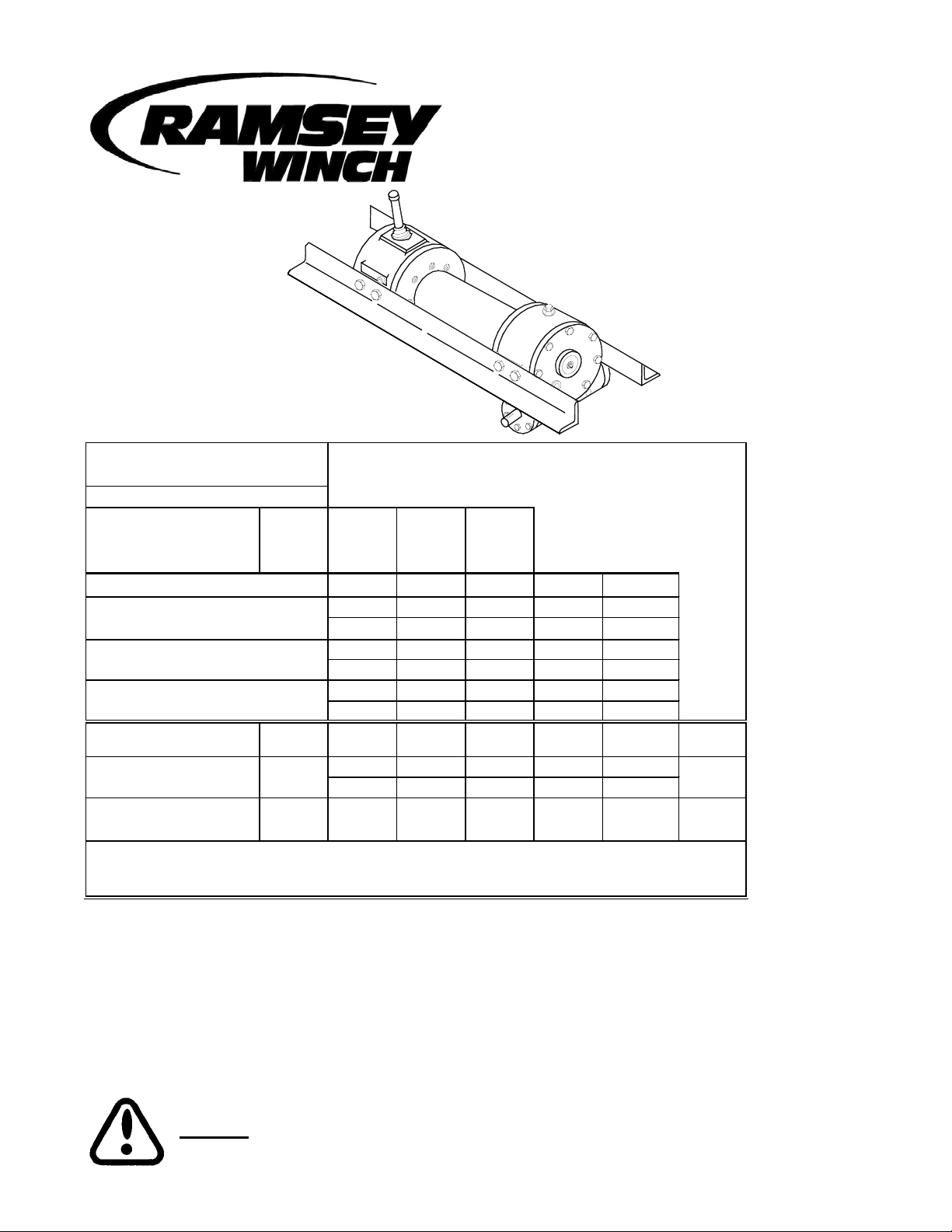
MODEL 800 / H-800 SERIES
DOW-LOK® EQUIPPED
INDUSTRIAL LOW-MOUNT WINCHES
Rated Line Pull (lbs.)
(kg)
Gear Reduction
Shipping Weight:
Layer of Cable
*Rated line pull per layer
*Cable Capacity
800 / H-800
*Cable Capacity
Y-800 / HY-800
*Line speed
800
H-800
* These specifications are based on recommended wire rope of .63 inch (16mm) diameter 6x19
extra improved plow steel cable
** Fifth layer does not conform to SAE J706
20,000
9,060
40:1
800 Y-800 H-800 HY-800
315 lbs.
(143 Kg)
(lbs.) 20,000 16,600 14,200 12,400 11,000
(kg) 9,060 7,510 6,430 5,610 4,980
(ft)* 35 75 125 180 240
(m)* 10 22 38 54 72
(ft)* 20 45 75 110 150
(m)* 6 13 22 33 45
FPM
MPM
FPM
MPM
290 lbs
(132 Kg)
330 lbs.
(150 Kg)
12345**
22 27 32 35 40
6.6 8.1 9.7 10.9 12.3
18 22 26 29 33
5.4 6.6 7.9 8.8 10.0
325 lbs.
(148 Kg)
Worm
RPM
570
460
30 GPM
Note: The rated line pulls shown are for the winch only. Consult wire rope
manufacturer for wire rope ratings
Congratulations
Ramsey Winches are designed and built to exacting specifications. Great care and skill go into every winch we make. If the
need should arise, warranty procedure is outlined on the back of your self-addressed postage paid warranty card. Please
read and fill out the enclosed warranty card and send it to Ramsey Winch Company. If you have any problems with your
winch, please follow instructions for prompt service on all warranty claims. Refer to back page for limited warranty.
CAUTION: READ AND UNDERSTAND THIS MANUAL BEFORE INSTALLATION AND OPERATION
OF WINCH. SEE WARNINGS!
1
Page 2

Page 3
Contents
Performance Specifications ...............................COVER
Safety Precautions...................................................... 1
Techniques of Operation ..........................................2-3
Winch Maintenance .................................................... 3
Winch Mounting ......................................................... 4
Cable Installation ........................................................4
Adjusting the Oil Cooled
Worm Brake ............................................................... 4
Servicing the Oil Cooled
Worm Brake ............................................................... 5
Re-assembling and
Checking the Brake.....................................................5
Test for Proper Brake Assembly.................................. 6
Instructions for Checking Assembly Arrangement
and Setting of Worm Brake ........................................6
Adjustment of Clutch Air Shifter ..................................7
Hydraulic System Requirements .................................8
Trouble Shooting Guide...............................................9
Instructions for Overhaul ..................................... 10-16
Disassembly....................................................... 10-13
Re-assembly ...................................................... 13-16
Dimensional Drawings
Model 800 / Y-800................................................17
Model H-800 / HY-800..........................................18
H-800 / HY-800 Short Coupling.............................19
H-800 / HY-800 Air Shifter ....................................20
HY-800 Short Coupling/Low Profile Shifter ............21
Parts List and Parts Drawing
Model 800 / Y-800.......................................... 22-23
Model H-800 / HY-800.................................... 24-25
H-800 / HY-800 SC......................................... 26-27
H-800 / HY-800 Air Shifter .............................. 38-29
Hy-800 Short Coupling/Low Profile Shifter....... 30-31
Warranty .................................................BACK COVER
Safety Precautions To Guard Against Possible Injury
A. Clutch must be totally engaged before starting the winch operation.
B. Do not disengage clutch under load.
C. Stay out from under and away from raised loads.
D. Stand clear of cable while pulling. Do not try to guide cable.
E. Do not exceed maximum line pull ratings shown in specifications.
F. Do not use winch to lift, support, or otherwise transport people.
G. A minimum of 5 wraps of cable around the drum barrel is necessary to hold load. Cable set screw is not
designed to hold load.
1
Page 4

Techniques of Operation
The best way to get acquainted with how your winch operates is to make test runs before you actually use it. Plan your test
in advance. Remember, you hear your winch, as well as see it operate. Get to recognize the sounds of a light steady pull,
a heavy pull, and sounds caused by load jerking or shifting. Gain confidence in operating your winch and its use will become second nature with you.
The uneven spooling of cable, while pulling a load, is not a problem, unless there is a cable pileup on one end of drum. If
this happens reverse the winch to relieve the load and move your anchor point further to the center of the vehicle. After the
job is done you can unspool and rewind for a neat lay of the cable.
The Dow-Lok® clutch provides free spooling and clutch engagement with the cable drum. With the clutch disengaged,
the cable can be freespooled off the drum. For winching in the load the clutch must be fully engaged with the drum.
®
The Dow-Lok
bottom of the shifter handle which fits into latching slots.
clutch is latched into either the engaged, “IN” position, or the disengaged “OUT” position, by a pin at the
TO UNLATCH CLUTCH
Run winch in the reverse (reel out) direction until the load is off the cable, Grasp handle firmly and while pushing
on the top of the handle with the thumb for leverage, lift until pin clears latching slots.
TO ENGAGE CLUTCH
Unlatch and pull handle toward “IN” position as far as it will go. In order to attain full engagement, internal elements
of the clutch must be aligned. This alignment will take place when the cable drum or cable drum shaft turns a
maximum of 1/4 revolution. The clutch will automatically spring into engagement and pin will drop into “IN” slots
when this alignment takes place. Do not attempt to lift a load unless pin is fully into “IN” slots. Keep clear of
spring-loaded handle during automatic engagement.
TO DISENGAGE CLUTCH
Unlatch and push handle to “OUT” position and fully insert pin into latching slots. Do not disengage the clutch
under load.
The Dow-Lok® air-shifter clutch provides free spooling and clutch engagement with the cable drum. With the clutch
disengaged, the cable can be freespooled off the drum. For winching in the load the clutch must be fully engaged with the
drum.
TO ENGAGE CLUTCH
There must be a minimum of 1 foot of slack in the cable before attempting to engage the clutch. This will allow the
drum to rotate a minimum of 1/4 turn allowing engagement of the clutch before picking up the load. With this slack
in the cable, exhaust air pressure from the air shift cylinder. Run the winch in the “IN” direction until the clutch
starts to turn. Clutch must be fully engaged before starting the winch operation.
TO DISENGAGE CLUTCH
Run winch in the “OUT” direction until there is no load on the cable. Apply 70-90 psi to the air shift cylinder to disengage the clutch. Do not disengage the clutch under load.
2
Page 5

The Dow-Lok® low-profile shifter clutch provides free spooling and clutch engagement with the cable drum. With the
clutch disengaged, the cable can be freespooled off the drum. For winching in the load the clutch must be fully engaged
with the drum.
TO ENGAGE CLUTCH
Raise the handle so the notch clears the bracket, and pull handle out as far as it will go. The clutch will automatically spring into engagement and latch when the clutch aligns with the drum shaft. In order to attain full engagement, internal elements of the clutch MUST be aligned. This alignment will take place when cable drum or cable
drum shaft turns a maximum of 1/4 revolution. Do not attempt to lift a load unless notch in shifter shaft is se-
curely latched. Keep clear of spring-loaded handle during automatic engagement.
TO DISENGAGE CLUTCH
Raise handle so notch clears bracket. Push handle in and latch the shaft notch onto bracket. Do not disengage the
clutch under load.
WINCH MAINTENANCE
Adhering to the following maintenance schedule will keep your winch in top condition and performing as it should with a
minimum of repair.
A. WEEKLY
1. Check the oil level and maintain it to the oil level plug. If oil is leaking out, determine location and repair.
2. Check the pressure relief plug in top of the gear housing. Be sure that it is in good operating condition so that hot oil
gasses may escape.
3. Lubricate cable with light oil.
B. MONTHLY
1. Lubricate the various grease fittings located in the ends of cable drum shaft, end bearing, clutch housing or clutch operating linkage. Any good grade of grease containing moly-disulfide is acceptable.
2. In the case of jaw clutch winches, check the action of the sliding clutch, making sure it is fully engaging and disengaging with the cable drum. Observe the jaws on both the clutch and cable drum, checking for rounding of the driving
faces. If rounding has occurred they should be replaced immediately.
3. In the case of Dow-Lok® clutches, check the action of the locking ring. Make sure it is spring loaded and free to move
fully against the cable drum in the engaged position and that it is pulled fully away from the cable drum and latched
when disengaged.
4. Check the winch mounting bolts. If any are missing, replace them and securely tighten any that are loose. Make sure
to use only grade 5 bolts or better.
5. Check the torque setting of the oil cooled worm brake. Make any adjustments required, following the procedure described in ADJUSTING THE OIL COOLED WORM BRAKE in the Owner's Manual.
6. Check alignment of chain and sprockets and adjust as required to minimize wear.
7. Inspect the cable. If the cable has become frayed with broken strands, replace immediately.
C. ANNUALLY
1. Drain the oil from the winch annually or more often if winch is used frequently.
2. Fill the winch to the oil level plug with clean kerosene. Run the winch a few minutes with no load in the reel in direction. Drain the kerosene from the winch.
3. Refill the winch to the oil level plug with all purpose E.P. 140 gear oil.
4. Inspect frame and surrounding structure for cracks or deformation.
5. Gear wear can be estimated by rocking the drum back and forth and if necessary drain oil and remove cover for closer
inspection.
3
Page 6

WINCH MOUNTING
It is most important that this winch be mounted securely so that the three major sections (the clutch housing end, the cable
drum and the gear-housing end) are properly aligned.
All standard H-800 Dow-Lok® series winches are furnished with recommended mounting angles. Angle size is 1/2 x 3 x 4
high strength steel angle.
CABLE INSTALLATION
The Ramsey Model H-800 "Dow-Lok"® winch has two tapered pockets cast into the drum. One pocket is for installations
with the wire rope wound over the drum. The other pocket is for an underwound wire rope.
1. Slide the wire rope through narrow end of the pocket against the drum flange.
2. Wrap the wire rope around the anchor "puck" and pull the wire rope and anchor back into the wide end of the pocket.
3. Use a soft hammer to drive the back side of the wire rope, firmly seating the wire rope and anchor, into the pocket.
The wire rope can easily be removed from the drum by driving the anchor out the wide end of the pocket.
The Ramsey Model Y-800/HY-800 ("Y" drum) "Dow-Lok"® winch has a setscrew to secure cable to drum.
Insert the end of cable, opposite hook end, into the 11/16" dia. hole in drum barrel. Secure cable to drum barrel, using setscrew furnished with winch. TIGHTEN SETSCREW SECURELY.
Carefully run the winch in the "reel-in" direction, keeping tension on end of cable, spool all the cable onto the cable drum,
taking care to form neatly wrapped layers.
ADJUSTING THE OIL COOLED WORM BRAKE
The oil cooled, fully adjustable, automatic worm brake operates in the worm housing lubricant, all parts being submerged in
oil. When the brake wears to the point that the load begins to drift, the brake can be adjusted as follows:
1. Loosen the adjusting screw lock nut.
2. Tighten the brake by turning the adjusting screw clockwise. CAUTION: Only 1/4 turn is usually required to adjust the
brake. Over-tightening can cause over-heating, and damage to the brake parts. Tighten the lock nut after adjustment is
completed.
If the brake does not respond to adjustment then a new leaf spring and brake disc is needed.
A torque wrench can be equipped with a special adapter to fit the input shaft (worm) of the winch. The adapter can be
made by welding a nut to the end of a piece of tubing as shown in the following figure.
After welding the cap and nut to the tubing, slot the
tubing, as shown. This will allow the special adapter
to slide over the keyway and will then act as a large
socket. A torque wrench can the be used to apply the
proper torque. Turn the torque wrench so that the
drum turns in the spool out direction or lowering direction. The torque rating for the brake on the Model H800 Dow-Lok® should be 50 to 55 ft-lbs. If torque
wrench does not show the proper value as it turns,
then the worm brake adjusting bolt should be turned
clockwise 1/4 turn. Each time the adjusting bolt is
turned, check the torque reading. Continue this procedure until the proper torque reading is achieved. Then
tighten the lock nut.
CAP
NUT
TUBING
ADAPTER
SOCKET
4
Page 7

BRAKE HOUSING
HUB
A
CAM PLATE
RETAINER PLATE
GASKET
THREAD SEAL
JAM NUT
ADJUSTING
SCREW
COVER
MOUNTING
SCREW
PIN
BRAKE COVER
DIAGRAM 1
BALL
COMPOSITION
BRAKE DISC
LEAF SPRING
COIL SPRING
PLATE FROM WINCH)
WORM BRAKE
SERVICING OF THE OIL COOLED SAFETY BRAKE
1. Remove the drain plug and drain the worm gear oil from the worm housing.
A
2
1
2
1
VIEW
(LOOKING AT CAM
A-A
2. Back off the lock nut, then the adjusting screw, both two turns or more by turning them counter-clockwise.
3. Remove the cover mounting screws.
4. Remove the cover along with coil spring and leaf spring.
5. Remove the retainer plate, composition brake disc, cam plate and balls. Note which slots balls are in.
6. Inspect parts as follows:
a) Composition brake discs are 1/4" thick when new. Replace if thinner than 3/16 or if surfaces are glazed or burnt.
b) Inspect the flat, ground surface of the cam plate and retainer plate for glazing, warpage, or other damage. Glazing
can be removed by scraping carefully.
c) Inspect the leaf spring. It should be bowed 1/8".
RE-ASSEMBLING AND CHECKING THE BRAKE
1. Press brake hub into place over worm shaft and key.
2. Assemble balls in appropriate slots of cam. Use stiff grease to hold balls into place and slide cam over end of worm.
Be sure that balls are secure, between cam slots and hub slots. See instructions at right to determine proper ball slot
setting. Install brake disc.
3. Install retainer plate, smooth side toward brake disc.
4. Install the gasket on the cover with a small amount of grease or sealer.
5. The coil spring goes over the adjusting screw on the inside of the cover.
6. Install the notches of the leaf spring on the pins protruding through the cover. The hollow side of the leaf spring goes
toward the brake.
7. Install brake housing cover, making sure the protruding pins go through the leaf spring and into the holes in the retainer
plate.
8. Bolt cover into place with the mounting screws. Install drain plug and add 3-3/4 pints all purpose E.P. 140 oil.
9. Turn winch in the hoisting direction at least one turn of the input shaft.
10. Turn the adjusting screw in until it is finger tight.
5
Page 8

TEST FOR PROPER BRAKE ASSEMBLY
After the brake has been adjusted to the proper torque setting disengage clutch. Start vehicle engine and run winch in the
reel in (hoisting direction). Allow winch to run in this direction for one minute.
Place your hand on the safety brake housing. If housing is not hot to the touch then run winch in the reverse direction
(cable out) for one minute. Brake housing should begin to heat.
When these conditions exist, proper installation has been made. If heating becomes noticeable when running the winch in
forward rotation (hoisting direction), the brake should be again disassembled. When disassembled, place the brake balls in
the alternate set of slots in the cam plates, then carefully follow the instructions for re-assembling and checking the brake.
INSTRUCTIONS FOR CHECKING ASSEMBLY ARRANGEMENT AND SETTING OF WORM
BRAKE
When the worm brake is assembled the brake must be set with the balls in the #1 or the #2 set of cam slots. (See View AA, page 6). It is indicated on the name plate whether the balls were installed in the #1 or the #2 slots at the factory.
Three factors determine which slots the balls should be in:
1. Direction cable winds on the drum. It normally winds over the top of the drum barrel.
2. The cut of the gear set, right or left gear. The last letter in the model number of the winch, either R or L, designates right
or left gear set. Example: R-20AR, R-30L, 700R, 800L.
3. The side of the winch that the input shaft is on. The Input Shaft is normally toward the cab. Whether the winch has a
gear box on the right or the left side of the winch does not affect the brake setting.
When cable winds over the top of the drum, winch has a right cut gear and input shaft is toward the cab, then the balls
need to be in the #2 cam slots.
If any one of these three factors differ from those stated above, the balls need to be in the #1 slots in the cam. A second
change in these factors requires the original arrangement, and if all three factors are different, the balls need to be in the #1
slots.
6
Page 9
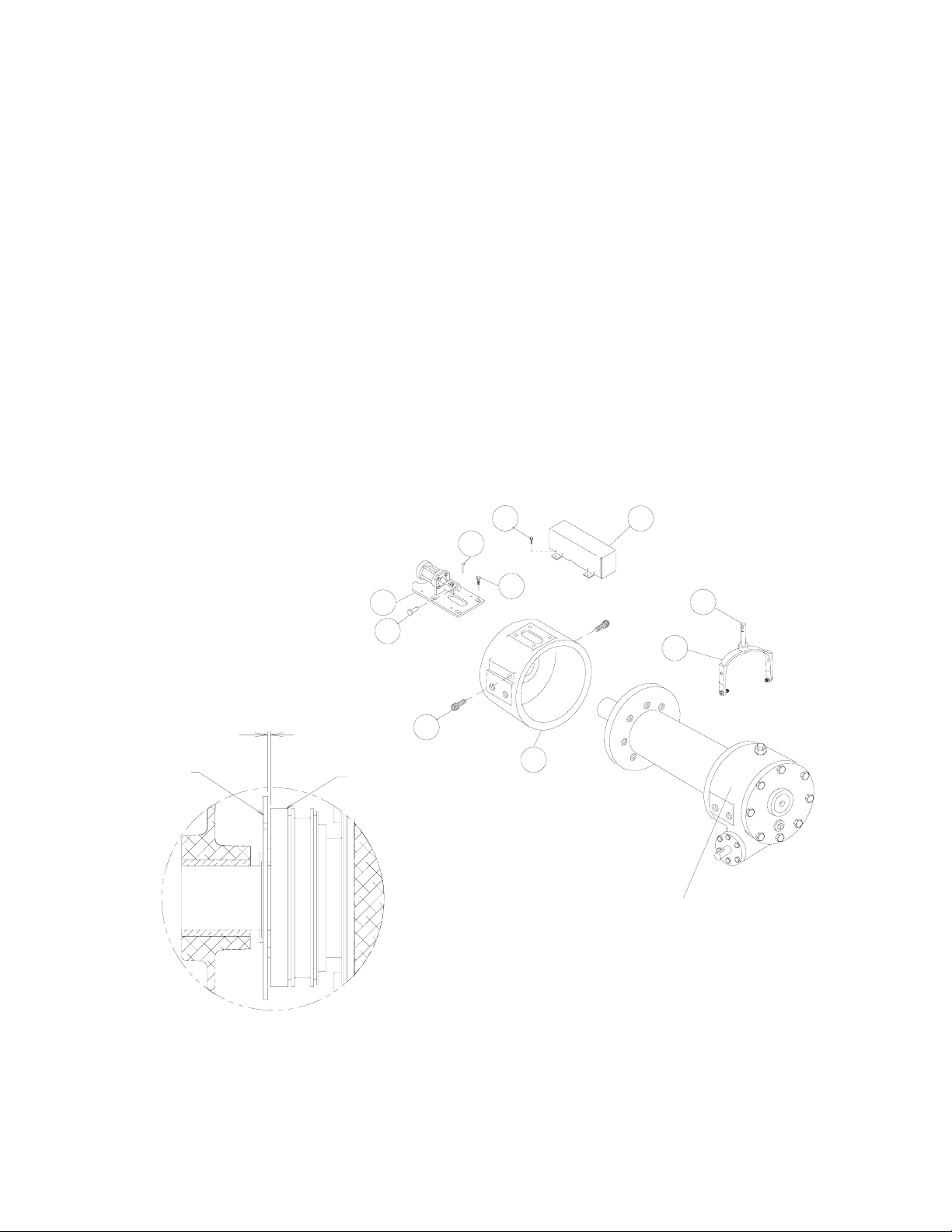
ADJUSTMENT OF CLUTCH AIR SHIFTER
1. Place winch assembly back into mounting frame and
reattach using (8) mounting bolts and lockwashers.
Torque mounting hardware to 290 ft. lbs. each. Make
sure that gear housing and clutch housing are not rubbing against drum flanges.
2. Place air shifter assembly #5 over shifter shaft aligning
clevis over flats of shaft. Secure clevis to shaft using
clevis pin #76 and cotter pin #75. Place shifter shaft in
the "ENGAGED" position. With the air cylinder shaft fully
retracted, push shifter assembly toward the drum until
all play is taken out of the shifter shaft. Secure shifter
assembly to clutch housing using (4) capscrews #46
(flanged hx. hd. serrated). Tighten securely, but do not
torque.
61
3. Hook up air (70 to 90 psi) to inlet port of air cylinder and
disengage clutch. Look into the opening in the clutch
housing and verify that the locking ring and retainer plate
are not making contact. Locking ring and retainer plate
must not make contact. There must be a clearance
(gap) of .09 inch (max.) between the locking ring and
retainer plate when the winch is fully disengaged. If
there is contact, the (4) capscrews #46 should be loosened and the plate pulled away from the drum approximately .06 inch. Tighten screws securely and check
action to assure needed clearance. Repeat adjustment
procedure as needed to acquire needed gap. Shift
clutch 2 or 3 times to verify proper shifting of clutch.
After final adjustment, torque (4) capscrews #46 to 18
ft. lbs. each. Attach cover #43 using (4) capscrews
#61.
61
43
RETAINER
PLATE
.09 MAX.
1
76
LOCKING
RING
39
34
37
53
21
WINCH ASSEMBLY
7
Page 10
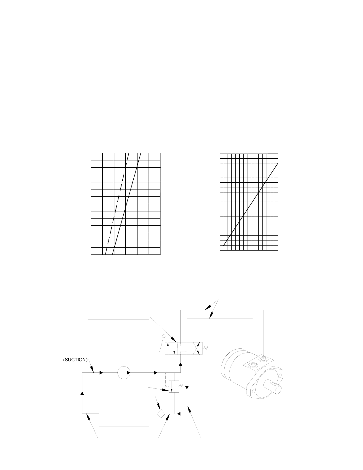
HYDRAULIC SYSTEM REQUIREMENTS
Refer to the performance charts, below, to properly match your hydraulic system to H-800 Dow-Lok® winch performance.
The charts consist of :
(1) Line pull (lb.) first layer vs. working pressure (PSI). STATIC (solid line) refers to hoisting a suspended load from rest;
DYNAMIC (dotted line) refers to maintaining the motion of a moving load.
(2) Line speed, first layer (FPM) vs. Flow, gallons per minute (GPM).
Performance based on a motor displacement of 14.9 cubic inches with 30 GPM maximum flow rate. See page 18 for motor port size.
H-800, HY-800 Series Performance
20,000 lb. Duty Rating 40:1 Gear Ratio
20,000
18,000
16,000
14,000
12,000
10,000
8,000
LINE PULL, LBS., FIRST LAYER
6,000
0
WORKING PRESSURE, PSI
N
Y
D
TYPICAL HYDRAULIC LAYOUT
CONTROL VALVE
3 POSITION 4 WAY
CYLINDER SPOOL
20
C
I
M
C
I
A
T
A
T
S
30001000 2000
15
10
5
LINE SPEED, FPM, FIRST LAYER
0
0
10 20 30
FLOW, GPM
HIGH PRESSURE LINES
(.88 I.D. MINIMUM)
PUMP INLET LINE
PUMP
RELIEF VALVE
FLUID FILTER
FLUID
RESERVOIR
LOW PRESSURE LINES
HYDRAULIC
WINCH MOTOR
LOW PRESSURE LINES
(1.31 I.D. MINIMUM)
8
Page 11

TROUBLESHOOTING GUIDE
CONDITIONS POSSIBLE CAUSE CORRECTION
CLUTCH INOPERATIVE OR BINDS UP 1. Dry or rusted shaft. 1. Clean and Lubricate.
2. Bent yoke or linkage 2. Replace yoke or shaft assembly.
CLUTCH HANDLE WON’T LATCH 1. Debris in clutch. 1. Clean and lube per page 15.
OIL LEAKS FROM HOUSING 1. Seal damaged or worn. 1. Replace seal.
2. Too much oil.
3. Damaged gasket. 3. Replace gasket.
LOAD DRIFTS DOWN 1. Worm brake has become worn. 1. Replace brake disc. (See page 6)
2. Worm brake out of adjustment.
WINCH RUNS TOO SLOW 1. Hydraulic motor worn out. 1. Replace motor.
2. Low flow rate.
CABLE DRUM WILL NOT FREESPOOL
CABLE BIRDNESTS WHEN CLUTCH IS
DISENGAGED
1. Winch not mounted squarely, causing end bearings to bind drum.
1. Drag brake disc worn. 1. Replace discs.
2. Drain excess oil. Refer to Techniques of Operation.
2. Turn adjusting bolt clockwise 1/4
turn or until load does not drift.
2. Check flow rate. Refer to Hydraulic
Systems flow chart, page 8.
1. Check mounting. Refer to Winch
Mounting, page 5.
HYDRAULIC FLUID LEAKS FROM
HOLE IN ADAPTER
1. Damaged motor shaft seal. 1. Replace seal.
9
Page 12

INSTRUCTIONS FOR OVERHAUL OF RAMSEY MODEL H-800 DOW-LOK®
Dis-assembly
Refer to parts list and parts drawing pages for actual item numbers and corresponding parts numbers.
(1)
Drain oil from gear housing by removing pipe plug (item #63)
from gear housing.
Shift clutch into the engaged "IN" position.
Remove frame angles (item #2) from winch assembly.
2
2
48 55
19 37
73
46
(3)
Slide the locking ring (item #10) from the clutch. NOTE: The
locking ring cannot be removed unless the clutch is engaged, with
dowel pins (item #65) seated in the shaft keyways.
Rotate the drum so the eight balls (item #33) and four dowel pins
(item #65) can be removed.
If necessary, the clutch (item #9) may be disassembled from the
drum by removing eight capscrews (item #43). Slide drum (item
#14) from drum shaft.
70
67
29
(2)
Remove two capscrews (item #46) from clutch housing (item #19)
and unlatch shifter assembly.
Remove clutch housing from end of drum shaft. Press in on retainer
plate (item #67), to relieve the spring tension and remove the retainer ring (item #70).
Remove four capscrews (item #37), retainer plate (item #67),
springs (item #73) and spacer (item #29).
47
10
55
33
63
9
43
65
14
65
41
13
52
68
72
24
76
(4)
Remove key (item #24) from worm shaft.
Remove bearing cap (item #8) and gasket (item #56) by unscrewing six capscrews (item #41) and lockwashers (item 52).
Remove seal (item #68) from bearing cap and press new seal
into place.
Drag brake disc (item #13), spacer (item #76) and spring (item
#72) should be examined and replaced if necessary.
56
8
10
Page 13

(5)
Remove motor (item #62) from adapter plate (item #26) by
removing capscrews (item #51). Remove adapter plate and
coupling (item #2) from adapter (item #3) by unscrewing
eight capscrews (item #48).
Remove key (item #24) from worm shaft. Unscrew six capscrews (item #50) and remove adapter from gear housing.
Replace adapter seal (item #70) and gasket (item #57).
(5a)
62
51
26
48
50
24
70
3
2
34
57
32
54
47
48
59
68
(6)
Refer to page 5, SERVICING OIL COOLED SAFETY BRAKE. Remove brake housing (item #18) from gear housing by unscrewing six (item #49) capscrews. Remove key (item #23) from
worm. Remove worm (item #30) and bearings (item #34) from
gear housing. Use a soft hammer to gently tap input end of
worm and drive worm and bearing from gear housing. Once
worm has been removed from housing, bearing can be pressed
from end of worm.
Check for signs of wear or damage to worm (item #30) and
bearings (item #34). Replace if necessary.
2
28
74
Remove motor (item #59) from adapter (item #2) by removing
two capscrews and lockwashers (item #48 & #52). Remove
adapter (item #2) from gear housing by removing six (item #47)
capscrews. Replace pilot seal (item #68) and gasket (item #54).
Remove thrust bearing (item #32) and thrust washers (item #74).
34
49
23
30
18
56
34
(7)
Remove gear housing cover (item #12) from gear housing
(item #20) by unscrewing eight capscrews (item #40).
Thread two of the capscrews into the two tapped holes of
cover and tighten. This will pull the cover loose from gear
housing.
Remove cover gasket (item #58) and pull shaft (item #27),
with gear (item #17) and spacer (item #74) attached, from
gear housing.
20
27
74
17
12
40
58
11
Page 14

78
62
27
22
62
78
17
54
45
(9)
If shaft and/or gear hub is damaged, replace as follows:
a. Tap keys (item #25) into short keyways of drum shaft
(item #27).
b. Press shaft (item #27) and keys through gear hub (item
#17) until end of keys on long end of shaft are flush with
hub.
(8)
Check for signs of wear on gear teeth. If necessary, replace
gear.
Check lube fittings (item #78) for damage and replace if necessary. Remove lube fittings (item #78) and reducers (item
#62) from ends of shaft, if following Step 9, and reinstall
after Step 9.
25
17
27
(10)
Check gear housing bushing (item #5) and o-ring (item #63) for signs of
wear. Replace if necessary by pressing old bushing from gear housing (item
5
20
(11)
Check drum bushings (items #35 & #36) for signs of
wear. Replace if necessary by pressing old bushings from
drum (item #14). Press bushing (item #35) into bore in
drum until it's flange is seated against bottom of counterbore. Press bushing (item #36) into opposite bore on
drum until end of bushing extends .50" from end of drum.
61
#20). Press new bushing into place and insert new o-ring (item #61) into
groove inside of bushing.
25
14
36
35
12
Page 15

19
(12)
36
(13)
Check cover bushing (item #5) and o-ring (item #61) for signs of wear. Replace if
necessary by pressing old bushing from gear housing cover (item #12). Press new
bushing into place and insert new o-ring (item #61) into groove inside of bushing.
Check end bearing bushing (item #36) for signs of wear. If necessary, remove old bushing
and press new bushing into place.
RE-ASSEMBLY
(14)
Slide spacer (item #74) over long end of shaft and place
against gear hub. Apply grease to end of shaft, opposite
gear. Apply grease to bushing in gear housing (item #20).
Place greased end of shaft through bushing in gear housing
(item #20). Place gasket (item #58) onto gear housing
cover (item #12). Apply grease to gear end of shaft and
cover bushing. Place cover onto shaft and secure to housing with eight (item #40) capscrews. Tighten capscrews
40
to 39 ft. lb. (52 Nm.) each.
20
74
27
17
58
12
5
12
61
(15)
Press bearing (item #34) onto worm (item #30).
NOTE: Be sure that thick shoulder of bearings outer
race (side with manufacturer's name and part number) is
out, away from worm threads. Press bearing and worm
into gear housing. Slip gasket (item #56) onto brake
housing (item #18). Use six capscrews (item #49) to
secure brake housing to gear housing. Tighten capscrews to 45 ft. lb. (61 Nm.) each.
Place key (item #23) into keyway of worm (item #30).
Refer to page 6 for reassembly and checking of worm
brake.
49
23
30
18
56
34
13
Page 16

(16)
Press bearing (item #34) onto worm and into housing. NOTE:
Be sure that thick shoulder of bearings outer race (side with
manufacturer's name and part number) is out, away from worm
threads. Attach bearing cap (item #8) to gear housing using six
capscrews (item #41) with lockwashers (item #52). Tighten
capscrews to 39 ft. lb. (52 Nm.) each. Insert key (item #24) into
keyway of worm shaft.
24
52
(17)
Press bearing (item #34) onto worm and into housing. NOTE:
Be sure that thick shoulder of bearings outer race (side with
manufacturer's name and part number) is out, away from
worm threads. Attach adapter (item #3) to gear housing using
six capscrews (item #50). Tighten capscrews to 45 ft. lb. (61
Nm.) each. Insert key (item #24) into keyway of worm shaft.
Slide coupling (item #2) over end of worm shaft. Attach
adapter plate (item #26) to adapter using eight capscrews
(item #48). Tighten capscrews to 21 ft. lb. (28 Nm.) each.
Place motor shaft, with key in keyway, into coupling. Secure
motor (item #62) to adapter, using two capscrews (item
#51). Tighten capscrews to 102 ft. lb. (138 Nm.) each.
62
51
26
48
50
24
34
57
3
2
41
34
56
8
(17a)
Place thrust washers (item #74) and thrust bearing (item
#32) over end of worm (item #28) and into housing.
Attach adapter (item #2) with gasket (item #54) to housing, using six (item #47) capscrews. Tighten capscrews
to 45 ft.lb. (61Nm.) each.
Insert pilot seal (item #68) into adapter and carefully place
motor shaft, with key in keyway, through seal, so as not
to damage seal. Insert motor shaft into end of worm (item
#28). Secure motor (item #59) to coupling using two
(item #48) capscrews with lockwashers (item #52).
Tighten capscrews to 102 ft.lbs. (138 Nm.) each.
59
48
47
2
74
28
32
54
68
14
Page 17

(18)
Place winch with gear housing cover down on work bench. Drum shaft should be in vertical position. Set springs (item #72) into pockets of gear housing with drag brakes (item #13) on top
of disc (item #76) and springs. Slide drum assembly (item #14) onto drum shaft as shown.
14
13
76
10
9
43
(19)
Place clutch (item #9) over end of drum
72
shaft. Align the clutch over the pilot
65
bushing in drum. Install the eight capscrews (item #43) and torque the capscrews to 103 ft. lb. (139 Nm.) to securely seat the clutch to the
drum.
33
14
Rotate the drum to align the clutch slots with the shaft keyways.
Lightly grease four dowel pins (item #65) and eight balls (item
#33). Use molybdenum disulfide or graphite bearing grease. In-
65
sert the four dowel pins (item #65) and eight balls (item #33). In
the engaged position the balls are nearly flush with the clutch.
Lightly grease the internal and external groove and bore in locking
ring (item #10) and clutch (item #9).
Slide locking ring onto the clutch. When fully engaged, the locking ring touches the clutch flange and there is .71 to .73
inches between the end of the locking ring and the end of the clutch.
(20)
Place four springs (item #73) over four roll pins on
retainer plate (item #67). Install spacer (item #29)
and retainer plate and secure to clutch using four capscrews (item #37). Tighten capscrews to 9.7 ft. lb.
(13 Nm.) each. Firmly seat the retainer ring (item #70)
into drum shaft groove.
Set the shifter assembly so that the screw heads engage the external groove in the locking ring (item #10).
Push the clutch housing (item #19) onto the drum
shaft and latch the shifter assembly in the engaged "IN"
position. Insert the two capscrews (item #46).
46
39
1
1
37
73
19
70
67
29
15
Page 18

(21)
Attach mounting angles (item #2) to winch assembly. Use
2
55
48
capscrews (item #47 & #48) and lockwashers (item #55).
Tighten capscrews to 290 ft. lb. (393 Nm) each. Insert plug
(item #63) into hole in bottom of gear housing. Remove
2
59
62
plugs (items #59 & 62) from top of housing. Pour 3 -3/4
pints of E.P. 140 oil into hole and replace plugs.
Check the action of the clutch by shifting and freespooling the
winch drum several times.
The shift pattern plate on top of the clutch housing is adjusted
47
55
63
at the factory to provide reliable shifting of the Dow-Lok®
clutch. If the plate should loosen or be removed, you must
readjust the plate. Shift the handle to disengage the clutch and hold against the internal stop. With the latching pin in the
"OUT" slots, push the shift pattern plate toward the cable drum. Unsnap plastic lever cover from pattern plate. Tighten the
four capscrews which hold the plate to housing. Snap lever cover back into place around the pattern plate.
16
Page 19

MM
INCHES
EF
MM
INCHES
D
MM
INCHES
MM
INCHES
5.69
144,5
53,0
2.09
492,2
19.38
273,0
10.75
5.50
139,7
50,8
2.00
346,2
13.63
347,4
13.68
9.18
6.18
233,1
156,9
355,6
14.00
.50
3.00
76,2
5.15
130,8
12,7
DIA.
1.25
31,7
.31 x .15 x 2.0 LG.
1.87
KEYWAY
47,5
8.43
214,3
263,6
10.38
E
3.50
88,9
6.87
174,6
72,1
2.84
7.75
196,8
DIMENSIONS SHOWN ARE INCHES OVER MILLIMETERS
BC
INCHES
A
INCHES
WINCH
MM
MM
MODEL
381,0
15.00
10.62
269,7
800
9.44
7.75
Y-800
239,8
196,8
®
HANDLE SPRING LOADED
IN THIS DIRECTION
A
DIS-ENGAGED
CLUTCH
ENGAGED
CLUTCH
2.50
63,5
31,7
1.25
B
308,0
Ø12.13
F
DIA.
46.00
1166,4
D
CLUTCH HOUSING CAN BE
CUSTOMER INSTALLATION
ROTATED 180° FOR
2.50
63,5
C
2.40
61,0
Model 800 Dow-lok
800 / Y-800
17
Page 20

MM
INCHES
EF
MM
INCHES
D
MM
INCHES
5.69
144,5
52.00
1320,8
492,2
19.38
5.50
139,7
46.00
1168,4
346,2
13.63
9.18
6.18
233,1
156,9
.94
5.15
23,8
130,8
57,1
2.25
2-PLACES 180° APART
57,1
2.25
1-1/16-20 O-RING PORT
6.54
166,1
284,4
11.20
263,6
10.38
8.36
212,3
DIMENSIONS SHOWN ARE INCHES OVER MILLIMETERS
355,6
14.00
.50
12,7
3.00
76,2
2.13
54,0
®
MM
13.81
INCHES
BC
MM
15.00
INCHES
A
MM
10.62
INCHES
WINCH
MODEL
350,7
381,0
269,7
H-800
13.68
9.44
7.75
HY-800
347,4
239,8
196,8
HANDLE SPRING LOADED
IN THIS DIRECTION
CLUTCH
4.00
101,6
8.40
213,3
6.87
174,6
72,1
2.84
A
B
7.75
196,8
2.50
63,5
31,7
1.25
F
DIA.
E
D
308,0
Ø12.13
DIS-ENGAGED
CLUTCH HOUSING CAN BE
CUSTOMER INSTALLATION
ROTATED 180° FOR
Model 800 Dow-lok
H-800 / HY-800
CLUTCH
ENGAGED
18
2.40
2.50
63,5
C
61,0
Page 21

FE
INCHES
INCHES
D
INCHES
CB
INCHES
INCHES
MM
MM
MM
MM
MM
5.69
144,5
52.00
1320,8
19.38
492,2
13.81
350,7
15.00
381,0
5.50
139,7
46.00
1168,4
13.63
346,2
13.68
347,4
9.44
239,8
355,6
14.00
.50
12,7
3.00
76,2
9.18
233,1
6.18
156,9
2.13
54,0
6.87
174,6
72,1
2.84
5.15
130,8
57,1
2.25
57,1
2.25
.94
23,8
4.00
101,6
7.75
196,8
2-PLACES 180° APART
1-1/16-20 O-RING PORT
8.36
6.54
6.41
10.38
212,3
166,1
162,8
263,6
DIMENSIONS SHOWN ARE INCHES OVER MILLIMETERS
A
MM
269,7
10.62
INCHES
WINCH
H-800
MODEL
®
Model 800 Dow-lok
H-800 / HY-800 SHORT COUPLING
7.75
196,8
HY-800
HANDLE SPRING LOADED
IN THIS DIRECTION
CLUTCH
CLUTCH
2.50
63,5
31,7
A
B
F
1.25
DIA.
E
D
308,0
Ø12.13
DIS-ENGAGED
CLUTCH HOUSING CAN BE
CUSTOMER INSTALLATION
ROTATED 180° FOR
2.50
63,5
C
2.40
61,0
ENGAGED
19
Page 22

9.18
6.18
8.91
226,0
.50
12,7
3.00
233,1
156,9
76,2
2.13
54,0
5.15
130,8
57,1
2.25
57,1
2.25
.94
23,8
4.00
101,6
6.54
11.20
10.38
2-PLACES 180° APART
1-1/16-20 O-RING PORT
166,1
284,4
263,6
8.36
212,3
DIMENSIONS SHOWN ARE INCHES OVER MILLIMETERS
®
FE
INCHES
INCHES
D
INCHES
CB
INCHES
INCHES
A
INCHES
WINCH
MM
MM
MM
MM
MM
MM
MODEL
8.40
213,3
5.69
5.50
144,5
139,7
72,1
2.84
46.00
52.00
1168,4
1320,8
19.38
492,2
13.63
346,2
13.68
347,4
13.81
350,7
A
6.87
174,6
B
9.44
15.00
381,0
239,8
7.75
196,8
269,7
10.62
308,0
Ø12.13
H-800
HY-800
7.75
196,8
2.50
63,5
31,7
1.25
F
DIA.
D
E
2.50
63,5
C
2.40
61,0
3.13
79,3
Model 800 Dow-lok
H-800 / HY-800 AIR SHIFTER
20
1/8-27NPT PORT
(70 PSI MIN. PRESSURE)
(90 PSI MAX. PRESSURE)
FOR DISENGAGING CLUTCH
CLUTCH IS SPRING ENGAGED
Page 23

5.15
130,8
57,1
2.25
2-PLACES 180° APART
57,1
2.25
8.13
206,5
.94
23,8
3.00
76,2
9.18
233,2
6.18
156,9
1-1/16-20 O-RING PORT
8.36
212,3
6.54
166,1
6.47
164,3
263,6
10.38
.50
12,7
88,9
3.50
6.87
174,6
72,1
2.84
270,5
10.65
7.81
198,4
9.41
239,0
598,9
23.58
308,0
Ø12.13
7.75
196,8
2.50
63,5
31,7
1.25
Ø5 .5 0
139,7
351,0
13.82
DIMENSIONS SHOWN ARE INCHES OVER MILLIMETERS
46.00
1168,4
®
Model 800 Dow-lok
H-800 / HY-800 SHORT COUPLING LOW-PROFILE SHIFTER
ENGAGED
328,4
12.93
2.50
DISENGAGED
2.40
61,0
46,2
1.82
8.13
206,5
63,5
21
Page 24

22 23
Page 25

PARTS LIST MODEL 800 DOW-LOK®
61 2 462013 QUAD-RING
Item No. Qty. Parts No. Description Item No. Qty. Parts No. Description
1 1 276033 SHIFTER ASSEMBLY 40 8 414277 CAPSCREW 3/8-16NC X 1 LG HX HD GR5 NYLOK HVY P
2 2 302093 ANGLE - Y800 41 6 414282 CAPSCREW 3/8-16NC X 1-1/4 LG HX HD DR5
3 2 302111 ANGLE - STD. 42 2 414399 CAPSCREW 3/8-24NF X 1-1/4 LG ALL-THRD GR5
4 1 306035 SPRING - FLAT 43 8 414571 CAPSCREW 1/2-20NF X 1 LG HX HD GR5
5 2 308083 BUSHING 44 1 414603 CAPSCREW 1/2-20NF X 1-3/4 LG ALL-THRD GR5
6 1 314007 CAM PLATE
7 1 314010 CABLE ANCHOR ("STD." DRUM ONLY 46 2 414619 CAPSCREW 1/2-13NC X 2-1/2 LG HX HD ALL-THRD ZP
8 1 316006 CAP BEARING 47 4 414751 CAPSCREW 3/4-10NC X 1-3/4 GR5 NYLOK HVY PATCH
9 1 324151 CLUTCH 48 4 414777 CAPSCREW 3/4-10NC X 1-3/4 GR5
10 1 324318 LOCKING RING 49 6 414897 CAPSCREW 3/8-16NC X 1 LG SOC HD
11 1 328027 COVER - BRAKE 50 1 418067 NUT 1/2-20NF HX JAM
12 1 328122 COVER - GEAR HOUSING 51 4 418163 LOCKWASHER 5/16 MED SECT PLTD
13 2 330010 SHOE - DRAG BRAKE 52 6 418177 LOCKWASHER 3/8 MED SECT PLTD
14 1 332167 DRUM (STANDARD) 53 4 418184 WASHER - FLAT 3/8 ALUM
15 1 332172 DRUM ("Y" 800)
16 1 334189 GEAR - L.H. 55 8 418249 LOCKWASHER 3/4 MED SECT
17 1 334188 GEAR - R.H. 56 2 442192 GASKET
18 1 338221 HOUSING - BRAKE 57 1 442194 GASKET
19 1 338235 HOUSING - CLUTCH 58 1 442195 GASKET
20 1 338242 HOUSING - GEAR 59 1 456008 FITTING - RELIEF
21 1 340011 HUB - BRAKE 60 1 456031 FITTING - LUBE
23 1 342053 KEY 62 3 468002 REDUCER
24 1 342092 KEY 63 2 468011 PIPE PLUG
25 2 342153 KEY 64 4 470042 PIN - ROLL
26 1 352021 PLATE - RETAINER 65 4 470044 PIN - DOWEL
27 1 357498 SHAFT - DRUM (STD.) 66 4 470056 PIN - ROLL
28 1 357502 SHAFT - DRUM (Y800) 67 1 474030 PLATE - RETAINER
29 1 362224 SPACER 68 1 486068 SEAL - OIL
30 1 368082 WORM R.H. 69 1 486076 THREAD SEAL
31 1 368084 WORM L.H. 70 1 490025 RING - RETAINER
32 2 400007 BALL - BRAKE 71 1 494010 SPRING
33 8 400011 BALL - CLUTCH 72 2 494022 SPRING - DISC
34 2 402045 BEARING - BALL 73 4 494069 SPRING
35 1 412051 BUSHING 74 1 518016 THRUST WASHER
36 2 412052 BUSHING 75 1 530007 DISC - BRAKE
37 4 414038 CAPSCREW 1/4-20NC X 3/4 LG HX HD GR5 76 2 530094 SPACER - BRAKE
38 4 414069 CAPSCREW 5/16-18NC X 3/4 LG HX HD 77 1 416059 SETSCREW ("Y" DRUM ONLY)
39 4 414111 CAPSCREW 5/15-18NC X 1 LG HX HD GR5 78 2 456039 LUBE FITTING
Page 26

24 25
Page 27

PARTS LIST MODEL H-800 DOW-LOK®
62 1 458048 MOTOR - HYD
80 2 456039 LUBE FITTING
1 1 276033 SHIFTER ASSEMBLY 40 8 414277 CAPSCREW 3/8-16NC X 1 LG HX HD GR5 NYLOK HVY P
2 1 299733 COUPLING ASSEMBLY 41 2 414399 CAPSCREW 3/8-24NF X 1-1/4 LG ALL-THRD GR5
3 1 300048 ADAPTER 42 8 414571 CAPSCREW 1/2-20NF X 1 LG HX HD GR5
4 2 302710 ANGLE - Y800 43 1 414603 CAPSCREW 1/2-20NF X 1-3/4 LG ALL-THRD GR5
5 2 302711 ANGLE - STD.
6 1 306035 SPRING - FLAT 45 2 414619 CAPSCREW 1/2-13NC X 2-1/2 LG HX HD ALL-THRD ZP
7 2 308083 BUSHING 46 4 414751 CAPSCREW 3/4-10NC X 1-3/4 GR5 NYLOK HVY PATCH
8 1 314007 CAM PLATE 47 4 414777 CAPSCREW 3/4-10NC X 1-3/4 GR5
9 1 314010 CABLE ANCHOR ("STD." DRUM ONLY) 48 8 414871 CAPSCREW 5/16-18NC X 1-1/4 LG SOC HD LOK-WEL
10 1 324151 CLUTCH 49 6 414897 CAPSCREW 3/8-16NC X 1 LG SOC HD
11 1 324318 LOCKING RING 50 6 414909 CAPSCREW 3/8-16NC X 1-3/4 LG SOC HD LOK-WEL
12 1 328027 COVER - BRAKE 51 2 414950 CAPSCREW 1/2-13NC X 1-3/4 LG SOC HD LOK-WEL
13 1 328122 COVER - GEAR HOUSING 52 1 418067 NUT 1/2-20NF HX JAM
14 2 330010 SHOE - DRAG BRAKE 53 4 418163 LOCKWASHER 5/16 MED SECT PLTD
15 1 332167 DRUM (STANDARD) 54 4 418184 WASHER - FLAT 3/8 ALUM
16 1 332172 DRUM ("Y" 800) 56 8 418249 LOCKWASHER 3/4 MED SECT
17 1 334188 GEAR - R.H. 57 2 442192 GASKET
18 1 338221 HOUSING - BRAKE 58 1 442194 GASKET
19 1 338235 HOUSING - CLUTCH 59 1 442195 GASKET
20 1 338242 HOUSING - GEAR 60 1 456008 FITTING - RELIEF
21 1 340011 HUB - BRAKE 61 1 456031 FITTING - LUBE
23 1 342053 KEY 63 2 462013 QUAD-RING
24 1 342092 KEY 64 3 468002 REDUCER
25 2 342153 KEY 65 2 468011 PIPE PLUG
26 1 350535 PLATE - HYD. ADAPTER 66 4 470042 PIN - ROLL
27 1 352021 PLATE - RETAINER 67 4 470044 PIN - DOWEL
28 1 357498 SHAFT - DRUM (STD.) 68 4 470056 PIN - ROLL
29 1 357502 SHAFT - DRUM (Y800) 69 1 474030 PLATE - RETAINER
30 1 362224 SPACER 70 1 486068 SEAL - OIL
31 1 368082 WORM R.H. 71 1 486076 THREAD SEAL
32 2 400007 BALL - BRAKE 72 1 490025 RING - RETAINER
33 8 400011 BALL - CLUTCH 73 1 494010 SPRING
34 2 402045 BEARING - BALL 74 2 494022 SPRING - DISC
35 1 412051 BUSHING 75 4 494069 SPRING
36 2 412052 BUSHING 76 1 518016 THRUST WASHER
37 4 414038 CAPSCREW 1/4-20NC X 3/4 LG HX HD GR5 77 1 530007 DISC - BRAKE
38 4 414069 CAPSCREW 5/16-18NC X 3/4 LG HX HD 78 2 530094 SPACER - BRAKE
39 4 414111 CAPSCREW 5/16-18NC X 1 LG HX HD GR5 79 1 416059 SETSCREW ("Y" DRUM ONLY)
Item No. Qty. Parts No. Description Item No. Qty. Parts No. Description
Page 28

26 27
Page 29

60 2 462013 QUAD-RING
PARTS LIST MODEL H-800SC DOW-LOK® (short coupling)
Item No. Qty. Part No. Description Item No. Qty. Part No. Description
1 1 276033 SHIFTER ASSEMBLY 40 8 414571 CAPSCREW 1/2-20NF X 1 LG HX HD GR5
2 1 300063 ADAPTER 41 1 414603 CAPSCREW 1/2-20NF X 1-3/4 LG ALL-THRD GR5
3 2 302710 ANGLE - Y800
4 2 302711 ANGLE - STD. 43 2 414619 CAPSCREW 1/2-13NC X 2-1/2 LG HX HD ALL-THRD ZP
5 1 306035 SPRING - FLAT 44 4 414751 CAPSCREW 3/4-10NC X 1-3/4 GR5 NYLOK HVY PATCH
6 2 308083 BUSHING 45 4 414777 CAPSCREW 3/4-10NC X 1-3/4 GR5
7 1 314007 CAM PLATE 46 6 414897 CAPSCREW 3/8-16NC X 1 LG SOC HD
8 1 314010 CABLE ANCHOR (STD. DRUM ONLY) 47 6 414913 CAPSCREW 3/8-16NC X 1-1/4 LG SOC HD LOK-WEL
9 1 324151 CLUTCH 48 2 414952 CAPSCREW 1/2-13NC X 1-1/2 LG SOC HD LOK-WEL
10 1 324318 LOCKING RING 49 1 418067 NUT 1/2-20NF HX JAM
11 1 328027 COVER - BRAKE 50 4 418163 LOCKWASHER 5/16 MED SECT PLTD
12 1 328122 COVER - GEAR HOUSING 51 4 418184 WASHER - FLAT 3/8 ALUM
13 2 330010 SHOE - DRAG BRAKE
14 1 332167 DRUM (STANDARD) 53 8 418249 LOCKWASHER 3/4 MED SECT
15 1 332172 DRUM ("Y" 800) 54 2 442192 GASKET
16 1 334188 GEAR - R.H. 55 1 442194 GASKET
17 1 338221 HOUSING - BRAKE 56 1 442195 GASKET
18 1 338235 HOUSING - CLUTCH 57 1 456008 FITTING - RELIEF
19 1 338242 HOUSING - GEAR 58 1 456031 FITTING - LUBE
20 1 340011 HUB - BRAKE 59 1 458048 MOTOR - HYD
22 1 342053 KEY 61 3 468002 REDUCER
23 2 342153 KEY 62 2 468011 PIPE PLUG
24 1 352021 PLATE - RETAINER 63 4 470042 PIN - ROLL
25 1 357498 SHAFT - DRUM (STD.) 64 4 470044 PIN - DOWEL
26 1 357502 SHAFT - DRUM (Y800) 65 4 470056 PIN - ROLL
27 1 362224 SPACER 66 1 474030 PLATE - RETAINER
28 1 368196 WORM R.H. 67 1 486076 THREAD SEAL
29 2 400007 BALL - BRAKE 68 1 486079 SEAL - PILOT
30 8 400011 BALL - CLUTCH 69 1 490025 RING - RETAINER
31 1 402045 BEARING - BALL 70 2 494010 SPRING
32 1 402109 BEARING - THRUST 71 2 494022 SPRING - DISC
33 1 412051 BUSHING 72 4 494069 SPRING
34 2 412052 BUSHING 73 1 518016 THRUST WASHER
35 4 414038 CAPSCREW 1/4-20NC X 3/4 LG HX HD GR5 74 2 518036 THRUST WASHER
36 4 414069 CAPSCREW 5/16-18NC X 3/4 LG HX HD 75 1 530007 DISC - BRAKE
37 4 414111 CAPSCREW 5/16-18NC X 1 LG HX HD GR5 76 2 530094 SPACER - BRAKE
38 8 414277 CAPSCREW 3/8-16NC X 1 LG HX HD GR5 N HVY P 77 1 416059 SETSCREW ("Y" DRUM ONLY)
39 2 414571 CAPSCREW 3/8-24NF X 1-1/4 LG ALL-THRD GR5 78 2 456039 LUBE FITTING
Page 30

70
73
40
46
60
60
45
41
59
12
72
66
43
23
15
23
26
76
72
6
30
33
81
31
5
13
87
67
14
21
48
38
83
88
58
25
64
34
33
20
7
76
17
86
74
19
84
22
56
11
65
84
80
4
8
6
71
52
36
61
55
69
57
27
62
63
28
53
77
51
16
39
88
9
42
75
48
85
35
82
29
37
78
54
1
18
68
44
73
70
35
32
10
79
13
4
60
46
64
80
24
60
45
49
3
2
47
50
71
28
Page 31

PARTS LIST MODEL H-800 DOW-LOK® WITH AIR SHIFTER
Item No. Qty. Part No. Description Item No. Qty. Part No. Description
2 302711 ANGLE - STD. 47 8 414871 CAPSCREW 5/16-18NC X 1-1/4 LG SOC HD LOK-WEL
1 1 299695 AIR SHIFTER BRACKET ASSEMBLY 43 1 414603 CAPSCREW 1/2-20NF X 1-3/4 LG ALL-THRD GR5
2 1 299733 COUPLING ASSEMBLY 44 2 414619 CAPSCREW 1/2-13NC X 2-1/2 LG HX HD ALL-THRD ZP
3 1 300048 ADAPTER 45 4 414751 CAPSCREW 3/4-10NC X 1-3/4 GR5 NYLOK HVY PATCH
4 2 302710 ANGLE - "Y" DRUM 46 4 414777 CAPSCREW 3/4-10NC X 1-3/4 GR5
5 1 306035 SPRING - FLAT 48 8 414897 CAPSCREW 3/8-16NC X 1 LG SOC HD
6 2 308083 BUSHING 49 6 414909 CAPSCREW 3/8-16NC X 1-3/4 LG SOC HD LOK-WEL
1 416059 SETSCREW ("Y" DRUM ONLY) 52 4 416214 SCREW #10-32NF X 1/4 LG RD HD Z/P
7 1 314007 CAM PLATE 50 2 414950 CAPSCREW 1/2-13NC X 1-3/4 LG SOC HD LOK-WEL
8 1 314010 CABLE ANCHOR ("STD." DRUM ONLY) 51 1 416061 SETSCREW 3/8-24NF X 1-1/4 LG
9 1 324151 CLUTCH 53 4 416262 SCREW #10-32NF X 3/4 LG HX SOC Z/P
10 1 324318 LOCKING RING 54 2 418035 NUT 3/8-16NC HX REG Z/P
11 1 328027 COVER - BRAKE 55 1 418041 NUT 3/8-24NF HX JAM
12 1 328122 COVER - GEAR HOUSING 56 1 418067 NUT 1/2-20NF HX JAM
1 332172 DRUM ("Y") 59 4 418184 WASHER - FLAT 3/8 ALUM
13 2 330010 SHOE - DRAG BRAKE 57 4 418141 LOCKWASHER #10 MED SECT Z/P
14 1 332167 DRUM (STANDARD) 58 4 418163 LOCKWASHER 5/16 MED SECT PLTD
15 1 334188 GEAR - R.H. 60 8 418249 LOCKWASHER 3/4 MED SECT
16 1 370047 YOKE 61 1 424005 COTTER PIN
17 1 338221 HOUSING - BRAKE 62 1 424029 CLEVIS PIN
18 1 338235 HOUSING - CLUTCH 63 1 433016 AIR CYLINDER
19 1 338242 HOUSING - GEAR 64 2 442192 GASKET
20 1 340011 HUB - BRAKE 65 1 442194 GASKET
21 1 342053 KEY 66 1 442195 GASKET
22 1 342092 KEY 67 1 456008 FITTING - RELIEF
23 2 342153 KEY 68 1 456031 FITTING - LUBE
24 1 350535 PLATE - HYD. ADAPTER 69 1 456038 BREATHER VENT
25 1 352021 PLATE - RETAINER 70 2 456039 LUBE FITTING
26 1 357498 SHAFT - DRUM (STD.) 71 1 458048 MOTOR - HYD
1 357502 SHAFT - DRUM ("Y") 72 2 462013 QUAD-RING
27 1 358067 CLEVIS 73 3 468002 REDUCER
28 1 358069 SHIFTER SHAFT 74 2 468011 PIPE PLUG
29 1 362224 SPACER 75 4 470042 PIN - ROLL
30 1 368082 WORM R.H. 76 4 470044 PIN - DOWEL
31 2 400007 BALL - BRAKE 77 1 470045 PIN - ROLL
32 8 400011 BALL - CLUTCH 78 4 470056 PIN - ROLL
33 2 402045 BEARING - BALL 79 1 474030 PLATE - RETAINER
34 1 412051 BUSHING 80 1 486068 SEAL - OIL
35 2 412052 BUSHING 81 1 486076 THREAD SEAL
36 1 413074 COVER - AIR SHIFT 82 1 490025 RING - RETAINER
37 4 414038 CAPSCREW 1/4-20NC X 3/4 LG HX HD GR5 83 1 494010 SPRING
38 4 414111 CAPSCREW 5/16-18NC X 1 LG HX HD GR5 84 2 494022 SPRING - DISC
39 4 414126 CAPSCREW 5/16-18NC X 3/4 LG HX HD 85 4 494069 SPRING
40 8 414277 CAPSCREW 3/8-16NC X 1 LG HX HD GR5 NYLOK HVY P 86 1 518016 THRUST WASHER
41 2 414399 CAPSCREW 3/8-24NF X 1-1/4 LG ALL-THRD GR5 87 1 530007 DISC - BRAKE
42 8 414571 CAPSCREW 1/2-20NF X 1 LG HX HD GR5 88 2 530094 SPACER - BRAKE
29
Page 32

30 31
Page 33

PARTS LIST MODEL H800 DOW-LOK® SHORT COUPLING & LOW-PROFILE SHIFTER
1 1 276061 SHIFTER LEVER ASSEMBLY 41 4 414751 CAPSCREW-3/4-10NC X 1.75 HEXHEAD, G-5, NYLOK
2 1 300063 ADAPTER 42 4 414777 CAPSCREW-3/4-10NC X 1 3/4 HEXHEAD, GR-5
3 2 302093 ANGLE 43 8 414897 CAPSCREW-3/8-16NC X 1 SOCKET HEAD
4 1 306035 SPRING-FLAT 44 6 414913 CAPSCREW-3/8-16NC X 1-1/4 SOCKET HEAD
5 2 308083 BUSHING 45 2 414952 CAPSCREW-1/2-13NC X 1 1/2 SOCKET HEAD, ZINC
6 1 314007 CAM PLATE 46 1 416059 SETSCREW 3/8-16NC X 1/2
7 1 324151 CLUTCH 47 2 416236 SCREW-#10-24NC X 1/2 SLOT HEXHEAD, ZINC
8 1 324318 LOCKING RING 48 2 418004 NUT-#10-24NC REG., ZINC
9 1 328027 COVER-BRAKE 49 2 418035 NUT-3/8-16NC REG., ZINC
10 1 328122 COVER-GEAR HOUSING 50 1 418067 NUT-1/2-20NF JAM
11 1 332172 DRUM-CABLE 51 2 418141 LOCKWASHER-#10 MED SECTION, ZINC
12 1 334188 GEAR, WORM - R.H. 52 4 418163 LOCKWASHER-5/16 MED SECT, ZINC
13 1 338221 HOUSING-BRAKE 53 4 418184 WASHER-FLAT 3/8
14 1 338242 HOUSING-GEAR 54 8 418249 LOCKWASHER-3/4 ID MED SECT,ZINC
15 1 338371 HOUSING-CLUTCH 55 1 424005 COTTER PIN
16 1 340011 HUB-BRAKE 56 1 424205 CLEVIS PIN
17 1 342053 KEY 57 2 442192 GASKET
18 2 342153 KEY 58 1 442194 GASKET
19 1 352021 RETAINER PLATE 59 1 442195 GASKET
20 1 357502 SHAFT-OUTPUT 60 1 456008 RELIEF FITTING
21 1 358075 SHAFT-SHIFTER 61 2 456031 LUBE FITTING
22 1 362224 SPACER 62 2 456039 LUBE FITTING
23 1 368196 WORM-R.H. 63 1 458048 MOTOR
24 1 370047 YOKE-SHIFTER 64 2 462013 QUAD-RING
25 2 400007 BALL BRAKE 65 1 486079 PILOT SEAL
26 8 400011 BALL CLUTCH 66 3 468002 REDUCER
27 1 402045 BEARING-BALL 67 2 468011 PIPE PLUG
28 1 402109 BEARING-THRUST 68 4 470042 ROLL PIN
29 1 408112 BRACKET CLUTCH SHIFTER 69 4 470044 DOWEL PIN
30 1 412051 BUSHING-GEAR HOUSING 70 1 470045 ROLL PIN
31 2 412052 BUSHING-END BEARING 71 4 470056 ROLL PIN
32 1 413028 COVER-CLUTCH SHIFTER 72 1 474030 RETAINER PLATE
33 4 414038 CAPSCREW-1/4-20NC X 3/4 HEXHEAD, GR-5, ZINC 73 1 486076 SEAL
34 4 414111 CAPSCREW-5/16-18NC X 1 HEXHEAD, GR-5 74 1 490025 SNAP RING
35 4 414142 CAPSCREW-5/16-18NC X 3/4 HEXHEAD GR-5 75 1 494010 SPRING
36 8 414277 CAPSCREW-3/8-16NC X 1 HEXHEAD, GR-5, NYLOK 76 4 494069 SPRING
37 2 414399 CAPSCREW-3/8-24NF X 1.25, HX,GR-5, ALL-THREAD 77 1 494078 SPRING-RETAINER
38 8 414571 CAPSCREW-1/2-20NF X 1 HEXHEAD GR-5 78 1 518016 THRUST WASHER
39 1 414603 CAPSCREW-1/2-20NF X 1 3/4 ALL-THREAD, GR-5 79 2 518036 THRUST WASHER
40 2 414619 CAPSCREW-1/2-13NC X 2.5, HEXHEAD, ALL-THREAD, GR-5 80 1 530007 DISC-BRAKE
Item No. Qty. Part No. Description Item No. Qty. Part No. Description
Page 34

32 33
Page 35

Page 36

Warranty Information
Ramsey Winches are designed and built to exacting specifications. Care and skill go into every winch we make. If the need
should arise, warranty procedure is outlined on the back of your self-addressed, postage paid warranty card. Please read
and fill out the enclosed warranty card and send it to Ramsey Winch Company. If you have any problems with your winch,
please follow instructions for prompt service on all warranty claims.
Limited Lifetime Warranty
RAMSEY WINCH warrants each new RAMSEY Winch to be free from defects in material and workmanship for a
period of one (1) year from date of purchase.
The obligation under this warranty, statutory or otherwise, is limited to the replacement or repair at the Manufacturer's factory, or at a point designated by the Manufacturer, of such part that shall appear to the Manufacturer,
upon inspection of such part, to have been defective in material or workmanship.
This warranty does not obligate RAMSEY WINCH to bear the cost of labor or transportation charges in connection
with the replacement or repair of defective parts, nor shall it apply to a product upon which repair or alterations
have been made, unless authorized by Manufacturer, or for equipment misused, neglected or which has not been
installed correctly.
RAMSEY WINCH shall in no event be liable for special or consequential damages. RAMSEY WINCH makes no
warranty in respect to accessories such as being subject to the warranties of their respective manufacturers.
RAMSEY WINCH, whose policy is one of continuous improvement, reserves the right to improve its products
through changes in design or materials as it may deem desirable without being obligated to incorporate such
changes in products of prior manufacture.
If field service at the request of the Buyer is rendered and the fault is found not to be with RAMSEY WINCH's
product, the Buyer shall pay the time and expense to the field representative. Bills for service, labor or other expenses that have been incurred by the Buyer without approval or authorization by RAMSEY WINCH will not be
accepted
See warranty card for details.
RAMSEY WINCH COMPANY
P.O. BOX 581510 • Tulsa, OK 74158-1510 • http://www.ramsey.com
Telephone: (918) 438-2760 • FAX: (918) 438-6688
34
OM-912415-0307-T
 Loading...