

Page 1
OPERATING, SERVICE
AND MAINTENANCE
MANUAL
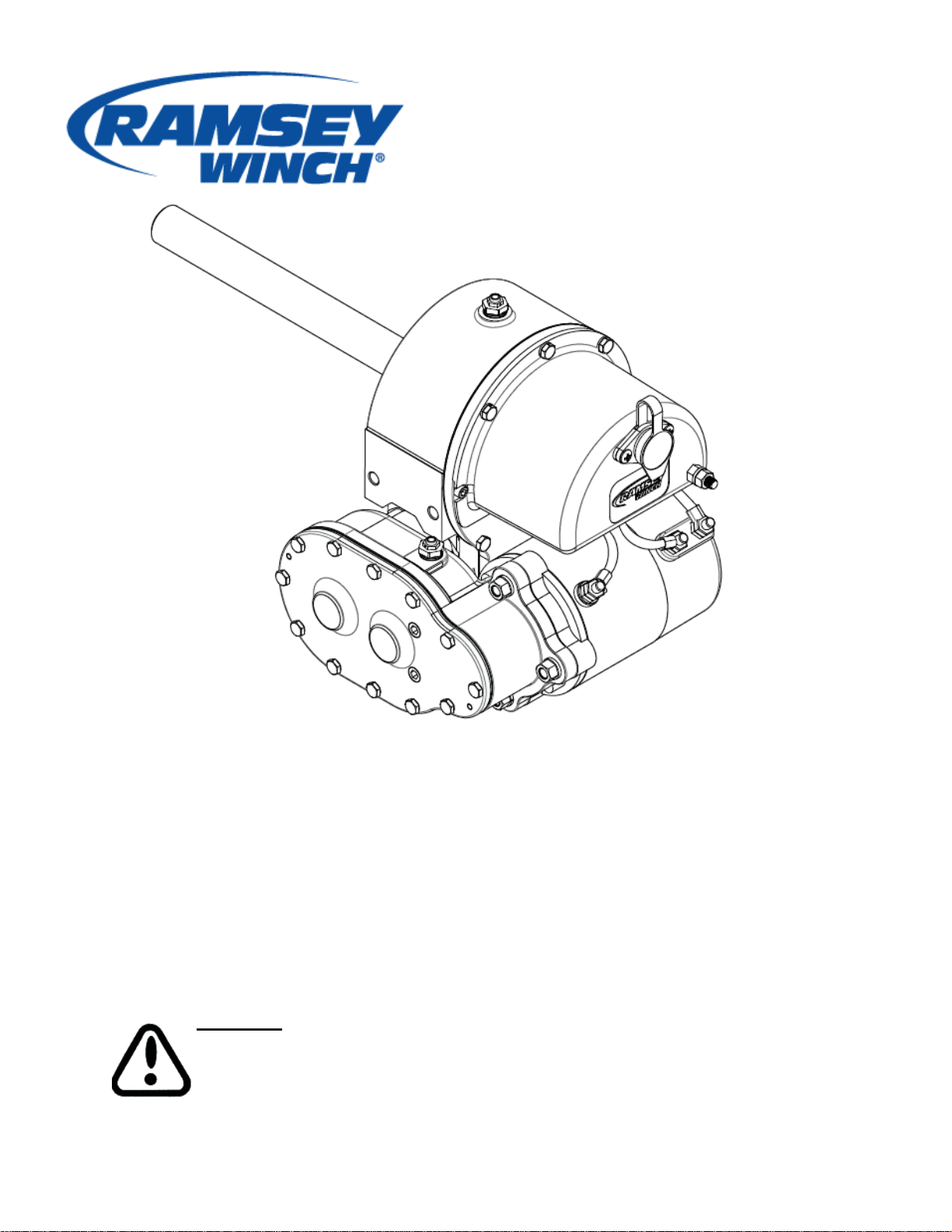
MODEL DCS-200
ELECTRIC INDUSTRIAL SPEED
REDUCER EZ ANCHOR
CAUTION: READ AND UNDERSTAND THIS MANUAL BEFORE
INSTALLATION AND OPERATION OF WINCH.
SEE WARNINGS!
Page 2

…
…
…
…
…
…
…
…
…
…
…
TABLE OF CONTENTS
INTRODUCTION ………………………………………
WARRANTY INFORMATION ………………………………………
SPECIFIC ATION ………………………………………
WARNINGS ………………………………………
MAINTENANCE ………………………………………
TR O U BLE SHOO TI NG GU IDE ………………………………………
INSTRUCTIONS FOR OVERHAUL OF RAMSEY MODEL DC-S200 SERIES
DISASSEMBLY & REASSEM BLY
………………………………………
DIM ENSIONAL DRAWIN G ………………………………………
PARTS LIST AND PART DR AWING ………………………………………
SOLENOID ………………………………………
LI M ITED WARRANTY ………………………………………
1
1
1
1
2
3-4
5-9
10
11-12
13
LA ST PAGE
2
Page 3
RAMSEY ELECTRIC SPEED REDUCER MODEL DCS-200 SERIES
PLEASE READ THIS MANUAL CAREFULLY
This manual contains useful ideas in obtaining the most effi cient operation from your
Ramsey Speed Reducer, and safety procedures one needs to know before operation.
WARRANTY INFORMATION
Ramsey Speed Reducers are designed and built to exacting specifi cations. Great
care and skill go into every speed reducer we make. If the need should arise, warranty procedure is outlined on the back of this manual. If you have any problems
with your speed reducer, please follow instructions for prompt service on all warranty
claims. Refer to back page for limited warranty.
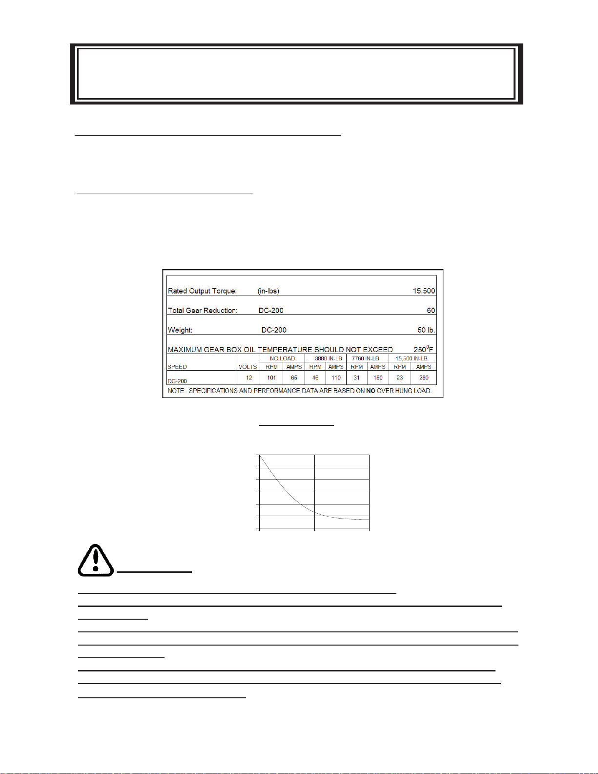
DUTY CYCLE
Speed reducer duty cycles is shown below:
6
5
4
3
MINUTES
2
1
0
180
270 360
AMPS
12V
WARNINGS
DO NOT EXCEED MAXIMUM RATINGS SHOWN IN THE TABLE.
DO NOT USE SPEED REDUCER TO LIFT, SUPPORT, OR OTHERWISE TRANSPORT
PERSONNEL.
DISCONNECT THE REMOTE CONTROL SWITCH FROM SPEED REDUCER WHEN NOT
IN USE. A RAMSEY PART NO. 282053 SAFETY ON-OFF SWITCH IN YOUR VEHICLE IS
RECOMMENDED.
IF A CABLE DRUM IS ADDED, A MINIMUM OF 5 WRAPS OF CABLE AROUND THE
DRUM IS NECESSARY TO SUPPORT THE RATED LOAD. A CABLE CLAMP IS NOT
DESIGNED TO HOLD THE LOAD.
Page 4

WINCH MAINTENANCE
Adhering to the following maintenance schedule will keep your speed reducer in top
condition and performing as it should with a minimum of repair.
A. WEEKLY
1. Check the oil level and maintain it to the oil level plug. If oil is leaking out,
determine location and repair.
2. Check the pressure relief plug in top of the gear housing. Be sure that it is
in good operating condition so that hot oil gasses may escape.
B. MONTHLY
1. Check the speed reducer bolts. If any are missing, replace them and secure ly tighten any that are loose. Make sure to use only grade 5 bolts or better.
C. ANNUALLY
1. Drain the oil from the speed reducer annually or more often if used
frequently.
2. Fill the speed reducer to the oil level plug with clean kerosene. Run the
speed reducer a few minutes with no load in the reel in direction. Drain the
kerosene from speed reducer.
3. Refi ll the speed reducer to the oil level plug with all purpose EP 140 gear
oil.
4. Inspect frame and surrounding structure for cracks or deformation.
5. Gear wear can be estimated by rocking the drum back and forth and if
necessary drain oil and remove cover for closer inspection.
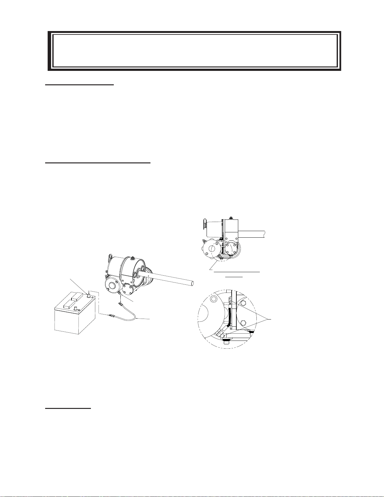
ELECTRICAL CONNECTIONS
See dimensional drawing on page 10. Using a power cable with appropriate end
terminals, connect the positive (+) battery terminal to the 5/16” dia. stud on the plastic
solenoid cover on the winch.
IMPORTANT: Hold inner nut on stud with a wrench while tightening outer nut. Using
a ground cable with appropriate end terminals, connect the negative (-) battery terminal to the 3/8” dia. bolt at motor. For distances up to 15 feet from battery to winch,
use #2 Ga. Wire for the above connections. For distances greater than 15 feet, use
wire larger than #2 Ga.
4
Page 5
WINCH MOUNTING
WINCH MOUNTING
It is most important that this winch be mounted securely so that the three major sections (the clutch housing end, the cable drum and the gear housing end) are properly
aligned.
All standard model DC-200 Series Winches are furnished with recommended mounting angles. Angle size is 1/4 x 2-1/2 x 2-1/2 x 36” Lg. high strength (50,000 PSI yield)
steel angle.
ELECTRICAL CONNECTIONS
See dimensional drawing on page 18. Using a power cable with appropriate end
terminals, connect the positive (+) battery terminal to the 5/16” dia. stud on the plastic
solenoid cover on the winch. In applications where the chassis is non-grounded, a
jumper wire (#440315) will be required between the winch and the motor ground. This
ground is required to insure a suffi cient ground to operate the solenoid assembly (see
diagram below).
WINCH WILL NOT OPERATE UNLESS
GROUND CABLE IS INSTALLED FROM THE
ISOLATED GROUND TERMINAL T O THE
NEGATIVE BATTERY POST.
(SEE DIAGRAM BELOW)
SEE ILLUSTRATION
NEGATIVE BATTERY POST
Isolated Motor Ground
ISOLATED GROUND
TERMINAL
GROUND CABLE
For non-grounded chassis applications
BELOW
JUMPER CABLE (#440315) MUST BE
INSTALLED ON WINCH FROM MOTOR
ISOLATED GROUND STUD TO GEAR
HOUSING COVER BOLT AS SHOWN
FOR NON GROUNDED CHASSIS
APPLICATIONS.
a jumper wire (#440315) is required to
ground the solenoid assembly.
IMPORTANT: hold inner nut on stud with a wrench while tightening outer nut. Using a
ground cable with appropriate end terminals, connect the negative(-) battery terminal
to the motor isolated ground terminal.
5
Page 6

TROUBLE SHOOTING GUIDE
CONDITION CORRECTIONPOSSIBLE CAUSE
OIL LEAKS FROM HOUSING
MOTOR RUNS IN ONE
DIRECTION
1. Seal damaged or worn.
2. Too much oil
3. Damaged gasket
1. Inoperative solenoid or
stuck solenoid.
2. Inoperative switch.
3. Broken wire or bad connection.
1. Replace seal.
2. Drain excess oil. Refer to
TECHNIQUES OF OPERATION.
3. Replace gasket.
1. Jar solenoid to free contacts.
Check by applying 12 volts to
coil terminal (it should make an
audible click when energized).
2. Disengage speed reducer
clutch or remove armature
lead. Remove switch plug
from hood. Raise connector cover on hood and with
a screw driver, short the
bottom two pins. Solenoid
should click. Short the two left
hand pins. The other solenoid should operate. If both
solenoids operate check for a
broken wire in switch cable.
3. Check for loose connection on
switch and switch connector.
MOTOR RUNS, BUT OUTPUT SHAFT DOES NOT
TURN.
1. Sheared drum shaft
key.
2. Stripped bronze
gear.
3. Parted shaft.
6
1-3. It will be necessary to
disassemble speed reducer
to determine cause and
repair.
Page 7

CONDITION CORRECTIONPOSSIBLE CAUSE
MOTOR RUNS EXTREMELY
HOT.
MOTOR RUNS, BUT WITH
INSUFFICIENT POWER, OR
WITH LOW RPM.
1. MOTOR WILL NOT OPER-
ATE.
1. Long period of operation.
2. Insuffi cient battery .
3. Electrical cables from
battery to speed reducer
too small.
4. Bad electrical connections.
5. Insuffi cient charging system.
1. Inoperative solenoid or
stuck solenoid
2. Inoperative switch.
3. Inoperative motor.
4. Loose connections.
1. Cooling-off periods are essen tial to prevent over-heating.
2. Check battery terminal volt
age under load. If 10 volts or
less, replace or parallel another
battery to it at motor terminal.
3. Must be #2 Ga. Wire for
distances up to 15 feet from
battery to speed reducer. Use
larger than #2 Ga. For
distances greater than 15 feet.
4. Check all connections for
looseness or corrosion;
Tighten, clean and grease.
5. Insuffi cient charging system.
1. Jar solenoid to free contacts.
Check by applying 12 volts to coil
terminal (it should make an
audible click when energized)
2. Disengage speed reducer clutch
or remove armature lead.
Remove switch plug from hood.
Raise connector cover on hood
and with a screw driver, short the
bottom two pins. Solenoid should
click. Short the two left hand pins.
Solenoid should click. Short the
two left pins. The other solenoid
should operate. If both solenoids
operate check for a broken wire in
switch cable.
3. If solenoids operate, check for
voltage at armature post; replace
motor.
4. Tighten connections on bottom
side of hood and on motor.
7
Page 8

INSTRUCTIONS FOR OVERHAUL OF RAMSEY
DCS-200 SPEED REDUCER
1. Drain oil from worm gear housing by
removing (item #35) plug from bottom
of gear housing. Remove relief fi tting
and reducer (items #32 & #34) from
top of gear housing. Remove Speed
Reducer from mounting.
2. Drain oil spur gear housing by removing
(item #35) plug. Remove cover and gasket
(items #5 & #29) from spur gear housing by
unscrewing twelve cap screws (item #20).
Slide gear (item #7) from end of worm shaft
(item#15) with gears attached. Check bearings (item#16) and thrust washers (item#44)
for signs of wear, replace if necessary.
Remove old bearings and press new bearings into place. Remove solenoid assembly
(item #1) by unscrewing cap screws (items
#22 and #24). Disconnect solenoid cables
from motor (item #33). Make note of which
terminals cables are attached to.
3. Remove key (item #11) and snap
ring (item #43) from worm shaft.
Remove motor (item #33) from
spur gear housing (item #9) by
removing (3) nuts and lock wash ers (items #25 and #27). Un-
screw (4) cap screws (item #23) to
remove spur gear box (item #9)
and gasket (item #28) from gear
housing. Replace lip seals (items
#40 & #42) by pressing old seals
from spur gear housing and press ing new seals into place.
8
Page 9

4. Remove bearing cap (item #3)
from gear housing by unscrewing
four cap screws (item #21).
Remove worm (item #15) and
bearing (item #17) from gear
housing. Use a soft hammer to
gently tap input end of worm
and drive worm and bearing from
gear housing. Once worm has
been removed from housing,
bearing can be pressed from end
of worm.
Check for signs of wear to worm
(item #15) and bearings (item
#17). Replace if necessary.
5. Remove gear housing cover (item #4)
from gear housing (item #10) by
unscrewing fi ve remaining cap screws
(item #21). Place cap screw into two
tapped holes of cover and tighten. This
will pull the cover loose from the gear
housing.
6. Check for signs of wear on gear
teeth. If replacement of gear is
necessary, gear must be replaced
as follows:
a. Press gear (item #8) from shaft
(item #14).
b. Examine shaft keys and key
ways. If distortion of keys and/
or keyways are evident, shaft
and keys should be replaced.
c. Use a soft hammer to gently
tap keys (item #31) into key
ways. Press gear (item #8) over
shaft and keys. Gear must be
centered over keys.
Remove cover gasket (item#30) and
pull shaft (item#14), with gear attached,
and thrust washer (item #46) from gear
housing.
9
Page 10

7. Remove seal (item #41) from back of
gear housing (item #10). Check bush ing (item #19) for signs of wear. Press
bushing (item #19) from gear housing
and replace if necessary. Press new
bushing and seal back into place.
8. Check cover bushing (item #18) for
signs of wear. Replace if necessary
by removing old bushing and pressing
new bushing into place.
13
12
7
9. Check gears of spur gear shaft assembly
for signs of wear, replace if necessary.
Press old gears from shaft (item #13). Tap
key (item #12) into keyway of shaft (item
#13). Press shaft through gears (item #7)
so that gears are centered on shaft and key.
7
10. Apply grease to end of shaft op posite gear. Apply grease to bush ing in gear housing (item #10).
Place greased end of shaft through
thrust washer (item #45) and bush ing in gear housing (item #10).
Place gasket (item #30) onto gear
housing cover (item #4). Apply
grease to gear end of shaft and
bushing in cover. Place thrust
washer (item #46) on gear end of
shaft. Place cover onto shaft and
secure to housing with fi ve (item
#21) cap screws at the fi ve lower
most holes.
10
Page 11

10. Press bearing (item #17) onto worm.
(item #15). NOTE: Be sure thick shoulder
of bearings outer race (side with
manufacturer’s name and part number) is
out, away from worm threads. Press
bearing and worm into gear housing. Slip
gasket (item #28) onto bearing cap (item
#3). Use four cap screws (item #21) to
secure cap to gear housing. Torque cap
screws to 7 ft-lbs (9.4 Nm) each.
Attach solenoid assembly (item #1) to
gear housing. Use two (item #24) cap
screws and three (item #22) cap screws
with three fl at washers (item #26).
Tighten cap screws to 7 ft-lbs. (9.4 Nm)
each. Insert plug (item #37) into tapped
hole of cover. Permatex may be applied
to threads to help prevent oil leakage.
TIGHTEN plug securely.
11. Press bearing (item #17) onto worm
and into worm gear housing. NOTE:
Be sure thick shoulder of bearings
outer race (side with manufacturer’s
name and number) is out, away
from worm threads. Place gasket (item
#28) onto spur gear housing (item #9).
Secure spur gear housing to worm gear
housing using four cap screws (item
#23). Torque cap screws to 7 ft-lbs (9.4
Nm) each.
Mount motor (item #33) to spur gear
housing (item #9) using three lock
washers and nuts (items #25 and #27).
Attach solenoid cables to motor
terminals. Tighten all nuts securely.
11
Page 12

12. Place snap ring (item #43) over
end of worm shaft (item #15) and set
into snap ring groove. Insert key
(item #11) into key way of worm
shaft. Place thrust washer (item
#44) over each end of spur gear
shaft (item #13). Set spur gear shaft
assembly into bearing of spur gear
housing. Slide gear (item #7) and
(item #44) thrust washer (item #44)
over end of worm shaft (item #15).
Insert pins (item #38) into cover (item
#5). Place gasket (item #29) onto
cover. Attach cover and gasket to spur
gear housing using twelve cap screws
(item #20).
Torque cap screws to 8 ft. lb. (10.8 Nm.) each. Insert plug (item #35) into bottom
of spur gear housing. Permatex may be applied to threads to help prevent oil
leakage. Remove reducer and fi tting (items #32 & #34) from top of spur gear
housing. Pour 1/2 pint of SAE 20 weight motor oil into spur gear box. Replace reducer and fi tting into top of spur gear housing. Tighten reducer and fi tting securely .
13. When mounting the speed reducer
torque to 34 ft. Lb. (46 Nm) each.
Insert plug (item #35) into bottom of
gear housing. Permatex may be
applied to threads to help prevent
leakage. Pour 3/4 pint of EP 140
gear oil into housing thru hole in top
of housing. Insert relief fi tting (item
#32) into reducer (item #34).
Reducer should then be placed into
hole on top of gear housing. Tighten
fi tting and reducer securely.
12
Page 13

NOTES
13
Page 14

273,6
10.77
7.44
188.9
3.72
94,4
DIMENSIONAL DRAWING
DCS-200
7.05
92,1
3.63
271,3
10.68
10.77
179,1
273,6
FROM NEGATIVE
BATTER Y TERMINAL TO
MOTOR GROUND STUD
CONNECT GROUND CABLE
6.85
173,9
CONNECT POWER CABLE
FROM POSITIVE
BATTER Y TERMINAL HERE
A
2.50
63,5
C
MM
INCHES
34,9
4.00
101,6
B
1.25
1.13
28,7
1.37
DIMENSIONS SHOWN ARE INCHES OVER MILLIMETERS
C
B
INCHES
A
INCHES
WINCH
MM
MM
MODEL
17.55
445,7
260,1
10.24
8.50
215,9
160417
20.05
12.74
11.00
160418
509,3
21.55
14.24
12.50
279,4 323,6
25.49
547,4
18.18
361,7
317,5
16.44
160419
647,4
417,6 461,8
160420
14
Page 15

MODEL DCS - 200 12V
EXPLODED VIEW
39
1
22
26
37
24
COMPONENT BREAKDOWN
SEE PAGE 18 FOR
21
3
28
17
15
11
43
10
32
34
31
14
41
31
17
28
4
30
45
19
40
34
32
9
18
46
8
35
23
33
42
27
25
35
44
13
12
16
6
21
2
47
7
7
44
16
15
44
16
29
38
5
38
36
20
Page 16

PARTS LIST
MODEL DCS-200
442185 GASKET
1PIN
M O DEL DC- S200 SPEED REDUCER ®
NO QTY. PART NO. DESCRIPTION
ITEM
1 357556 SHAFT 1 1/4 X 15.894 38 2 47000
1 357555 SHAFT 1 1/4 X 14.394 37 1 468018 PIP E P LUG SOC. HD
1 357557 SHAFT 1 1/4 X 19.832 39 1 482013 RUBBER BOOT
9 1 338203 HOUSI NG SPUR GEA R 31 4 450016 KEY (BA RTH)
1 1 278027 SOLENOID ASSEMBLY - 12V 23 4 414845 CAP SCREW 1/4 - 20NC X 1 LG. SOC. HD. NYLOK
2 1 282001 SWTICH ASSEMBLY 24 2 420012 CAPSCREW-1/4-20NCX3/4LG,HXSOCHD, SS
3 1 316083 CAP BEARING 25 3 418528 NUT-3/8- 24N F HEX REG, STAINLESS STEEL
4 1 328134 COVER WORM GEAR HSG 26 3 418529 WASHER- 1/4 FLAT STAIN LESS STEEL
NO QTY. PART NO. DESCRIPTION
ITEM
5 1 328106 COVER SP UR GEAR HSG 27 3 428530 LOCKWASHER-3/8 MED SECT, STA INLESS STEEL
8 1 334161 GEA R R. H. - 60:1 30 1 442205 GASKET
7 2 334003 GEA R 29 1
6 1 334239 GEA R 28 2 442184 GASKET
11 1 342023 KEY SQUARE 33 1 262037 MOTOR 12V
10 1 338273 HOUSING GEAR 32 2 456008 RELIEF FITTING
16
14 1 357554 SHAFT 1 1/4 X 11.894 36 2 468017 PIPE PLUG SOC. HD
13 1 356901 SHAFT SPUR 35 2 468011 PIPE PLUG SQ. HD
12 1 342033 KEY SQUARE 34 2 468002 REDUCER
16 3 402001 BEA RIN G N EEDLE 41 1 486017 OIL SEAL
17 2 402002 BEA RIN G BALL 42 1 486023 OIL SEAL
15 1 368001 WORM RH 60:1 40 1 486009 OIL SEAL
20 12 420009 CA PSCREW-1/4-20NCX3/4,HXHD, SS 45 1 518015 THRUST WASHER
19 1 412045 BUSHING 44 3 518002 THRUST WASHER
18 1 412044 BUSHING 43 1 490003 SN AP RING
21 9 420010 CAPSCREW-1/4-20NCX7/8 LG. HEX HD, SS 46 1 518040 THRUST WASHER
22 3 420011 CA PSCREW-1/4-20NCX1LG, HXHD, SS 47 4 418535 FLANGE NUT
Page 17

SOLENOID ASSEMBLY P ARTS
ITEM NO. QTY. PART NO DESCRIPTION
1 1 280009 CABLE - BOLT ASS 'Y
2 3 289077 WIRE ASS'Y
3 1 289091 WIRE ASS'Y
4 2 364001 STRAP
5 2 364002 STRAP
6 1 408035 SOLENOID BRA CKET
7 2 416283 SCREW-#10-24UN C SS
8 2 416277 SCREW-#10-24UN C
9 2 418536 NUT-HEX #10-24NC REG., SS
10 2 418531 NUT-5/16- 18NC HEX REG., SS
11 2 418140 WASHER-#10 FLAT ZI NC P LT
12 1 418532 LOCKWASHER-5/16 SS
13 1 418533 WASHER-5/16, S/P, SS
14 1 418534 WASHER-5/16 S/P, SS
15 1 430013 FEMA LE CONN E
CTOR
16 2 440071 TERMINAL TAB
17 2 440110 SOLEN OID-12V
18 1 472071 COVER
19 1 482029 COVER- CONNECTOR
8
8
20 4 530106 COVER- TERMINA L
278204—12V
16
20
12
9
19
7
11
To Yellow
17
18
7
11
4
2
To Red
10
13
10
To Green
14
15
17
6
5
3
1
21
9
4
18
5
3
3
21
17
21
21
Page 18

LIMITED WARRANTY
RAMSEY WINCH warrants each new RAMSEY Winch to be free from defects in material and
workmanship for a period of one (1) year from date of purchase.
e obligation under this warranty, statutory or otherwise, is limited to the replacement or repair
at the Manufacturer’s factory, or at a point designated by the Manufacturer, of such part that
shall appear to the Manufacturer, upon inspection of such part, to have been defective in material or workmanship.
is warranty does not obligate RAMSEY WINCH to bear the cost of labor or transportation
charges in connection with the replacement or repair of defective parts, nor shall it
apply to a product upon which repair or alterations have been made, unless authorized by Manufacturer, or for equipment misused, neglected or which has not been installed correctly.
RAMSEY WINCH shall in no event be liable for special or consequential damages. RAMSEY
WINCH makes no warranty in respect to accessories such as being subject to the warranties of
their respective manufacturers.
RAMSEY WINCH, whose policy is one of continuous improvement, reserves the right to improve its products through changes in design or materials as it may deem desirable without being
obligated to incorporate such changes in products of prior manufacture.
If eld service at the request of the Buyer is rendered and the fault is found not to be with
RAMSEY WINCH’s product, the Buyer shall pay the time and expense to the eld representative. Bills for service, labor or other expenses that have been incurred by the Buyer without approval or authorization by RAMSEY WINCH will not be accepted
RAMSEY WINCH COMPANY
Post Offi ce Box 581510 Tulsa, Oklahoma 74158-1510
Telephone: (918) 438-2760 FAX: (918) 438-6688
OM 912712-1013-B
 Loading...