

Page 1
OPERATING, SERVICE
AND MAINTENANCE
MANUAL
MODEL DC-200 SERIES
RAM-LOK®EQUIPPED
INDUSTRIAL LOW-MOUNT WINCHES
INCLUDES: DC-200/DC-246, DC-24-200/DC-24-246.
DCY-200/DCY-246, DCY-24-200/DCY-24-246
AND MODELS EQUIPPED WITH OPTIONAL ADJUSTABLE, AUTOMATIC OIL COOLED SAFETY BRAKE: DCG-200, DCYG-200 SE-
RIES WINCHES
CAUTION: READ AND UNDERSTAND THIS MANUAL BEFORE
INSTALLATION AND OPERATION OF WINCH. SEE SAFEGUARDS AND WARNINGS!
Page 2

TABLE OF CONTENTS
INTRODUCTIO
N................................................................................................1
WARRANTY INFOR MATION............................................................................
SPECIFICATION............................................................................................... 1
TECHNIQUES OF OPERATION....................................................................... 2
WARNINGS....................................................................................................... 2
WINCH MAINTENANCE................................................................................... 3
WINCH MOUNTING.......................................................................................... 4
ELECTRICAL CONNECTIONS......................................................................... 4
CABLE INSTALLATION.................................................................................... 4
ADJUSTING THE OIL COOLED SAFETY BRAKE........................................... 4
SERVICING OF THE OIL COOLED SAFETY
RE-ASSEMBLING
AND CHECKING THE
BRAKE......................................5
BRAKE........................................... 6
TEST FOR PROPER BRAKE ASSEMBLY....................................................... 6
INSTRUCTIONS FOR CHECKING ASSEMBLY
ARRANGEME N T AND SETTING OF WORM BRAKE................. .....................
TROUBLE SHOOTING GUIDE..................................................................... 8-9
INSTRUCTIONS FOR OVERHAUL OF
RAMSEY MODEL DC-200 SERIES RAM-LOK®
WINCHES
1
7
DISASSEMBL Y
REASSEMBL Y
............................................................................10-13
.............................................................................13-16
DIMENS IONA L DR AW ING............................................................................. 17
PARTS LIST AND PARTS DRAW ING
SOLENOID AND SWITCH ASSEMBLY PARTS
TEST PROCEDURE FOR
TEST PROCEDURE FOR
MOTOR ASSEMBLY PARTS
SOLENOID.......................................................... 22
MOTOR............................................................... 23
LIST................................................................ 24
........................................................18-20
LIST.................................... 21
LIMITED WARRANTY.................................................................................... 25
Page 3

(
(
(
RAMSEY ELECTRICAL WINCH MODEL DC-200 SERIES
PLEASE READ THIS MANUAL CAREFULLY.
This manual contains useful ideas in obtaining the most effi cient operation from your Ramsey Winch,
and safety procedures one needs to know before operating a Ramsey Winch.
WARRANTY INFORMATION
Ramsey Winches are designed and built to exacting specifi cations. Great care and skill go into every
winch we make. If the need should arise, warranty procedure is outlined on the back of your self-addressed postage paid warranty card. Please read and fi ll out the enclosed warranty card and send it
to Ramsey Winch Company. If you have any problems with your winch, please follow instructions for
prompt service on all warranty claims. Refer to back page for limited warranty.
*SPECIFICATIONS: Conforms to SAE J706
Rated Line Pull 1st Layer (l bs.)................................................................................................ 8,000
(kgs.)................................................................................................ 3,630
Total Gear Reduction: D C -200..............................................................................
DC-246.................................................................................................... 360
Weight: DC-200/DC-246 (long drum) ..................................................................
DCY-200/DCY-246 (short drum)..............................................................
MAXIMUM GEAR BOX OIL TEMPERATURE SHOULD NOT EXCEED................................................ 2500F
Layer of Cable 1 2 3 4
Rated Line Pull Lbs. 8,000 6,700 5,700 5,000
per layer
Long Drum Cable
capacity per layer
"Y"
Short
Drum
cable c apaci ty
per layer
Kgs. 3,620 3,030 2,580 2,260
Ft. 25 60 95 140
M. 7 18 28 42
Ft.
M.
15 30 55
4
9
NO LOAD 2000#LOAD 4000# LOAD 8000# LOAD
Line Speed
VOLTS (MPM)
FPM FPM FPM FPM
AMPS
(MPM)
AMPS
(MPM)
DC-200/DCY-200 12 14 65 7 110 5 180 3.5
DC-24-200/DCY-24-200
(4.3). 30 (2.1). 50
24
DC-246/DCY-246 12 16.5 70 8.5 140 5.5
DC-24-246/DCY-24/246
(5)· 35 (2.5). 70
24
*These specifi cations are based on recommended 3/8 inch dia. extra improved
plow steel wire rope or equivalent.
Winch only conforms to SAE J706. For SAE qualifi cation of mounting angles,
if applicable, consult Ramsey Engineering.
....................... 470
16
(MPM)
AMPS
1.5). 90
1.7).
(1.1).
200
100
116 lb. ( 52. 6
105 lb. ( 47. 6
75
22
AMPS
280
140
3.5 330
1.1). 160
Kgs.)
Kgs.)
NOTE: The rated line pulls shown are for the winch only. Consult the wire rope manufacturer for wire rope ratings.
Winch duty cycles are shown below:
6
5
4
3
MINUTES
2
1
0
180
270 360
AMPS
5
4
3
2
MINUTES
1
0
90 120 160 190
AMPS
12V 24 V
1
Page 4
TECHNIQUES OF OPERATION
The best way to get acquainted with how your winch operates is to make test runs before you actually
use it. Plan your test in advance. Remember, you hear your winch, as well as see it operate. Get to
recognize the sounds of a light steady pull, a heavy pull, and sounds caused by load jerking or shifting.
Gain confi dence in operating your winch and its use will become second nature with you.
The uneven spooling of cable, while pulling a load, is not a problem, unless there is a cable pileup on
one end of drum. If this happens, reverse the winch to relieve the load and move your anchor point
further to the center of the vehicle. After the job is done you can unspool and rewind for a neat lay of
the cable.
When pulling a load where there is even a remote chance of cable failure, place a blanket, jacket or
tarpaulin over the cable about six feet behind the hook. This will slow the snap back of a broken cable
and could prevent serious injury.
Check oil level of winch every six months. Replace oil annually or more often if winch is used frequently. Use 3/4 pint of all purpose E. P. 140 oil in the worm gear housing and 1/2 pint SAE 20 for spur gear
box. If the oil is contaminated with metallic particles, inspect winch for cause of abnormal wear. Periodically check all electrical connections and mounting bolts. Tighten hardware if necessary.
The minimum ampere-hour rating of vehicle battery should be 70, and used with at least a 40 amp
alternator. An Auxiliary battery is recommended to supply additional battery power. Inspect the cable
frequently. If the cable becomes frayed with broken strands, replace immediately. Cable and hook assembly may be purchased from a Ramsey distributor. The RAM-LOK® semi-automatic clutch allows
rapid unspooling of the cable, from cable drum, for hooking onto a load. The clutch is operated by the
“T-handle”, located on the end of the winch, as follows:
1. TO DISENGAGE CLUTCH, run the winch in the reverse (reel out) direction until the load is off the
0
cable. Pull outward on the clutch handle, rotate it counter-clockwise 90
now locked out and the cable may be pulled off by hand.
2. TO ENGAGE CLUTCH, pull outward on the handle, rotate it clockwise 900 and release. Run the
winch in reverse until the clutch handle snaps fully in or until the cable drum starts turning. At this
point make sure the clutch handle is all the way in. The plastic plug in top of clutch housing may be
removed, for inspection of clutch to assure total engagement. After the clutch is fully engaged, the
winch is ready for winching in the cable.
WARNINGS
and release. The clutch is
CLUTCH MUST BE TOTALLY ENGAGED BEFORE STARTING THE WINCHING OPERATION.
DO NOT DISENGAGE CLUTCH UNDER LOAD.
DO NOT LEAVE CLUTCH ENGAGED WHEN WINCH IS NOT IN USE.
STAY OUT FROM UNDER AND AWAY FROM RAISED LOADS.
STAND CLEAR OF CABLE WHILE PULLING. DO NOT TRY TO GUIDE CABLE.
DO NOT EXCEED MAXIMUM LINE PULL RATINGS SHOWN IN TABLE.
DO NOT USE WINCH TO LIFT, SUPPORT, OR OTHERWISE TRANSPORT PERSONNEL.
A MINIMUM OF 5 WRAPS OF CABLE AROUND THE DRUM BARREL IS NECESSARY TO HOLD
THE LOAD. CABLE CLAMP IS NOT DESIGNED TO HOLD LOAD.
DISCONNECT THE REMOTE CONTROL SWITCH FROM WINCH WHEN NOT IN USE. A RAMSEY
PART NO. 282053 SAFETY ON-OFF SWITCH IN YOUR VEHICLE IS RECOMMENDED.
2
Page 5

WINCH MAINTENANCE
Adhering to the following maintenance schedule will keep your winch in top condition and
performing as it should with a minimum of repair.
A. WEEKLY
1. Check the oil level and maintain it to the oil level plug. If oil is leaking out, determine loca tion and repair.
2. Check the pressure relief plug in top of the gear housing. Be sure that it is in good operat ing condition so that hot oil gasses may escape.
3. Lubricate cable with light oil.
B. MONTHLY
1. Lubricate the various grease fi ttings located in the cable drum, end bearing, clutch hous-
ing or clutch operating linkage. Any good grade of moly-disulfi de containing grease is
acceptable.
2. Check the action of the sliding clutch, making sure it is fully engaging and disengaging
with the cable drum. Remove the plastic plug in top of the housing and observe if the
clutch is fully engaging. If clutch is not fully engaging, inspect clutch shifter assembly
parts, check for damage or excessive wear and replace as necessary. Observe the jaws
on both the clutch and cable drum, checking for rounding of the driving faces. If rounding
has occurred they should be replaced immediately.
3. Check the winch mounting bolts. If any are missing, replace them and securely tighten
any that are loose. Make sure to use only grade 5 bolts or better.
4. Check the torque setting of the oil cooled worm brake. Make any adjustments re quired, following the procedure described in ADJUSTING THE OIL COOLED WORM
BRAKE in the Owner’s Manual.
5. Check alignment of chain and sprockets and adjust as required to minimize wear.
6. Inspect the cable. If the cable has become frayed with broken strands, replace
immediately.
C. ANNUALLY
1. Drain the oil from the winch annually or more often if winch is used frequently.
2. Fill the winch to the oil level plug with clean kerosene. Run the winch a few minutes with
no load in the reel in direction. Drain the kerosene from the winch.
3. Refi ll the winch to the oil level plug with all purpose EP 140 gear oil.
4. Inspect frame and surrounding structure for cracks or deformation.
5. Gear wear can be estimated by rocking the drum back and forth and if necessary drain oil
and remove cover for closer inspection.
3
Page 6
WINCH MOUNTING
WINCH MOUNTING
It is most important that this Winch be mounted securely so that the three major sections (the
clutch housing end, the cable drum and the gear housing end) are properly aligned. All standard
model DC-200 Series winches are furnished with recommended mounting angles. Angle size is 1/4
x 2-1/2 x 2-1/2 x 36” Lg. high strength (50,000 PSI yield) steel angle.
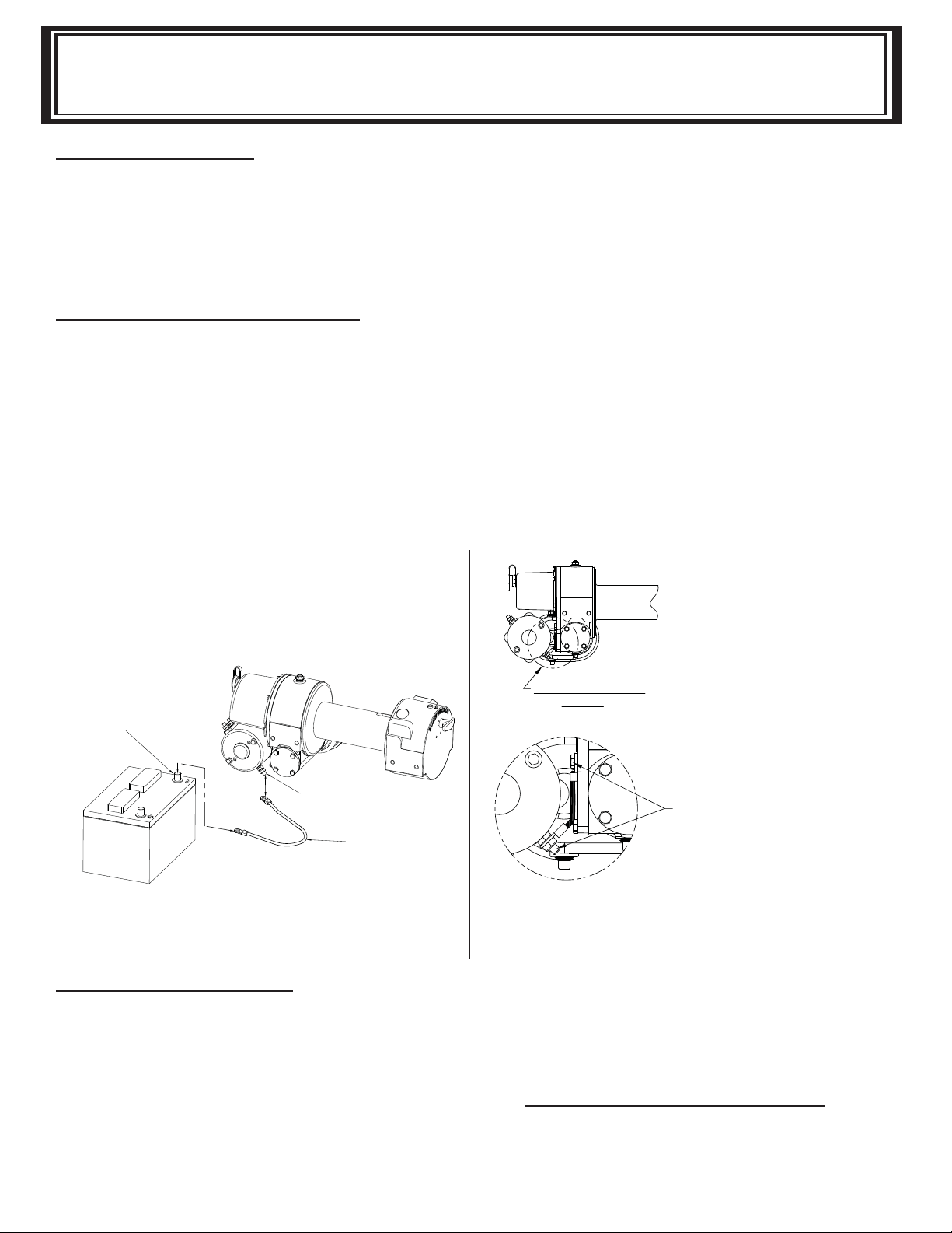
ELECTRICAL CONNECTIONS
See dimensional drawing on page 17. Using a power cable with appropriate end terminals, connect
the positive (+) battery terminal to the 5/16” dia. stud on the plastic solenoid cover on the winch.
IMPORTANT: hold inner nut on stud with a wrench while tightening outer nut. Using a ground cable
with appropriate end terminals, connect the negative(-) battery terminal to the motor isolated ground
terminal. In applications where the chassis is non-grounded, a jumper wire (#440315) will be required
between the winch and the motor isolated ground terminal. This ground is required to insure a suffi -
cient ground to operate the solenoid assembly (see diagram below). For distances up to 15 feet from
battery to winch, use #2 Ga. wire for the above connections. For distances greater than 15 feet, use
wire larger than #2 Ga.
WINCH WILL NOT OPERATE UNLESS
GROUND CABLE IS INSTALLED FROM THE
ISOLATED GROUND TERMINAL TO THE
NEGATIVE BATTERY POST.
(SEE DIAGRAM BELOW)
NEGATIVE BATTERY POST
Isolated Motor Ground
CABLE INSTALLATION
ISOLATED GROUND
TERMINAL
GROUND CABLE
SEE ILLUSTRATION
BELOW
JUMPER CABLE (#440315) MUST BE
INSTALLED ON WINCH FROM MOTOR
ISOLATED GROUND STUD TO GEAR
HOUSING COVER BOLT AS SHOWN
FOR NON GROUNDED CHASSIS
APPLICATIONS.
For non-grounded chassis applications
a jumper wire (#440315) is required to
ground the solenoid assembly.
1. Unwind cable by rolling it out along the ground to prevent kinking. Securely wrap end of cable,
oppo site hook, with plastic or similar tape to prevent fraying.
2. Insert the end of cable, opposite hook end, into the 7/16” dia. hole in drum barrel. Secure cable
to drum barrel, using setscrew furnished with winch. TIGHTEN SETSCREW SECURELY.
3. Carefully run winch in the “reel-in” direction. Keeping tension on end of cable, spool all the cable
onto the cable drum,taking care to form neatly wrapped layers.
4
Page 7
WORM BRAKE ADJUSTMENT
ADJUSTING THE OIL COOLED WORM BRAKE
The oil-cooled, fully adjustable, automatic safety brake operates in the worm housing lubricant,
all parts being submerged in oil. When the brake wears to the point that the load begins to drift,
the brake can be adjusted as follows:
1. Loosen the lock nut on the adjusting screw.
2. Tighten the brake by turning the adjusting screw clockwise.
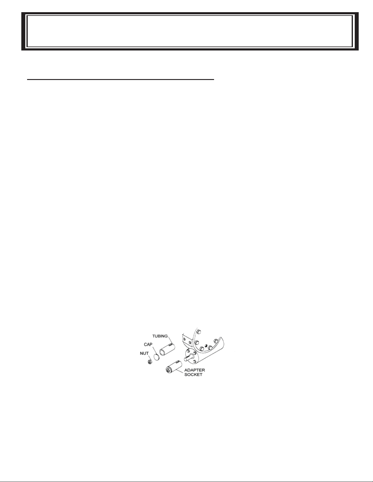
CAUTION: Only 1/4 turn is usually required to adjust the brake. Over-tightening can cause over
heating, and damage to the brake parts. Tighten the lock nut after adjustment is completed. If the
brake does not respond to adjustment then a new leaf spring and brake disc is needed. A torque
wrench can be equipped with a special adapter to fi t the input shaft (worm) of the winch. The
adapter can be made by welding a nut to the end of a piece of tubing as shown in the following
fi gure.
After welding the cap and nut to the tubing, slot the tubing as shown. This will allow the special
adapter to slide over the keyway and will then act as a large socket. A torque wrench can then
be used to apply the proper torque. Turn the torque wrench so that the drum turns in the spool
out direction or lowering direction. The torque rating for the Model 200/246 should be 8 to 13ft.
lbs. (D-200, 13 to 18ft. lbs.).
If the torque wrench does not show the proper value as it turns the worm brake adjusting bolt
should be turned clockwise 1/4 turn. Each time the adjusting bolt is turned, check the torque reading. Continue this procedure until the proper torque reading is achieved. Then tighten the lock
nut.
If the torque wrench does not show the proper value as it turns the worm brake adjusting bolt
should be turned clockwise 1/4 turn. Each time the adjusting bolt is turned, check the torque reading. Continue this procedure until the proper torque reading is achieved. Then tighten the lock
nut.
5
Page 8
SERVICING OF THE OIL COOLED SAFETY BRAKE
SERVICING OF THE OIL COOLED SAFETY BRAKE
1. Remove the drain plug and drain the worm gear oil from the worm housing.
2. Back off the lock nut, then the adjusting screw, both two turns or more by turning them
counter-clockwise.
3. Remove the cover mounting screws.
4. Remove the cover along with coil spring and leaf spring.
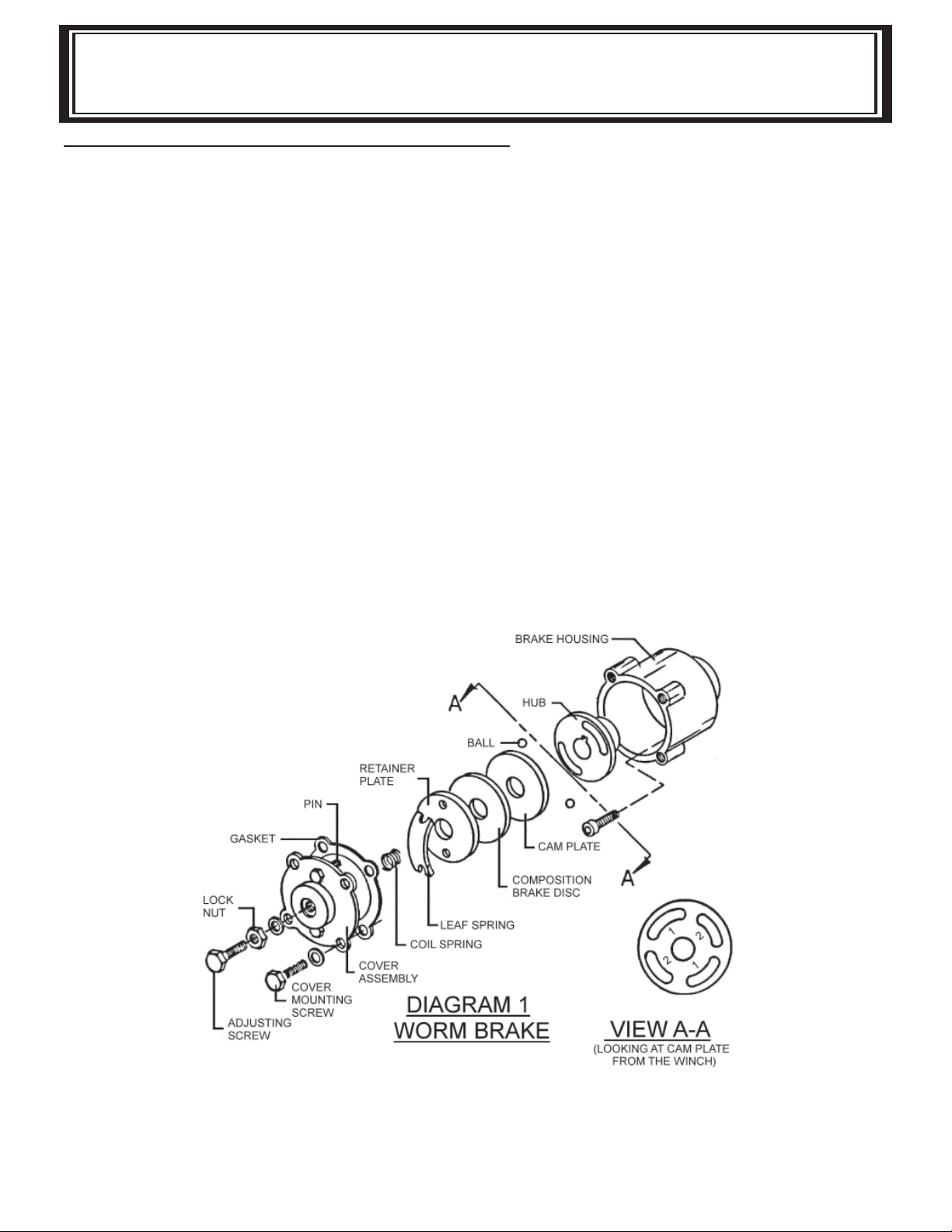
5. Remove the retainer plate, composition brake disc, cam plate and balls. Note, the slots the balls
are in.
6. Inspect parts as follows:
a). Composition brake discs are 1/8” thick when new. Replace if thinner than 0.080” or if
surfaces are glazed or burnt.
b). Inspect the fl at, ground surface of the cam plate and retainer plate for glazing, warpage,
or other damage. Glazing can be removed by scraping carefully.
c). Inspect the leaf spring. It should be bowed 1/8”.
6
Page 9

BRAKE - CHECKING / RE-ASSEMBLY AND TESTING
BRAKE RE-ASSEMBLY
1. Press brake hub into place over worm shaft and key.
2. Assemble ball into appropriate slots of cam. (Refer to diagram 1, page 5). Use stiff grease
to hold balls into place and slide cam over end of worm. Be sure that balls are secure,
between cam slots and hub slots. Refer to Page 7 to determine proper ball slot setting.
3. Install brake disc.
4. Install retainer plate, smooth side toward brake disc.
5. Install the gasket on the cover with a small amount of grease or sealer.
6. The coil spring goes over the adjusting screw on the inside of the cover.
7. Install the notches of the leaf spring on the pins protruding through the cover.
The hollow side of the leaf spring goes toward the brake.
8. Install brake housing cover, making sure the protruding pins go through the leaf spring and
into the holes in the retainer plate.
9. Bolt cover into place with the mounting screws. Install drain plug and add 1 pint all
purpose EP 140 oil.
10. Turn winch in the hoisting direction at least one turn of the input shaft.
11. Turn the adjusting screw in until it is fi nger tight.
TEST FOR PROPER BRAKE ASSEMBLY
After the brake has been adjusted to the proper torque setting disengage clutch. Start vehicle
engine and run winch in the reel in (hoisting direction). Allow winch to run in this direction for one
minute.
Place your hand on the safety brake housing. If housing is not hot to the touch then run winch in
the reverse direction (cable out) for one minute. Brake housing should begin to heat.
When these conditions exist, proper installation has been made. If heating becomes noticeable
when running the winch in forward rotation (hoisting direction), the brake should be again disassembled. When disassembled, place the brake balls in the alternate set of slots in the cam plate,
then carefully follow the instructions for re-assembling and checking the brake.
7
Page 10

INSTRUCTIONS FOR CHECKING ASSEMBLY ARRANGEMENT
AND
SETTING OF WORM BRAKE
When the worm brake is assembled the brake must be set with the balls in the #1 or the #2 set of
cam slots. (View A-A, page 5). It is indicated on the name plate whether the balls were installed in
the #1 or the #2 slots at the factory.
Three factors determine which slots the balls should be in:
1. Direction cable winds on the drum. It normally WINDS OVER THE TOP of the drum barrel.
2. The side of the winch that the input shaft is on. The INPUT SHAFT IS NORMALLY TOWARD
THE CAB. Whether the winch has the gear box on the right or on the left side of the winch does
not affect the brake setting.
EXAMPLE: When cable winds over the top of the drum, winch has a right cut gear and input shaft
is toward the cab (diagram 2) , then the balls need to be in the #2 cam slots.
If any one of these three factors differ from those stated above, the balls need to be in the #1 slots in
the cam. A second change in these factors requires the original arrangement,and if all three factors
are different, the balls need to be in the #1 slots. (See page 5 and 6 for disassembly and assembly
instructions).
DIAGRAM 2
Input side of winch
toward cab
Cable winds
over top
8
Page 11

TROUBLE SHOOTING GUIDE
TROUBLE SHOOTING GUIDE
CONDITION
CLUTCH INOPERATIVE OR BINDS
UP.
OIL LEAKS FROM HOUSING.
LOAD DRIFTS DOWN.
CABLE DRUM WILL NOT FREE
SPOOL.
CABLE BIRDNESTS WHEN CLUTCH
IS
MOTOR RUNS IN ONE DIRECTION
ONLY.
MOTOR RUNS, BUT DRUM DOES
NOT TURN.
DISENr,Ar,F:rr
POSSIBLE CAUSE
1. Dry or rusted shaft.
2. Bent yoke or linkage.
3. Clutch j aws are
contact.
1. Seal damaged or worn.
2. Too much oil.
3. Damaged gas ket.
1. Safety brake has
becomewom.
2. Safety brake out of
adjustment.
1. Winc h no t m o u nt e d
squarely, causing
bearings to bind drum .
1. Drag brake disc worn.
1. Inoperative solenoid
or stuck soleno id.
2. Inoperative switch.
3. Broken wire or
connection.
1. Clutch not engaged.
2. Sheared drum shaft key.
3. Stripped bronze gear.
4. Parted shaf t .
9
in
end
CORRECTION
1. Clean and lubricate.
2. Replace yoke or shaf t
assembly.
3. See TECHNIQUES OF
OPERATION.
1. Replace seal.
2. Drain excess oil. Refer to
TECHNIQUES OF OPERATION.
3. Replace gasket.
1. Replace brake disc. (S ee
Page 5, Diagram
2. Tum adj usting bolt
wise 1/4 tum or until
load does not drift.
1. Check m ounting. Ref er to
WINCH MOUNTING Page 4.
.
1
)
clock-
bad
1. Replace discs.
1. Jar so leno id t o free
contacts. Check by applying
12 volts to coil terminal
should make an audible
click when energized).
2. D ise ng ag e w inc h c l utc h
remove armature lead.
Remove switch plug from
hood. Raise connector cover
on hood and with a screw
driver, short the bottom
two pins. Solenoid should
click. S hort the two left
hand p ins. The ot her
solenoid should operate.
If bo th sole no ids
check for a broken wire in
switc h cabl e.
3. Check for loose connection
on switc h a nd swi tc h
connector.
1-4. If clutch engaged b ut
symptom still exists, it
will be necessary to
assemble winch to
determine cause and repair.
operate
dis-
it
(
or
Page 12

CONDITION
POSSIBLE CAUSE
CORRECTION
MOTOR RUNS EX TREMELY HOT.
MOTOR RUNS, BU T WITH
INSUFFICIENT POWER, OR WITH
LOW LINE SPEED.
MOTOR WILL NOT OPERATE.
1. Long period of operation.
2. Insufficient b att er y.
3. Electrical cables from
battery to winch too sma ll
4. Bad electr ica l
connections.
5. Insufficient charging
system.
1. Inoperative solenoid
or stuck solenoid.
2. Inoperative sw itc h.
3. Inoperative motor.
4. Loose co nnec t ions.
1. Cooling-off penods are
esse ntia l to pre vent ov erheating.
2. Check battery terminal
voltage under load. If 10
s or les s, rep lace
volt
parallel another battery
to it at motor terminal.
3. Must be #2 Ga. wire for
distances up to 15 feet from
battery to winch. Use larger
than #2 Ga. for distances
greater than 15 f eet.
or
4. Check all connections for
looseness or corrosion;
Tighten, clean and grease.
5. Replace with
capacity charging syst em.
1. Ja r so lenoid to fre e
contacts. Check by applying
12 volts to coil terminal
(it should make an audible
click when energized).
2. Disengage winch clutch or
remove armature lead. Remove switch plug from hood.
Raise connector cover on
hood a
driver, short the bottom
two pins. Solenoid s hould
click. S hort t he two left
pins. The other sole noid
should operate. If both
solenoids operate, check
for a broken wire in
switch cable.
3. If solenoids operate,
check for voltage at
armature post; replace motor.
4. Tighten connections on
bottom side of hood and on
motor.
larger
nd w it h a sc re w
10
Page 13

NOTES
11
Page 14

INSTRUCTIONS FOR OVERHAUL OF RAMSEY
MODEL DC-200 SERIES RAM-LOK
DIS-ASSEMBLY
1. Drain oil from gear housing by remov ing (item #54) plug from bottom of gear
housing. Remove relief fi ttings and re-
ducer (items #50 & #53) from top of gear
housing.
Remove mounting angles (items #4 &
#5) from winch by removing hardware
shown.
2. Drain oil from spur gear box by removing (item
#54) plug. Remove cover and gasket (items #9 &
#44) from spur gear housing by unscrewing
twelve capscrews (item #28). Slide gear (item
#12) from end of worm shaft (item #23). Remove
spur gear shaft (item #21), with gears attached.
Check bearings (item #24) and thrust washers
(item #68) for signs of wear, replace if necessary.
Remove old bearings and press new bearings
into place. Remove solenoid assembly (item # 2)
by unscrewing capscrews (items #30 & #34).
Disconnect solenoid cables from motor (item
#51). Make note of which terminals cable are
attached to.
3. Remove key (item #19) and snap ring (item
#65) from worm shaft. Remove motor (item
#51) from spur gear housing (item #16) by
removing (3) nuts and lockwashers (items
#39 & #41). Unscrew (4) capscrews (item
#33) to remove spur gear box (item#16)
and gasket (item #43) from gear housing.
Replace lip seals (items #62 & #64) by
pressing old seals from spur gear housing
and pressing new seals into place.
12
Page 15

4. Slide clutch housing (item #17) from end of drum
shaft. Slide jaw clutch (item #7) from end of drum
shaft.
Remove (2) keys (item # 47) from keyways . A
screw driver can be used, at notch, to aid in remov al of keys. Once keys have been removed, drum
(item#10) and thrust washer (item #70) can be
removed from drum shaft. Parts under drum, thrust
washer (item #69), spring and disc (items #66 &
#42) should also be removed.
5. Remove bearing cap (item #6) from gear
housing by unscrewing four capscrews (item
# 29 ). Remove worm (item #23 ) and bearing
(item #25) from gear housing. Use a soft ham mer to gently tap input end of worm and drive
worm and bearing from gear housing. Once
worm has been removed from housing, bear ing can be pressed from end of worm.
6. Remove gear housing cover (item #8) from
gear housing (item #18) by unscrewing fi ve
remaining capscrews (items #29). Place
capscrew into two tapped holes of cover and
tighten. This will pull the cover loose from gear
housing.
Remove cover gasket (item #45) and pull shaft
(item #22), with gear attached, and spacer
(item #70) from gear housing.
Check for signs of wear to worm (item #23)
and bearings (item #25). Replace if neces sary.
For models with optional worm brake refer to
page 5, SERVICING OF THE OIL COOLED
SAFETY BRAKE, for disassembly and page 6,
for re-assembly instructions.
13
Page 16

7. Check for signs of wear on gear teeth. If
replacement of gear is necessary, replace
as follows:
a) Press gear (item #14) from shaft (item
#22).
b) Examine shaft keys and keyways, if
distortion of keys and/or keyways is
evident, shaft and keys should be
replaced.
c) Use a soft hammer to gently tap keys
(item #48) into keyways. Press gear
(item #14) over shaft and keys. Gear
must be centered over keys.
8. Remove seal (item #63) from back of gear
housing (item #18). Check bushing (item
#27) for signs of wear. Press bushing
(item #27) from gear housing and replace
if necessary. Press new bushing and seal
back into place.
9. Check drum bushings (item #26) for
signs of wear. Replace if necessary by
pressing old bushings from drum
(item#10) and pressing new ones
into place.
10. Examine shifter assembly (item #1) for damage
to yoke. Yoke should be fi rmly attached to
shaft, yet, able to swivel freely around shaft.
Replace if necessary by removing pin (item
#58) from handle (item #15). Remove rubber
plug (item #59) from housing. Unscrew set screw enough to allow shifter assembly to be
removed from housing.
Check clutch housing bushing (item #26) for
signs of wear. Remove if necessary by press ing old bushing from housing (item #17) and
pressing new one into place.
Install new shifter assembly (item #1) by plac ing end of shaft, opposite yoke, through spring
(item #67) and into housing item(#17). Attach
(item #15) handle to shaft using roll pin (item
#58). Tighten setscrew, in housing, enough to
allow shifter assembly to operate properly.
Replace rubber plug.
14
Page 17

11. Check cover bushing (item #8) for signs of wear. Re place if necessary by removing old bushing and press ing new bushing into place.
12. Check pinion gear on motor for signs of wear. If
necessary replace motor (item # 51).
13. Check gears of spur gear shaft assembly for
signs of wear, replace if necessary. Press old
gears from shaft (item #21). Tap key (item #20)
into keyway of shaft (item #21). Press shaft
through gears so that gears are centered on
shaft and key.
RE-ASSEMBLY
14. Apply grease to end of shaft, opposite gear. Apply
grease to bushing in gear housing (Item#18). Place
greased end of shaft through spacer (item #71) and
bushing in gear housing (item #18). Place gasket (item
#51) onto gear housing cover (item #8). Apply grease to
gear end of shaft and bushing in cover.
Place cover onto shaft and secure to housing with fi ve
(item #29) capscrews at fi ve lower holes.
15
Page 18

15. Place winch, with gear housing cover down, on work
bench. Drum shaft should be in vertical position. Slide
thrust washer (item #69) over drum shaft and slide
downwards until washer rests on gear housing. Set
springs (item #66) and drag brake disc (item #42) into
pockets of gear housing. Grease bushings in drum
(item #10). Slide drum assembly onto drum shaft with
drum jaws upward.
16. Slide thrust washer (item #70) over end of drum
shaft. Press drum (item #10) downward to compress
drag brake springs in gear housing.
Insert keys (item #47) into keyways with sharp edge of
keys pointing outward and notched end of keys up ward. A rubber or brass mallet will be needed to gently
tap keys into position.
Apply grease to keys and end of shaft. Place jaw
clutch (item #7) over end of shaft and slide jaw clutch
over keys. Set clutch housing (item #17) over end of
drum shaft. Pull jaw clutch (item#7) upward, toward
clutch housing, enough to allow yoke, in clutch hous ing, to fi t properly in groove around jaw clutch.
16
Page 19

17. Press bearing (item #25) onto worm (item #23)
NOTE: Be sure thick shoulder of bearings outer
race (side with manufacturer's name and
number ) is out, away from worm threads. Press
bearing and worm into gear housing. Slip gasket
(item #43) onto bearing cap (item #6). Use four
capscrews (item #26) to secure cap to gear
hous ing. Torque capscrews to 7 ft-lbs. (9.4 Nm)
each.
Attach solenoid assembly (item #2) to gear hous ing. Use two (item #34) capscrews and three
(item #30) capscrews with three fl atwashers
(item #40). Tighten capscrews to 7 ft-lbs. (9.4
Nm) each. Insert plug (item #56) into tapped hole
of cover. Permatex may be applied to threads to
help prevent oil leakage. TIGHTEN plug
securely.
18. Press bearing (item #25) onto worm and
into worm gear housing. NOTE: Be sure
thick shoulder of bearings outer race
Iside with manufacturer's name and num ber) is out, away from worm threads.
Place gasket (item #43) onto spur gear
housing (item #16). Secure spur gear
housing to worm gear housing using four
capscrews (item #33). Torque capscrews
to 7 ft-lbs. (9.4 Nm) each.
Mount motor (item #51) to spur gear
housing (item #16) using three lockwash ers and nuts (items #39 & #41). Attach
solenoid cables to motor terminals.
Tighten all nuts securely.
17
Page 20

19. Place snap ring (item #65) over end of worm
shaft (item #23) and set into snap ring groove.
Insert key (item #19) into keyway of worm shaft.
Place thrust washer (item #68) over each end of
spur gear shaft (item #21). Set spur gear shaft
assembly into bearing of spur gear housing.
Slide gear (item #12) and(item #68) thrust
washer over end of worm shaft (item #23).
Insert pins (item #57) into cover (item #9 ).
Place gasket (item #44) onto cover. Attach cover
and gasket to spur gear housing using twelve
capscrews (item #28). Torque capscrews to 8 ft.
lb. (10.8 Nm.) each. Insert plug (item #54) into
bottom of spur gear housing. Permatex may be
applied to threads to help prevent oil leakage.
Remove reducer and fi tting (items #50 & #53)
from top of spur gear housing. Pour 1/ 2 pint of
SAE 20 weight motor oil into spur gear box.
Replace reducer and fi tting into top of spur gear
housing. Tighten reducer and fi tting securely .
20. Attach mounting angles (items #4 & #5)
using six capscrews (item #32) with lock
washers and capscrews (items #35 &
#31) . Torque capscrews to 34 ft. lb. (46
Nm.) each. Insert plug (item #54) into bot-
tom of gear housing. Permatex may be
applied to threads to help prevent leak-
age.
Pour 3/4 pint of EP 140 gear oil into
housing through hole in top of housing.
Insert relief fi tting (item #50) into reducer
(item #53) . Reducer should then be
placed into hole on top of gear housing.
Tighten fi tting and reducer securely.
18
Page 21

DIMENSIONAL DRAWING
DC-200 SERIES
6,4
3.72
CONNECT POWER CABLE
BATTERY TERMINAL HERE
FROM POSITIVE (+)
6.22
.25
94,4
157,9
1.12
28,6
3.47
7.03
88,2
178,6
CONNECT GROUND CABLE
GROUND TERMINAL TO
BATTERY TERMINAL.
NEGATIVE
FROM MOTOR ISOLATED
D
MM
INCHES
C
MM
INCHES
MM
INCHES
AB
MM
INCHES
WINCH
MODEL
333,3
13.12
8.94
227,0
287,3
11.31
7.78
197,6
DC-200
8.12
11.44
6.31
5.28
DCY-200
206,3
290,5
160,3
134,1
2.50
6.75
63,5
171,4
A
B
4.56
2.50
63,5
3.62
92,0
6.41
3.50
DIA.
88,9
162,8
7.25
DIA.
184,2
1.37
34,9
2.50
63,5
D
36.00
914,4
115,8
2.12
53,9
POSITION
CLUTCH AT
DIS-ENGAGED
2.19
55,6
19
DIMENSIONS SHOWN ARE INCHES OVER MILLIMETERS
2.50
63,5
.69
17,5
C
Page 22

DC-200 SERIES
EXPLODED DRAWING
2
30
40
8
56
34
29
43
31
32
41
5
32
41
26
10
38
1
67
60
37
59
49
58
17
15
26
70
7
26
42
48
22
47
47
6
25
23
19
18
53
50
66
63
69
48
42
4
41
41
32
45
26
14
65
70
27
54
25
43
62
50
53
16
66
32
24
35
64
41
68
21
33
12
12
29
61
39
54
20
11
24
57
9
51
68
SEE PAGE 23 FOR
COMPONENT BREAKDOWN
3
44
57
55
28
SEE PAGE 22 FOR OPTIONAL WORM BRAKE PARTS LIST
20
Page 23

PARTS LIST
DC-200 SERIES
6NCX1/ 2 HX SOCK HD
/4- 20NCX7/ 8 LG. HEX HD,
083 CA P-BR G 48 4 450016 K EY- BARTH,5/ 16X 15/16L,PWD MET, MSG7
334161 GEA R- RH,SL, 56 1 468018 PIP E PLUG -HX S OC HD
1 302811 AN GLE-MOD. " Y" 45 1 442205 GA SKET
1 296903 SOLEN OI D ASSY- 24VDC 42 2 330010 DRAG BRA KE
1 1 276056 A SSY- SHIFTER,HD200&HDG350 40 3 418154 WA SHER
2 1 296902 S OLENOID AS SY-12V DC 41 10 418177 LOCKWAS HER
ITEM NO. QTY. PART NO. DESCRIPTION ITEM NO. QTY. PART NO. DESCRIPTION
4 1 302808 A NGLE- STD 44 1 442185 GA SKET
3 1 282001 S WITCH A SSY 43 2 442184 GA SKET
1 302810 AN GLE-MOD. " Y" 47 2 450006 K EY- BARTH,5/ 16X1 7/8LG, W/V-GR V JA W
8 1 328134 C OV ER-GEAR HSG 50 2 456008 RELIEF F IT-1/ 8-27PFT,BALL CHECK ,Z/P
6 1 316
7 1 324160 J AW CLUTCH 49 1 456001 FITTING- LUBE
5 1 302809 A NGLE- STD 46 NOT USED
1 332007 DRUM- MOD "Y" 52 NO T USED
9 1 328106 C OV ER-SPUR GH 51 1 262037 12V , ELECTRIC MOTOR
10 1 332105 DRUM-STD 262036 24V, ELECTRIC MOTOR
11 1 334001 GEAR-I DLER 53 2 468002 REDUCER
14 1
13 NOT USED 55 2 468017 P IPE P LUG - HEX SOC HD
12 1 334003 GEAR 54 1 468011 P IPE P LUG - SQ HD
16 1 338203 HS G-SPUR GR 58 1 470033 SP IROL P IN
15 1 336010 HA NDLE- CLUTCH S HIF 57 2 470001 P IN
19 1 342023 KEY- SQ ENDS, 3/16X3/16X1/2 LG, C1018 61 1 482013 RUBBER BOOT
18 1 338273 HO USI NG-GEAR,MOD. 60 1 472013 PLUG
17 1 338208 CLUTCH HSG-RAM-LO K 59 1 472012 PLUG
9 SHAF T- DRUM,200,4 KEYSEATS, 4140CF HT 64 1 486023 SHAFT, SEAL
1 357481 SHA FT-DRUM - MOD. "Y" 65 1 490003 SNA P RIN G
1 368019 WORM-R.H. 46:1 67 1 494053 SP RI NG
22 1 35747
21 1 356901 SHAFT- SPUR GH,3/ 4X2 13/16LG P URCH C 63 1 486017 O IL SEA L
20 1 342033 KEY- SQ ENDS, 3/16X3/16X1- 7/16LG,SOF T 62 1 486009 OIL S EAL
23 1 368001 WORM-R.H. 60:1 66 2 494002 SPRIN G
26 2 412003 BUS HING 70 1 518015 THRUST WA SHER
27 2 412045 BUS HING 71 NOT US ED
25 2 402002 BEARIN G - BALL 69 1 518014 THR UST WASHER
24 2 402001 BEARIN G - NEEDLE 68 3 518002 THR UST WASHER
28 12 414038 CAPS CREW- 1/4-20NCX 3/4,HX HD,GR- 5,Z/P
29 10 414045 CAPS CREW- 1
30 3 414059 CAP SC REW-1/4-20NC X1LG GR- 5 HXHD Z/P FOR GA SK ET KIT & SEAL KI T
31 1 414279 CAP SC REW-3/8-16NC X3/ 4 LG,HXHD,GR- 5 ORDER P/ N 246039
32 6 414282 CAP SC REW-3/8-16NC X1 1/ 4LG,HXHD GR-5
33 4 414845 CAP SC REW-1/4-20NC X1, HXSOCHD,N YLOK
34 2 414856 CAP SC REW-1/4-20NC X3/ 4LG,HXSOCHD Z/P
35 1 414912 CAP SC REW-3/8-16NC X5/ 8LG,HXSOCHD
36 N OT USED
39 3 418040 NUT-3/8- 24NF HEX REG ZI NC PLATED
37 1 416030 SS- 1/4-20N CX3/8, HXSO C,F. DOG,N YL,Z/ P
38 1 416059 SETSCREW3/8-1
21
Page 24

H
DC-200 BRAKE
EXPLODED DRAWING
Item No Qty Part No. Description
101 1 306034 SPRING -FLA T
102 1 314008 CAM PLATE
103 1 328128 COVER
104 1 338007 HOUSING -BRAKE
105 1 340002 HUB
106 1 342027 KEY
107 1 352022 RETAINER PLATE
108 1 368021 WORM-R.H. 60:1 RATIO
109 1 368022 WORMrR.H. 46:1 RATIO
110 2 400003 BALL
111 2 414021 CAPSCREW 1/4-20NCx 1 LG. HX.HD. GR.5 NY -LOK HVY.PATC
112 4 414039 CAPSCREW 1/4 20N Cx 1 LG. HX.HD. GR.5
113 1 414228 CAPSCREW 3/8-16NCx-1/2 LG. HX.HD. ALL-THRD.
114 4 414821 CAPSCREW 1/4-20 NCx7/8 LG. BUTTON HD.
115 1 418036 NUT 3/8-ISNC HX.JAM
116 6 418154 WASHER-FLAT l/4 ALUM.
117 1 442189 GASKET
118 1 474001 PLATE-THRUST
119 1 486069 THREAD SEAL
120 1 494007 SPRING
22
Page 25

y
y
y
p
p
g
)
Solenoid Assembly Parts
278027 - 12V
278028 - 24V
Item Oty.
No. Req'd Par t N o. Description
1 1 280009 Cable-Bol t Ass'
23289077 Wire Ass'
3 1 289091 Wire Ass'
4 2 364001 Stra
5 2 364002 Stra
6 1 408035 Solenoid Bracket
7 2 416216 Screw
8 2 416227 Screw
9441Em4Nut
10 2 410022 Nu t 1/4 - 18N C Hx. Re
11 2 418140 Flat Washer #10
12 1 418163 Lockwasher 5/ 16 M ed Sect
13 1 418164 Lockwasher 5/ 16 Inter nal
14 1 418165 Lockwasher 5/ 16 Exter nal
15 1 43
16 2 440071 Term inal - Tab
17 2 440110 Solen oid- 12V
18 1 472071 Cover
19 1 482029 Cover-Connector
20 4 530106 Cover-Terminal
013 Femal e Con nector
.
23
Page 26

TEST PROCEDURE FOR SOLENOIDS
Steps to follow when testing current fl ow through DC solenoids.
It should be noted that when testing a 12 volt or 24 volt solenoid, the DC motor and battery must
be of the same voltage.
To test the solenoids: (See Figure 1).
1. Securely clamp a motor to a bench or work surface.
2. Attach a #6 gauge jumper wire from “A” terminal on the motor to one of the fi eld termi-
nals on the motor, (F-2).
3. Attach the other motor fi eld terminal (F-1) to one of the side terminals of the solenoid.
4. Ground the solenoid to the motor with a wire as shown.
5. Attach positive (+) battery wire to the opposite side terminal of solenoid.
Ground the negative (-) battery wire to the motor housing.
6. Touch “hot” wire, from the positive battery terminal, to small terminal of the solenoid.
7. The motor should now be running if the solenoid is good. If not, make sure the motor
will run directly from the battery. (See motor test procedure page 20).
8. To test the upper contacts use the same hookup except use the top terminals.
(See Figure 2). When hooked up as shown in Figure 2, motor should start running.
When the “hot” wire is touched to the small terminal the motor will stop operating.
The top terminals are normally closed; ie: connected, and the side terminals open, or
not connected. When the solenoid operates, the top terminals are disconnected
and the side terminals are connected.
Take care not to bring hot wires into contact with ground in order to prevent electrical
arcing.
BATTERY
(TOP TERMINALS)
SIDE SIDE
(SMALL)
SOLENOID
GROUND WIRE(-) FROM
SOLENOID TO MOTOR
FIGURE-1
F2
ISOLATED GROUND
TERMINAL
MOTOR
(TOP TERMINALS)
SIDESIDE
(SMALL)
SOLENOID
GROUND WIRE(-) FROM
SOLENOID TO MOTOR
BATTERY
A
F1
ISOLATED GROUND
MOTOR
F2
TERMINAL
FIGURE-2
A
F1
24
Page 27

TEST PROCEDURE FOR MOTOR
TEST PROCEDURE FOR MOTOR
The Ramsey Winch motor is a (4 pole-4 coil)series wound 12 volt or 24 volt DC motor. The 4 pole,
4 coil feature provides high torque at low speeds.
To test the motor to determine if it is functioning properly, fi rst securely fasten the motor to a bench
or work surface so it will not jump or move around during test procedure (the starting torque of motor is high).
1. Connect a jumper wire (at least a number 6 wire)from F-1 to “A” motor terminals
(See Figure 1)
2. Attach a wire (at least a number 6 wire) from positive (+) battery terminal to F-2 motor ter minal. Ground negative (-) battery terminal to motor isolated ground terminal
(See Figure 1). Motor should now run.
To reverse the direction of rotation:
1. Attach jumper wire from F-2 to “A” motor terminals (See Figure 2).
2. Attach wire from positive {+) battery terminal to F-1 motor terminal. Ground negative (-)
battery terminal to motor housing (See Figure 2).
NOTE: Always attach battery wire solidly to motor terminals. Make and break the connection of the
negative (-) battery terminal at the motor housing. This avoids burning the motor terminals.
CAUTION: Do not run the motor for a long period of time in fashion mentioned above, because the
motor could become damaged.
The motor running idle on the bench will draw 55 amperes and must run free and easy. If the ampere draw is more than 60 amps and the motor runs rough or has a strange sound, it should be replaced. With the motor attached in place on a winch (less cable on drum) the ampere draw should
be approximately 65 to 70 amps. If after following the procedure outlined, the test on the winch
signifi cantly exceeds 70 amperes refer to your Owners Manual for trouble shooting suggestions on
the mechanical portion of the winch.
See Figure 3 for the solenoids connection to the motor and the battery.
CW
BATTERY
SOLENOIDS TO MOTOR CONNECTIONS
THE DASHED LINES ARE CURRENT'S PATH IN FORWARD ROTATION.
SOLID LINES ARE CURRENT'S PATH AT ALL TIMES.
NOTE:
DIRECTION OF MOTOR ROTATION DEPENDS ON WHICH SMALL
TERMINAL OF EITHER SOLENOID IS CONNECTED TO BATTERY'S
POSITVE TERMINAL.
A
F2
F1
ISOLATED GROUND
TERMINAL
ISOLATED
GROUND
F2
F1
A
FIGURE-1
MOTOR-CLOCKWISE ROTATION
BATTERY
ISOLATED
GROUND
CCW
F2
F1
A
FIGURE-2
MOTOR-COUNTER CLOCKWISE ROTATION
BATTERY
25
BATTERY
SOLENOIDS TO MOTOR CONNECTIONS
THE DASHED LINES ARE CURRENT'S PATH IN REVERSE
ROTATION. SOLID LINES ARE CURRENT'S PATH AT ALL TIMES.
FIGURE-3
A
F2
F1
ISOLATED GROUND
TERMINAL
Page 28

LIMITED WARRANTY
RAMSEY WINCH warrants each new RAMSEY Winch to be free from defects in material and
workmanship for a period of one (1) year from date of purchase.
The obligation under this warranty, statutory or otherwise, is limited to the replacement or repair
at the Manufacturer’s factory, or at a point designated by the Manufacturer, of such part that
shall appear to the Manufacturer, upon inspection of such part, to have been defective in material or workmanship.
This warranty does not obligate RAMSEY WINCH to bear the cost of labor or transportation
charges in connection with the replacement or repair of defective parts, nor shall it
apply to a product upon which repair or alterations have been made, unless authorized by
Manufacturer, or for equipment misused, neglected or which has not been installed correctly.
RAMSEY WINCH shall in no event be liable for special or consequential damages. RAMSEY
WINCH makes no warranty in respect to accessories such as being subject to the warranties of
their respective manufacturers.
RAMSEY WINCH, whose policy is one of continuous improvement, reserves the right to im-
prove its products through changes in design or materials as it may deem desirable without being obligated to incorporate such changes in products of prior manufacture.
If fi eld service at the request of the Buyer is rendered and the fault is found not to be with
RAMSEY WINCH’s product, the Buyer shall pay the time and expense to the fi eld representa-
tive. Bills for service, labor or other expenses that have been incurred by the Buyer without approval or authorization by RAMSEY WINCH will not be accepted
RAMSEY WINCH COMPANY
Post Offi ce Box 581510 Tulsa, Oklahoma 74158-1510
Telephone: (918) 438-2760 FAX: (918) 438-6688
26
912408-1013-Z
 Loading...