

Page 1

E-Z KEY CMOS
CW KEYER
Ramsey Electronics Model No. CW7
Add to your CW fun with this low cost keyer kit. You’ll
send clean code that’s a pleasure to copy!
• Works great on any transmitter
• Built-in sidetone oscillator with pitch control
• Front panel volume and speed controls
• Clear, concise assembly instructions carefully guide you to a
finished kit that works the FIRST time!
• Informative manual answers questions on theory, hook-ups and
uses - enhances resale value too!
• Ideal companion to Ramsey QRP Transmitters
• Manual includes ideas on making your own keyer paddle!
• Runs on standard 9 volt battery
• Add our case and knob set for a finished ‘Pro’ look. Cases match all
Ramsey products
SPECIAL NOTE TO HAM RADIO BEGINNERS:
Why settle for a code practice oscillator costing just as much as the Ramsey
CW7 Keyer when you can learn perfect CW sending right from the start... and
continue using the CW7 Keyer with your Ham rig!
CW7 • 1
Page 2

PARTIAL LIST OF AVAILABLE KITS
RAMSEY TRANSMITTER KITS
• FM10A FM Stereo Transmitter
• MR6 Model Rocket Tracking Transmitter
• FM25B Synthesized FM Stereo Transmitter
• AM25 Synthesized AM Transmitter
• AM1 AM Transmitter
RAMSEY RECEIVER KITS
• FR1 FM Broadcast Receiver
• AR1 Aircraft Band Receiver
• AA7 Active Antenna
• SC1 Shortwave Converter
RAMSEY HOBBY KITS
• SG7 Personal Speed Radar
• SS70 Speech Scrambler
• TT1 Telephone Recorder
• SP1 Speakerphone
• MD3 Microwave Motion Detector
• PH10 Peak hold Meter
• LC1 Inductance-Capacitance Meter
RAMSEY AMATEUR RADIO KITS
• DDF1 Doppler Direction Finder
• HR Series HF All Mode Receivers
• QRP Series HF CW Transmitters
• VLF1 Low Frequency SWL Converter
• CPO3 Code Practice Oscillator
• QRP Power Amplifiers
RAMSEY MINI-KITS
Many other kits are available for hobby, school, scouts and just plain FUN. New
kits are always under development. Write or call for our free Ramsey catalog.
CW7 CMOS CW KEYER KIT INSTRUCTION MANUAL
Ramsey Electronics publication No. CW7 Revision D
First printing: December 1991
COPYRIGHT 1994 by Ramsey Electronics, Inc. 590 Fishers Station Drive, Victor, New York
14564. All rights reserved. No portion of this publication may be copied or duplicated without the
written permission of Ramsey Electronics, Inc. Printed in the United States of America.
CW7 • 2
Page 3
Ramsey Publication No. CW7
Price $5.00
KIT ASSEMBLY
AND INSTRUCTION MANUAL FOR
CW7 E-Z CMOS
CW KEYER KIT
TABLE OF CONTENTS
Introduction to the CW7 ................. 4
Parts list for the CW7 .................... 6
Parts layout diagram ...................... 7
Assembly instructions. ................... 8
Schematic diagram ...................... 12
Initial testing ................................. 15
Adding options ............................. 16
Transmitter connections ............... 17
Paddle information ....................... 18
Making your own paddle .............. 19
Warranty ...................................... 23
CW7 • 3
RAMSEY ELECTRONICS, INC.
590 Fishers Station Drive
Victor, New York 14564
Phone (585) 924-4560
Fax (585) 924-4555
www.ramseykits.com
Page 4

INTRODUCTION TO THE RAMSEY CW7
An "electronic keyer" generates the "dits" of the International Morse Code when
the control paddle is touched to the right and the "dahs" when the paddle is
touched to the left. Today, the electronic keyer is as standard and basic a way
of sending the code as was the manual or "straight" key in past decades. In
fact, due to the ever-higher costs of mechanical devices and the decreasing
costs of modern electronics, it is possible to build or buy an electronic keyer
more cheaply than many straight keys.
In fact, there is NO reason why amateur radio newcomers and licensed
Novices should not start right out with an affordable electronic keyer,
completely skipping any use of the manual keyer. Keyers are fun to use and
help you develop an "ear" for well-formed characters. Neither the FCC nor
volunteer examiners require proficiency with a manual code key. In fact, the
actual testing procedure assumes that you CAN "send" and is concerned only
with your ability to receive or copy the code.
Radio amateurs have been designing, building, using or buying "electronic
keyers" for many decades. Even in the 1950's, very fine keyers could be built
using only two small tubes and, ideally, a special mercury-wetted relay used in
telephone switching circuits.
Today's CW keyer circuits can be as simple as one transistor and a relay,
controlled by resistor-capacitor timing circuits, or quite elaborate with
sophisticated micro-computer circuitry and numerous automatic memories for
sending frequently-needed messages. Many modern transceivers have built-in
keyers as optional or standard features. The authors of Solid State Design For
the Radio Amateur tell us "designing keyer is an excellent mechanism for
learning new circuit techniques. Even if the circuits are never built, it can be
enlightening to go through the learning exercise of designing them" (ARRL, p.
178, 1986). These comments are in the context of showing a practical keyer
using three 555 timer IC's, and the authors further state that the optimum keyer
designs use CMOS ICs.
The Ramsey CW7 Keyer uses three 4000-series CMOS ICs in a reliable circuit
featuring adjustable sidetone and comfortable speed control ranges. We have
combined contemporary CMOS design, economy and practical operating
features in a build-it-yourself keyer suitable for a wide range of CW keying
applications. Our hope is that this basic or "first" keyer will be a reliable friend
which you can understand- and repair yourself if ever necessary, unlike the
many mysterious and "dead" keyers we unearth at hamfests.
CW7 • 4
Page 5

"KEYING YOUR KEYER"
One commercially-built mechanical CW device more costly than a manual or
"straight" CW key is a set of "paddles" used to control electronic keyers. To
our knowledge, the lowest-priced keyer paddle costs more than what you
paid for this CW7 kit. For that reason, a detailed section on designing your
"starter" CW keyer paddle is an important part of this book.
CW7 KEYER CIRCUIT DESCRIPTION:
U1, CMOS type 4001, is a quad 2-input NOR Gate device. U2, CMOS type
4093, is a quad 2-input NAND Schmitt Trigger Device. U3, CMOS type 4027,
is a dual J-K Master-Slave Flip-Flop device.
Two of U2's NAND gates are configured as a latch to accomplish selfcompleting dits or dahs as soon as either side of the paddle device is
touched.
A third NAND gate functions with R1, R2 and timing capacitor C2 as the dot
clock, an adjustable 18-100 Hz clock oscillator. R1 is the front-panel CW
speed control. Trimmer R2 is an internal "speed range" adjustment.
U3's J-K flip-flops [divide-by-1 (dit), divide-by-2 (space), divide-by-3 (dah)]
generate correct, standard CW timing.
Two of U1's NOR gates drive Q1, the output switching transistor, which keys
low-voltage solid-state transmitters or a relay. These gates also control the
fourth U2 NAND gate as a sidetone oscillator, whose pitch is adjusted by R6.
Q2 and Q3 amplify the sidetone for speaker operation. R8 gives front panel
control of sidetone audio volume.
CW7 • 5
Page 6

CW-7 KEYER KIT PARTS LIST
CAPACITORS:
❒ 3 .001 uF ceramic disc (marked .001,102 or 1nf) [C8,C9,C10]
❒ 3 .01 uF ceramic disc (marked .01,103 or 10 nf) [C4,C6,C7]
❒ 2 .1 uF ceramic disc (marked .1) [C2,C3]
❒ 1 4.7 uF tantalum [C1]
❒ 1 100 to 470 uF electrolytic [C5]
RESISTORS:
❒ 3 1K ohms (brown-black-red) [R3,R7,R9]
❒ 1 4.7K ohms (yellow-violet-red) [R15]
❒ 2 10K ohms (brown-black-orange) [R4,R5]
❒ 4 100K ohms (brown-black-yellow) [R10,R11,R12,R13]
❒ 1 330K ohms (orange-orange-yellow) [R14]
❒ 2 100K ohms PC-mounted trimmer pot [R2,R6]
❒ 1 10K ohms potentiometer [R8] (Sidetone volume)
❒ 1 100K ohms potentiometer [R1] (CW speed)
SEMICONDUCTORS:
❒ 6 1N914 or 1N4148 style signal diode [D1-D6]
❒ 3 2N3904 NPN Transistor [Q1,Q2,Q3]
❒ 1 CMOS IC Type 4001 [U1]
❒ 1 CMOS IC Type 4093 [U2]
❒ 1 CMOS IC Type 4027 [U3]
HARDWARE:
❒ 1 Printed circuit board
❒ 2 RCA PC-mount jacks
❒ 1 Miniature PC-mount stereo jack
❒ 1 DPDT push switch
❒ 1 9-volt battery snap connector
❒ 1 9-volt battery hold-down bracket
REQUIRED, NOT SUPPLIED:
❒ 1 9-volt alkaline battery
❒ 1 Standard miniature stereo plug for keyer paddle
❒ 1 Keyer paddle device of your choice
OPTIONAL, IF SIDETONE IS TO BE USED:
❒ 1 small speaker or earphones
CW7 • 6
Page 7
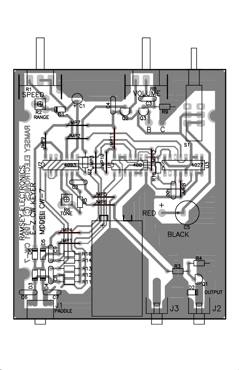
CW7 PARTS LAYOUT DIAGRAM
CW7 • 7
Page 8

KIT BUILDING TIPS:
Use a good soldering technique - let your soldering iron tip gently heat the
traces to which you are soldering, heating both wires and pads simultaneously.
Apply the solder on the iron and the pad when the pad is hot enough to melt the
solder. The finished joint should look like a drop of water on paper, somewhat
soaked in.
Mount all electrical parts on the top side of the board provided, unless otherwise
specified. This is the side that has no traces or pads on it.
Electrical part installation - when parts are installed, the part is placed flat to the
board, and the leads are bent on the backside of the board to prevent the part
from falling out before soldering. The part is then soldered securely to the
board, and the remaining lead length is clipped off.
ASSEMBLY INSTRUCTIONS:
We have a twofold "strategy" for the order of the following kit assembly
steps. First, we install parts in physical relationship to each other, so there's
minimal chance of inserting wires into wrong holes. Second, whenever
possible, we install in an order that fits our "Learn As You Build" Kit-building
philosophy.
FOR EACH PART OUR WORD "INSTALL" ALWAYS MEANS THESE STEPS:
1. Pick the correct part value to start with.
2. Insert it into the correct PC board location.
3. Orient it correctly, which means: Please follow the PC board and
the written directions for all parts where there's a right way and a
wrong way to solder it in. (Diode bands, electrolytic capacitor
polarity, transistor shapes, dotted or notched ends of IC's, and so
forth).
4. Solder all connections unless directed otherwise. Use enough heat
and solder flow for clean, shiny, completed connections. Don't be
afraid of any pen-style soldering iron having enough heat to
damage components.
5. Trim or "nip" excess wire lengths after soldering.
CW7 • 8
Page 9

ASSEMBLY STEPS:
Mark each square as each step is completed.
❒ 1. Install the on-off switch. It fits only one way. Solder all six connections.
The other "pole" DPDT switch may also serve as an operating convenience
for your ham station and can be connected later.
❒ 2. Install the "stereo" (two-circuit) jack for the keyer paddle plug and cord.
❒ 3. Install J2, which connects the keying output of Q1 to the transmitter
keying line. Press the jack firmly until it snaps in flush with the PC-board.
Solder all 4 points.
❒ 4. Install J3 in the same manner as J2. This jack is for your convenience
in ham station set-up and may serve any one of several purposes to be
discussed after assembly is finished.
Installation of the preceding hardware parts places enough "landmarks" on the
PC-board to make further orientation and parts installation proceed more easily.
In the following phase, working from the stereo jack forward, we will install a
majority of the small components required by the CW7 circuit.
IMPORTANT: Notice that the CW7 PC-board requires a total of 12 "jumper
wires", each of which is numbered for easy identification. As you install the
resistors and capacitors in the following steps, save ALL longer bare wire
cuttings from these parts to make sure you have enough jumpers. If you
happen to be short of wire scraps because your kit contains many parts with
pre-formed wire leads, use any bare copper wire of similar diameter to make the
needed jumpers, which are like small "staples" and are inserted, soldered and
trimmed just like resistors.
❒ 5. Near the stereo jack, install C6, .01 uF (marked .01, 103 or 10nF).
❒ 6. Install C7, .01 uF (marked .01 or 103).
❒ 7. Install R11, 100K ohms (brown-black-yellow)
❒ 8. Install R12, 100K ohms (brown-black-yellow)
❒ 9. Install R13, 100K ohms (brown-black-yellow)
❒ 10. Install R14, 330K ohms (orange-orange-yellow)
❒ 11. Install R10, 100K ohms (brown-black-yellow)
❒ 12a.Next to R10, form and install Jumper 1
❒ 12b. Install Jumper 4 next to Jumper 1
CW7 • 9
Page 10

❒ 13a. Install C8, .001 uF (marked .001, 102 or 1nF).
❒ 13b. Install C9, .001 uF (marked .001, 102 or 1nF).
❒ 14. Study the CW7 Parts Layout Diagram and notice the pattern for
orienting the banded (cathode) ends of diodes D3,4,5,6. Inserting all 4
diodes correctly may be a single operation, followed by soldering all 8
connections. Install and solder D3,4,5,6.
❒ 15. Study the design of R6, a 100K miniature potentiometer for adjusting
the pitch of the sidetone oscillator. Insert and solder all three
connections.
❒ 16. Install R5, 10K ohms (brown-black-orange)
❒ 17. Install C2, .1 uF [marked .1 or 104]
❒ 18. Install Jumper 6
❒ 19. Install Jumper 5 (next to Jumper 6).
❒ 20. Install Jumper 10 (at right angle to Jumper 5)
❒ 21. Install Jumper 3 (next to Jumper 10)
❒ 22. Install R7, 1 K ohms (brown-black-red)
PROGRESS SUMMARY
A peek at the circuit diagram shows that we have wired most of the keyerpaddle input circuitry, a part of the sidetone oscillator plus half the jumper
wires needed. Installing the three IC chips, which comes next, will put many
more circuit details in place.
INSTALLING THE IC CHIPS:
The parts already installed should make the locations for all three ICs quite
plain. All three ICs are soldered directly to the PC-board. If you have reasons
for soldering your own DIP IC sockets to the board, feel free to do so,
remembering that such sockets themselves can cause problems. You will
need two 14-pin sockets and one 16-pin socket. The identification of each IC
and the orientation of the "notched" end is made clear on the CW7 Parts
Layout Diagram.
❒ 23. Install U1, type 4001 CMOS IC, in the center position.
❒ 24. Install U2, type 4093, to the left of U1.
❒ 25. Install U3, type 4027 (16 pin) to the right of U1.
❒ 26. Install Jumper 9 near U2.
CW7 • 10
Page 11

❒ 27a.Install Jumper 12 between U1 and U3.
❒ 27b.Install R15, 4.7K (yellow-violet-red) next to Jumper 12
❒ 28. Install C1, 4.7 uF Observe correct polarity.
❒ 29. Install diode D1, making sure that the banded cathode end is oriented
toward R2 as shown.
❒ 30. Install R2, 100K potentiometer
❒ 31. Install Jumper 2
❒ 32. Install Jumper 7
❒ 33. Install Jumper 11 (Only 1 jumper left to go!)
❒ 34a.Install R1, 100K potentiometer
❒ 34b.Install R8, 10K potentiometer
❒ 35. Install C4, .01 uf (marked .01, 103 or 10nF).
❒ 36. Install C3, .1 uF (marked .1 or 104).
❒ 37. Install R9, 1K (brown-black-red)
❒ 38a.Transistors Q2 and Q3 form a simple audio amplifier to provide
speaker- level output from the audio oscillator derived from one section of
the 4093 IC. Observe correct placement of the flat side.
❒ 38b.After studying 38a., install transistor Q2.
❒ 38c.Install transistor Q3 as in the above step.
❒ 39. For now, simply notice the two remaining holes near Q3. These points
are for later connection of wires for a speaker or other audio output.
❒ 40a.THE LAST JUMPER WIRE! Install Jumper 8, and you can save any
remaining wire cuttings for your NEXT project!
❒ 40b.Install C10, .001 uF (marked .001, 102 or 1nF).
❒ 41. Install C5, the larger electrolytic capacitor (100 uF or higher), observing
the correct polarity.
❒ 42. Install the 9-volt battery clip wires, again observing the correct positive
(red) and negative (black) polarity.
❒ 43. Install R3, 1K ( brown-black-red).
❒ 44. Install R4, 10K (brown-black-orange)
❒ 45. Install diode D2, observing correct polarity of the banded cathode end.
CW7 • 11
Page 12

CW7 • 12
Page 13

CW7 • 13
Page 14

❒ 46. Install transistor Q1, Observe correct placement of the flat side. The
output of Q1 is the on-off DC switching which keys your transmitter.
❒ 47. Mount the battery hold-down clamp, using your choice of wire passed
through the PC-board and clamp holes and soldered. With the exception of
dealing with the speaker output connections and possible applications for J3
and the available second pole of S1, the wiring of the CW7 PC-board is now
complete. This would be the best time to review each preceding step,
perhaps adding a check or highlighting mark to each point on the CW7
Parts Layout Diagram as you go back through the assembly directions. It
will take less than 10 minutes and is truly worth doing before applying power
to your new CW7 Electronic Keyer.
BEFORE CONNECTING BATTERY OR TESTING:
❒ 48. To verify correct operation of the CW7 keyer itself as well as the
sidetone oscillator and amplifier circuits, install two hookup wires or 2conductor speaker wire at the two audio output connections near Q3. Use
about 6" of wire connected to any available 8-ohm speaker or
headphones.
❒ 49a.If you already own an electronic keyer paddle, you would probably
know how to use it and connect it. Prepare a cable for your paddle device
terminated in a standard miniature stereo plug.
❒ 49b. If you do not have an electronic keyer paddle, you can either study our
suggestions on making a simple one, or you should at least prepare a
miniature stereo plug and cable set (shielded 2-conductor wire) that will let
you determine that shorting one conductor to the shield makes "dots" and
that the other one makes "dashes".
❒ 50. Since Q1 is a switch designed to turn a transmitter keying circuit on and
off, you need some method of verifying that a connection from J2 does
indeed switch a low voltage circuit on and off. Such a circuit can be:
• A Ramsey QRP transmitter connected to dummy load,
• Battery-powered continuity tester,
• VOM in "ohms" setting,
Or a Test oscillator can be made from Ramsey Mini-Kits UT5 oscillator/timer or
MB1 Mad Blaster.
FIRST TESTS
❒ 1. Review and carry out the procedures suggested in Steps 48, 49 and 50.
❒ 2. With S1 in the "off" position, connect a fresh 9-volt battery.
CW7 • 14
Page 15

❒ 3. Set both front panel controls to their middle positions. After turning on
the switch and becoming satisfied that there is no smoke or heat (yes, a
wrongly-installed part can get VERY hot!), check for the following:
❒ 4. The wires from J1, with or without a paddle, should produce either dots
or dashes, when one or the other is touched to the common (shield) line.
❒ 5. Turning R1 should vary the sending speed.
❒ 6. Turning R8 should vary the speaker volume.
❒ 7. The test circuit connected to J2 should beep, flash or show meter
swings in time with the speaker sounds.
❒ 8. Adjusting trimmer R6 with a small screwdriver should vary the pitch of
the sidetone oscillator.
❒ 9. Adjustment of trimmer R2 is discussed in the next section.
CW7 INITIAL SPEED CONTROL ADJUSTMENT:
The sending speed of the CW7 is controlled by the combination of internal speed
range trimmer R2 and the panel Speed Control, R1. The potential speed range of
the CW7 is virtually unlimited, from 1 or 2 WPM to 50-60 WPM. The higher the
combined resistance of R1 and R2, the slower the speed. Lowering the total
resistance below 20K pushes the speed into impractically high ranges. Raising
the total resistance above 250K ohms makes the lowest keying speed setting
such that the keyer has little use in learning, let alone in on-the-air operation.
You can tinker with R2 to achieve whatever speed range you wish, but the most
practical procedure is as follows:
❒ 1. Set R2 in the approximate center of its total rotation.
❒ 2. Turn R1 fully clockwise (maximum speed).
❒ 3. Begin sending something familiar and repeated such as CQ.
❒ 4. With the small screwdriver in your other hand, adjust R2 until your
sending speed is the maximum that you ever expect to really use, at least for
the time being.
❒ 5. While still sending CQ or your callsign, slowly turn Speed Control R1
counter-clockwise. If you reach the slowest speed you expect to be using
with room to spare, then your adjustment is complete.
"CONFIGURING" YOUR OPTIONS FOR: AUXILIARY J3, AUDIO OUTPUT,
AND EXTRA SWITCH CONTACTS:
There is NO one "best" way to set up the auxiliary functions of an electronic
keyer. That's why some flexibility is pre-designed into your CW7. You can use
and change the possible functions of the audio output, J3 and the SPDT section
CW7 • 15
Page 16

of the power switch without affecting the basic terms of the Ramsey Kit
Warranty or the market value of your CW7.
1. Auxiliary Jack (J3)
This jack does nothing unless you MAKE it do something! Here are some of the
typical ham shack functions to which it may be applied:
Wired in parallel with J1 for:
• connection to 2nd transmitter or transceiver
• input of auxiliary CW straight key
• input of computer CW keying interface
Wired to speaker output connections for:
• external speaker
• connection to external audio amplifier input
Wired to S1 for:
• controlling another DC low-voltage hamshack accessory in
either on or off mode for the keyer itself.
Other applications are easy for both you and us to conceive. There is no need
to do anything with J3 until you decide how it will help you the most.
2. Sidetone Audio Output (2 holes near Q3)
The sidetone may be fed to a small speaker within the CW7 enclosure, to
auxiliary jack J3, through other wiring, or can be simply ignored or not used.
That's right: use it IF you need it, and don't use it if your transceiver already
generates a preferable sidetone. The CW7 sidetone is a convenience option
designed to help beginners enjoy this unit as an upgraded "code practice
oscillator" and to provide sidetone monitoring for Ramsey QRP transmitters. If
you don't need it with your transceiver, don't use it - and you will not hurt our
feelings!
3. Extra SPDT pole on POWER ON-OFF SWITCH
For this switch, a couple of extra PC-board solder pads are provided for the
power-on ("in") position. In addition, the solder connections on the top side of
this switch are all accessible and usable. If you want to turn some other station
accessory on or off when you switch on your CW7 keyer, this switching
convenience is available to you. One practical function is for its second pole to
key your transmitter for tune-up when the keyer power is in the off position.
CW7 • 16
Page 17

"MESSAGE MEMORY" FOR YOUR CW7 KEYER
While there are obviously no built-in memory functions in the CW7, today's
hams do well to recall that "memory keyers" were designed out of necessity by
late 1970's contest enthusiasts, preceding inexpensive personal computers by
several years. There are hundreds of programs, for every operating system,
every programming language and every imaginable computer, which let you
send pre-programmed CW texts of ANY length with one keystroke. So, today,
you can wire the keying outputs of your CW7 for enjoyable hands-on CW
sending, and leaving automated CW texts up to a computer.
TRANSMITTER CONNECTIONS
Transistor Q1 is the high-speed electronic switch which permits the CW7's
circuitry to control an outside device- your transmitter or transceiver. As such, it
is the interface between CW7 logic circuitry and your real-world application.
The CW7 easily and safely controls the low-level DC CW keying inputs of a
wide variety of contemporary amateur radio transceivers as well as most kit and
homebuilt QRP CW transmitters.
HOWEVER, it is up to you to know and understand the CW keying
requirements of your own transmitter or transceiver. Some require a reversed
ground to DC + polarity. Many perfectly-serviceable transmitters from the 1950'
through the 1970's present grid or cathode voltages on the keying line from 60
to 150 volts DC. Such voltages greatly exceed the characteristics of transistor
Q1.
If you have any doubt about or are experiencing problems in keying a ham
transmitter or transceiver with the CW7 keyer, the easiest, cheapest and
quickest solution is to set up your CW7 to key a small SPST relay, either 5VDC
or 12VDC easily available from the selection at Radio Shack stores. "Reed"
relays are ideal for CW operation.
Of course, you can consider the use of higher-power switching transistors, but
that must remain part of the exploration and fun of ham radio, not an essential
detail of this instruction manual. The best "rule" in connecting solid-state keyers
to ham gear is "Know both your transmitter and your keyer, or wire in a modern,
efficient relay!"
If you damage Q1 with a questionable hookup, it is easy and inexpensive to
replace. Radio Shack's ArcherPak No. 276-1617 gives you 15 of them for a few
bucks!
CW7 • 17
Page 18

KEYER "PADDLES" FOR YOUR CW7
Cared for and kept clean, a commercially-built electronic keyer paddle lasts a
lifetime. Because such devices are manufactured in hand-crafted quantities
from machined parts, they carry a price tag to match, about $40 to $100. At
some point in your ham radio life, you'll be able to decide which keyer you like
best. If you're CW communicating, a quality keying paddle can be a very nice
once-and-for-all seasonal gift! Also, keyer paddles are built-in as integral to
some electronic keyers.
Those who offer keyer paddles for sale at hamfest usually know what a new
unit really costs today, so it is rare for them to be available for less than half the
cost of a new one.
The purpose of the following ideas is to give some help to those who have built
the economical CW-7 but who are not ready to choose a keying device more
costly than this kit!
A keyer paddle is basically a momentary SPDT switch that is both comfortable
to handle and mechanically adjustable. As shown in the following two sketches,
it can be in the form of one center lever swung to side contacts, or two levers
"squeezed" to a common center contact. Both styles of keying work fine with
the Ramsey CW7 CMOS Keyer:
Because a keyer paddle is a rather simple device, which can be built from a
wide variety of common hardware items, it is an ideal do-it-yourself project for
SINGLE LEVER
PADDLE
DAH DAH
DIT
“SQUEEZE” PADDLES
CW7 • 18
Page 19

those not ready to pay the price of a Vibroplex or other fine keyer. Over the
years, many dozens of home-made keyers have been described in ham radio
publications.
The basic considerations for any keyer design are:
• A base that will not slide around on the desk.
• Desired paddle lever tension, whether adjustable or fixed.
• Desired contact distance, whether adjustable or fixed.
• Insulation of the three switch points from each other
• Quality of switch contacts
Your keyer will depend on your resources, your patience and your ingenuity.
There is no right or wrong or "more professional" way to make a keyer. If it
helps you to use your electronic keyer to send good, clear CW, then it is a good
keying device. If you have a friend with a machine shop, you can come up with
a design that will rival any commercial unit. If your "contraption" works fine but is
really ugly, you can always enclose it in a matching Ramsey kit case or a
project box from Radio Shack!
Since there are hundreds of conceivable designs using a variety of household
or hardware store items, the most useful thing to do at this point is to review the
above five most basic considerations. Before starting, take time to look at a
working paddle and keyer set-up, so that you fully understand what you want to
design. Our discussions and suggestions will focus on the single-lever style
keyer paddle.
1. THE BASE
Traditionally, keying devices are built on a heavy steel base with rubber feet.
The use of such a metal base also requires some thought on how the three
contact points will be insulated from each other. An alternative to the "heavy"
base is to build your keyer on a plywood or plastic base, securing that base to
your desk after figuring out the most comfortable angle and position.
Aside from going to a metalworking shop to have a steel base cut to your
specifications, you can also make a base by melting lead in a form and then
spray paint it. Lead is easily melted with a propane torch or even on a stove. A
wooden base with hidden cavities for lead filling is another approach.
Only YOU can determine how much bulk weight is needed in your own keyer
paddle device. Rubber feet on a plastic, plywood or PC-board may do just fine
right now. Rubber feet grip even better if they are sitting on a rubber pad of
some sort.
CW7 • 19
Page 20

2. PADDLE LEVER TENSION
Tension is accomplished by springs (or even rubber bands), or by the natural
flexing of the keying lever itself. The classic "simple Keyer" is made from a
piece of hacksaw blade secured at one end, with some style of paddle at the
other. The blade has enough "spring" to it for good, basic electronic keying. An
even easier blade, also giving you a neat, permanently-secured paddle would
be an ordinary steak knife or a stainless-steel kitchen spreader-spatula, with the
excess handle cut off and neatly sanded.
The best way to figure out how you would use a RIGID lever with springs is to
study the designs of working keyers. If you think you may spend as much time
and gas on finding just the right kinds of springs and metal pieces as a good
keyer would cost, then stick with the steak knife idea or buy the keyer.
Common materials used for home-made keying levers include:
A. FLEXIBLE: hacksaw blade, steak knife blade, stainless-steel spatula, strip of
copper-clad (printed circuit) board, small ruler, strip of any metal with some
"spring" to it. A putty knife could be very good too, giving a VERY bold, heavier
handle for forming your paddle.
B. RIGID: (generally about 1/8" thick): The neatest and easiest-to-find steel
pieces would be in the display of L-brackets and mending irons at the hardware
store.
3. CONTACT DISTANCE
The simplest contacts are clean steel or brass screws. Finely-threaded screws
make adjustments easier. While you could start off with fixed contacts, you'll
soon be wishing that you can make small adjustments of the travel distance of
the keying lever. The more comfortable you become with electronic keying, the
closer together you'll want your contacts.
4. INSULATION OF THE SWITCH CONTACTS
Think of this requirement as you design your keyer from the base up. The three
contacts must come into contact only when you want them to: that's what a
keyer IS! Plastic or dry, finished wood can serve the purpose. The dryness of
the wood used IS important, because even a damp finger can key the input of a
sensitive keyer such as the CW-7.
5. THE SWITCH CONTACTS
Commercial keyers use silver switch contacts, primarily because it is expected
by customers paying good money for the keyer. Silver or even gold are the
"traditional" materials for "fine" electrical contacts. In the case of a simple keyer,
this can be much to do about nothing. In fact, silver's tendency to tarnish poses
quite a problem for modern solid state keyers. Shiny screws kept clean with an
emery board will work fine.
CW7 • 20
Page 21

A QUICK AND EASY PADDLE FOR THE CW-7 KEYER
The preceding ideas should be enough to give you plenty of thoughts on how to
make a keyer or whether you prefer to purchase one. In the meantime, the
fastest, cheapest and still a fairly neat way of making a simple, adjustable
paddle is shown below:
Materials Needed for Simple Keyer Paddle:
1- stainless steel spatula or steak knife
4- small "L" brackets (1" or smaller)
4- 8-32 X 1/2" machine screws
6- 8-32 nuts
4- small wood or sheet metal screws
1- 1/4" plywood base, cut to 4X5" (approx.), sanded, finished
4- small, non skid rubber feet
1- stereo headphone cord and plug to mate CW-7 jack
CW7 • 21
Page 22

Basic Key Assembly:
Two of the L-brackets are used to hold the tip of the knife, so that it will not
slip up and down. Two nuts are used on the "dit and dah" side contact
screws so that adjustments can be made and held. The knife handle is cut
down to whatever length you like. It's a good idea to tin the three wires with
solder before securing them under the three L-bracket screws. The bladelever "travels" most near the handle and least near the bracket, which may
help you decide exactly where to mount the two contact brackets. A quality
sharp drill bit will be needed to make the two holes required in the end of the
stainless steel blade. The contact screws will be much easier to adjust if you
have knowhow to braze or solder one machine nut to each of the contact
brackets.
FINAL NOTE ON "KEYING YOUR KEYER"
The basic styling of a keyer paddle, requiring back-and-forth wrist action is
merely an unquestioned telegraphy "tradition"- the design of keyer paddles
is basically a modification of the famous "semi-automatic" mechanical keys
called "bugs". This is a fine way to enjoy CW as a clear communications
language, but don't hesitate to try out other ways of controlling the output of
your CW7 keyer. You might like tapping two fingers on two sensitive pushbuttons, or making a keyer out of small micro-switches, or keying with a
finger from each hand, and so forth. If you find some "alternative key" to be
comfortable and enjoyable for you, then DO IT! Such alternatives to "wrist-nfist" ways of generating coherent CW communications are espescially vital
for mobile, cycling and other ham-travel applications. Attention to such
alternative keying systems is of great value to researching techniques for
handicapped persons.
Just as there is no law that says we must master "brass pounding"
semaphore flags or smoke signals, there's no rule that states that electronic
keyers MUST be controlled by traditional "paddles".
"CW" today is simply an efficient international human language. HOW you
make it sound good and clear is YOUR business and your challenge! As you
discover newer techniques for "speaking the language", be sure to share
your ideas with other hams. Thank you for your interest in the economical
Ramsey CW7 CMOS Keyer.
If you've enjoyed building this Ramsey kit, there're plenty more to enjoy! Call
or write for our free catalog.
CW7 • 22
Page 23

The Ramsey Kit Warranty
Please read carefully BEFORE calling or writing in about your kit. Most problems can be
solved without contacting the factory.
Notice that this is not a "fine print" warranty. We want you to understand your rights and ours too! All
Ramsey kits will work if assembled properly. The very fact that your kit includes this new manual is your
assurance that a team of knowledgeable people have field-tested several "copies" of this kit straight from
the Ramsey Inventory. If you need help, please read through your manual carefully, all information
required to properly build and test your kit is contained within the pages!
1. DEFECTIVE PARTS: It's always easy to blame a part for a problem in your kit, Before you conclude
that a part may be bad, thoroughly check your work. Today's semiconductors and passive components
have reached incredibly high reliability levels, and it’s sad to say that our human construction skills have
not! But on rare occasions a sour component can slip through. All our kit parts carry the Ramsey
Electronics Warranty that they are free from defects for a full ninety (90) days from the date of purchase.
Defective parts will be replaced promptly at our expense. If you suspect any part to be defective, please
mail it to our factory for testing and replacement. Please send only the defective part(s), not the entire kit.
The part(s) MUST be returned to us in suitable condition for testing. Please be aware that testing can
usually determine if the part was truly defective or damaged by assembly or usage. Don't be afraid of
telling us that you 'blew-it', we're all human and in most cases, replacement parts are very reasonably
priced.
2. MISSING PARTS: Before assuming a part value is incorrect, check the parts listing carefully to see if it
is a critical value such as a specific coil or IC, or whether a RANGE of values is suitable (such as "100 to
500 uF"). Often times, common sense will solve a mysterious missing part problem. If you're missing five
10K ohm resistors and received five extra 1K resistors, you can pretty much be assured that the '1K ohm'
resistors are actually the 'missing' 10 K parts. Ramsey Electronics project kits are packed with pride in the
USA. If you believe we packed an incorrect part or omitted a part clearly indicated in your assembly
manual as supplied with the basic kit by Ramsey, please write or call us with information on the part you
need and proof of kit purchase
3. FACTORY REPAIR OF ASSEMBLED KITS: To qualify for Ramsey Electronics factory repair, kits
MUST:
1. NOT be assembled with acid core solder or flux.
2. NOT be modified in any manner.
3. BE returned in fully-assembled form, not partially assembled.
4. BE accompanied by the proper repair fee. No repair will be undertaken until we have received
the MINIMUM repair fee (1/2 hour labor) of $25.00, or authorization to charge it to your credit card
account.
5. INCLUDE a description of the problem and legible return address. DO NOT send a separate
letter; include all correspondence with the unit. Please do not include your own hardware such as
non-Ramsey cabinets, knobs, cables, external battery packs and the like. Ramsey Electronics,
Inc., reserves the right to refuse repair on ANY item in which we find excessive problems or
damage due to construction methods. To assist customers in such situations, Ramsey
Electronics, Inc., reserves the right to solve their needs on a case-by-case basis.
The repair is $50.00 per hour, regardless of the cost of the kit. Please understand that our technicians are
not volunteers and that set-up, testing, diagnosis, repair and repacking and paperwork can take nearly an
hour of paid employee time on even a simple kit. Of course, if we find that a part was defective in
manufacture, there will be no charge to repair your kit (But please realize that our technicians know the
difference between a defective part and parts burned out or damaged through improper use or assembly).
4. REFUNDS: You are given ten (10) days to examine our products. If you are not satisfied, you may
return your unassembled kit with all the parts and instructions and proof of purchase to the factory for a full
refund. The return package should be packed securely. Insurance is recommended. Please do not cause
needless delays, read all information carefully.
CW7 • 23
Page 24

CW7 CW KEYER KIT
Quick Reference Page Guide
Introduction to the CW7 ..................4
Parts list for the CW7 .....................6
Parts layout diagram .......................7
Assembly instructions. ....................8
Schematic diagram .......................12
Initial testing ..................................15
Adding options ..............................16
Transmitter connections ...............17
Paddle information ........................18
Making your own paddle ...............19
Warranty .......................................23
REQUIRED TOOLS
• Soldering Iron (WLC100)
• Thin Rosin Core Solder (RTS12)
• Needle Nose Pliers (MPP4 or RTS05)
• Small Diagonal Cutters (RTS04)
ADDITIONAL SUGGESTED ITEMS
• Helping Hands Holder for PC Board/Parts
(HH3)
• Technician’s Tool Kit (TK405)
• Desoldering Braid (RTS08)
TOTAL SOLDER POINTS
180
ESTIMATED ASSEMBLY
TIME
Beginner .............. 4.5 hrs
Intermediate ........ 3.0 hrs
Advanced ............. 2.0 hrs
Price: $5.00
Ramsey Publication No. CW7
Assembly and Instruction manual for: CW KEYER KIT
RAMSEY MODEL NO. CW7 CMOS CW KEYER
RAMSEY ELECTRONICS, INC.
590 Fishers Station Drive
Victor, New York 14564
Phone (585) 924-4560
Fax (585) 924-4555
www.ramseykits.com
CW7 • 24
 Loading...