

Page 1

CODE PRACTICE
OSCILLATOR KIT
Ramsey Electronics Model No. CPO3
Ever wanted to hone your code skill but didn’t have an easy
way to practice? This handy little kit will allow you to tap away
anywhere you happen to be! Small enough to fit into your
pocket or briefcase, you can take it anywhere. You’ll find
yourself up to speed in no time!
• Great starter kit
• Ideal for Boy Scouts
• Perfect first electronic kit for schools
• Increase your code speed . . . practice anywhere.
• Easy one evening assembly
CPO3 • 1
Page 2

PARTIAL LIST OF AVAILABLE KITS
RAMSEY TRANSMITTER KITS
• FM10A FM Stereo Transmitter
• FM25B Synthesized FM Stereo Transmitter
• AM25 Synthesized AM Transmitter
• AM1 AM Transmitter
RAMSEY RECEIVER KITS
• FR1 FM Broadcast Receiver
• AR1 Aircraft Band Receiver
• AA7 Active Antenna
• SC1 Shortwave Converter
RAMSEY HOBBY KITS
• SG7 Personal Speed Radar
• SS70 Speech Scrambler
• TT1 Telephone Recorder
• SP1 Speakerphone
• MD3 Microwave Motion Detector
• PH10 Peak hold Meter
• LC1 Inductance-Capacitance Meter
RAMSEY AMATEUR RADIO KITS
• DDF1 Doppler Direction Finder Kit
• HR Series HF All Mode Receivers
• QRP Series HF CW Transmitters
• CW7 CW Keyer
• QRP Power Amplifiers
RAMSEY MINI-KITS
Many other kits are available for hobby, school, scouts and just plain FUN. New
kits are always under development. Write or call for our free Ramsey catalog.
CODE PRACTICE OSCILLATOR KIT INSTRUCTION MANUAL
Ramsey Electronics publication No. MCPO3 Revision
COPYRIGHT
14564. All rights reserved. No portion of this publication may be copied or duplicated without the
written permission of Ramsey Electronics, Inc. Printed in the United States of America.
1994 by Ramsey Electronics, Inc. 590 Fishers Station Drive, Victor, New York
First printing: January 2001
CPO3 • 2
Page 3

Ramsey Publication No. MCPO3
Manual Price Only $5.00
INSTRUCTION MANUAL FOR
CODE PRACTICE
OSCILLATOR KIT
TABLE OF CONTENTS
Introduction .................................... 4
Circuit Description .......................... 4
Schematic Diagram ........................ 5
Parts Layout Diagram .................... 5
Parts List ........................................ 6
Identifying Kit Parts ........................ 7
International Morse Code ............... 8
Assembly Instructions .................. 12
Testing ......................................... 14
Conclusion ................................... 14
Ramsey Kit Warranty ................... 15
CPO3 • 3
RAMSEY ELECTRONICS, INC.
590 Fishers Station Drive
Victor, New York 14564
Phone (585) 924-4560
Fax (585) 924-4555
www.ramseyelectronics.com
Page 4

INTRODUCTION
Morse Code has been used since 1837. It was originally used for telegraph
communications and was the first method used for radio communications.
For many years, Morse Code was required knowledge for any shipboard
radio operator. In 1910, the Titanic was the first ship to use the international
distress call SOS. Until recently, code proficiency was required for all
amateur radio licensees and was even required by the Boy Scouts. It still is
required for the Signaling merit badge. The CPO3 is a fun, educational kit for
any skill level builder and can be used to introduce anyone to this historic
means of communication.
CIRCUIT DESCRIPTION
As the key is pressed, providing the circuit a ground path and starting the
cycle, two things happen. C1 starts to charge via R1, R3 and R4. At this time
the output of pin 3 is high. When the voltage on C1 reaches 2/3 of the supply
voltage, the output of pin 3 will go low and pin 7 is grounded, starting the
discharge cycle. The capacitor is discharged through R1. When the voltage
on C1 reaches 1/3 of the supply voltage, the output at pin 3 goes high and
pin 7 is no longer at ground. This starts the charging cycle again.
Timing is completely independent of the supply voltage used. It is determined
by the values R1, R3, R4 and C1. The formula for the total time (T) of a
complete cycle is:
T = 0.693[(R3+R4+2R1)C1].
The component values provided allow a range of 1300 Hz to 1700 Hz. The
key is attached to pin 1 and provides the kit with a ground connection,
completing the circuit and turning the entire unit on. The key is basically an
on/off switch. Capacitor C2 filters out noise and R2 is a current limiting
resistor for the speaker, SP1.
CPO3 • 4
Page 5
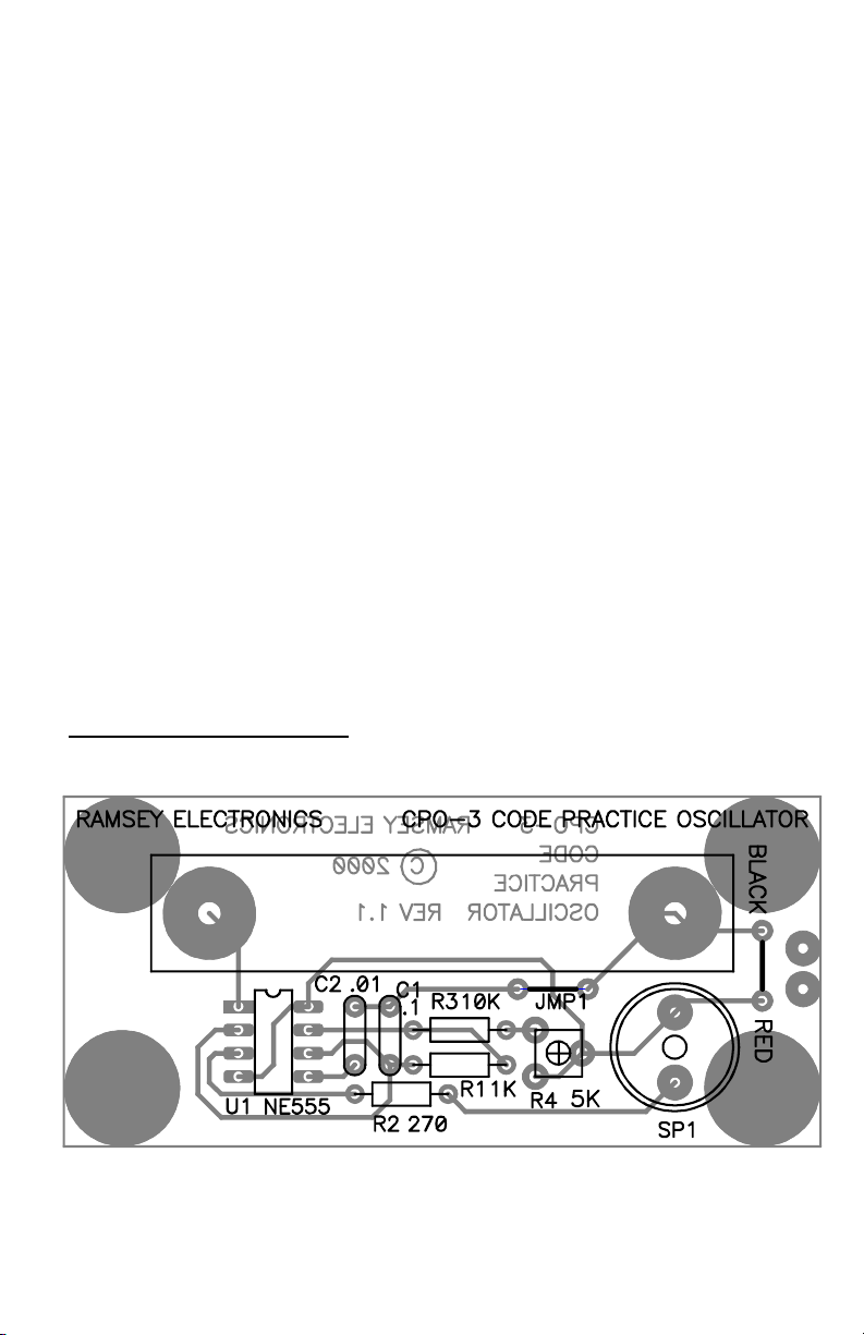
PARTS LAYOUT DIAGRAM
CPO3 • 5
Page 6

PARTS LIST
RESISTORS
1 270 ohm resistor [red-violet-brown] (R2)
1 1K ohm resistor [brown-black-red] (R1)
1 10K ohm resistor [brown-black-orange] (R3)
1 5K ohm trim pot [marked 502] (R4)
CAPACITORS
1 .1 µF ceramic disc capacitor [marked .1 or 104 or 100 nF] (C1)
1 .01 µF ceramic disc capacitor [marked .01, 103, or 10nF] (C2)
SEMICONDUCTORS
1 NE555 timer/oscillator chip (U1)
HARDWARE AND MISCELLANEOUS
1 mini speaker (SP1)
1 9 volt battery snap
1 brass strip
1 #4 flat washer
2 4-40 x 1/4 machine screws
2 4-40 kepnuts
4 rubber feet
CPO3 • 6
Page 7

SORTING PARTS AND GETTING READY!
Prepare a clear, uncluttered workspace. In addition to room needed for tools
and handling the circuit board, allow space for some kind of “parts organizer”
that will not be bumped or dropped. This organizer can be a small tray or
box. (An egg crate works great!)
Refer to the Parts List published in the kit manual. Organize the kit parts
according to basic types. Check carefully to make sure a small part did not
slip away when opening the kit's packaging.
Please make sure that you have sufficient lighting for clear parts
identification and accurate circuit soldering. This might seem like gratuitous
advice that you did not ask for, but experience has shown that brown,
orange, red and silver resistor colors and tiny numbers on capacitors and
transistors all start to look the same in dim light after a hard day's work!
IDENTIFYING KIT PARTS
CERAMIC DISC CAPACITORS
It is helpful practice to become as familiar as possible with the various
marking codes for ceramic capacitors. The first fact to keep in mind is that
there are several accepted methods for marking the value of these
capacitors! While resistor color codes have withstood changing times over
many decades, the protocols for marking evermore tiny capacitors have
many variations!
While capacitors also can be color-coded, Ramsey Kits use disc capacitors
marked by a number/letter code. The first two digits establish the first two
numbers of the value. The third digit is the multiplier. The letter designates
the manufacturing 'tolerance"or accuracy for the value printed.
Values under 100 picofarads, used widely in our FM and VHF kits, are
printed clearly with no need to interpret them further. Small capacitors
stamped 4.7, 10, 15, 33, 68 and so forth are 4.7, 10, 15, 33, 68 picofarads
respectively! A 100 picofarad capacitor, also commonly used in our kits, can
be marked either 100 or 101! If it's marked 100, believe it. If it is marked
101, the value is 10 (first 2 digits) X 10 (3rd digit multiplier) = 100 picofarads!
If it is marked 101J, we know that it is made to 5% accuracy, while H
signifies 3% and K is 10%.
Rule of thumb: If the 3rd digit is a 0, you may assume the value is in
picofarads, and you can take the three numbers together as the picofarad
value for that capacitor. So, just as in the above example, both “470” and
“471” are 470 pf.
CPO3 • 7
Page 8

INTERNATIONAL MORSE CODE
CPO3 • 8
Page 9

CPO3 • 9
Page 10

There is a growing trend to mark capacitors very clearly in nanofarads. Be
sure not to confuse 10nf or 100nf with 10 or 100 picofarads!
There's more! Some manufacturers don't care about codes and print the
value and tolerance VERY plainly. E.g.,. “820+20%” means 820 pf. at 20%
tolerance. Yet another style of capacitor for values such as .1 uf is
manufactured as a neat, rectangular block, with the value and other
identifying data stamped on the top. For example, the information of interest
to you in the marking “.1J63” on such a capacitor is the “.1” for .1 uf.
RESISTORS
The universal color coding of resistors does not change, fortunately, but
resistor body colors and the style of wire leads can vary. Also, resistors may
be packed loose or supplied on tape strips. Install any resistor as shown on
the PC board parts layout diagram. Keep all leads as short as possible.
4 Band Code
COLOR 1st BAND 2nd BAND 3rd BAND MULTIPLIER TOLERANCE
Black 0 0 0 1 ohm
Brown 1 1 1 10 ohms +/- 1% (F)
Red 2 2 2 100 ohms +/-2% (G)
Orange 3 3 3 1K ohm
Yellow 4 4 4 10K ohm
Green 5 5 5 100K ohm +/-0.5% (D)
Blue 6 6 6 1M ohm +/-0.25% (C)
Violet 7 7 7 +/-0.10% (B)
Gray 8 8 8 +/-0.05%
White 9 9 9
Gold 0.1 +/- 5% (J)
Silver 0.01 +/- 10% (K)
5 Band Code
CPO3 • 10
Page 11

BOARD SOLDERING
Unprofessional soldering practices are the nightmare of ANY electronics
manufacturer or service shop. GOOD soldering is essential to the
performance of your project. A “cold” solder connection is caused by too
little heat OR by heating only the component wire and not the wire and PC
copper foil together. The tell-tale sign of too little heat is a dull, rough-looking
connection. If you heat only the wire, the solder forms a cute ball around the
wire, and rosin may completely insulate your ball from the copper.
SOLDER BRIDGES
You probably know that a solder bridge is a perfect and unintended
connection of two PC board points that should NOT be connected. They
happen most easily when soldering IC's and other devices with pins close
together. The only technique for avoiding solder bridges is for you to be in
complete control of the tip of your soldering pencil. The best single tools for
avoiding bridges are a proper point on the soldering iron, bright light,
perhaps with some magnification of your work, and thin diameter solder.
Study your connection before you zap it with heat and solder. Choose the
best “approach angle” for the iron's tip to heat the connection. Plan ahead to
let your solder do what YOU want it to do, and you just won't make any
solder bridges!
TEN COMMANDMENTS OF GOOD PC-BOARD SOLDERING
1. If the soldering iron tip is covered with burned rosin, it cannot heat your
connection very well.
2. If you heat only the wire and not the wire and PC trace together, a cold,
bad connection is likely.
3. If your soldering tip is big enough to bridge two adjoining connections, it
probably will!
4. Dirty, grubby solder will contribute to dirty, grubby connections.
5. Any use of acid core (plumbers!) solder in electronics work will destroy
everything...DON’T USE IT!
6. A connection in a large area of PC-board copper requires more heat
than one pin of an IC.
7. If your connection looks dull or brittle, it's no good.
8. If your connection looks like a ball instead of a shiny cone, it's no good.
9. Thin diameters of shiny, fresh rosin core solder are easier to use for KIT
PC board work than thicker “hardware store” solder.
10. Pre-tin any stranded hookup wires leading in and out of your PC board
kit project. It will prevent problems later!
CPO3 • 11
Page 12

ASSEMBLY INSTRUCTIONS
In ALL PC board assembly steps, our word "INSTALL" means to do this:
• Insert the part, oriented or "pointed" correctly, into its holes in the PC
board.
• If helpful, gently BEND the part's wire leads or tabs to hold it in place,
with the body of the part snugly against the top side ("component side")
of the circuit board. The “component side” is silkscreened with the part
numbers for easy parts location identification.
• Solder ALL wires or pins of the part.
• Trim or "nip" all excess wire lengths extending beyond each solder
connection, taking care that wire trimmings do not become lodged in
solder connections.
• Follow the assembly instructions IN SEQUENCE and check off each
step as understood and completed. Examine the schematic circuit
diagram and PC Board parts layout diagram as you proceed.
• Use good soldering techniques! Let your soldering iron tip heat both the
component lead wire and PC board trace enough so that the wire itself
AND the foil trace BOTH become hot enough TOGETHER to melt a bit
of solder so that it flows smoothly from the pin to the PC board trace.
Enough said... Let’s get building!
As you build your code practice oscillator kit, save a couple of clipped off
leads from capacitors and resistors. These will be needed later. If you throw
out your lead scraps you’ll have to find buss wire to make these important
connections.
1. Install U1, the NE555 timer/oscillator IC. To ensure that the part is
seated flat on the PC board, mount the part and place the circuit board
component side down on the table top before soldering the leads. This
will keep the IC from moving while you solder it. Solder all 8 pins.
2. Install C2, .01 µF ceramic disc capacitor (marked .01, 103, or 10nF).
3. Install C1, .1 µF ceramic disc capacitor (marked .1 or 104 or 100nF).
4. Install R3, 10K ohm (brown-black-orange).
5. Install R1, 1K ohm (brown-black-red).
6. Install R2, 270 ohm (red-violet-brown).
7. You will now need to install a jumper wire, JMP 1. Take one of your
saved leads and form it into what looks like a staple whose width
CPO3 • 12
Page 13

corresponds to the hole spacing on the board marked JMP 1. Once
formed, install the wire just as if it were a resistor, bend the leads out on
the solder side of the board to keep it from falling out, and solder.
8. Install R4, 5K ohm trimpot (502).
9. Install the mini speaker, SP1. Seat it flat on the PC board before
soldering.
10. Install the 9 volt battery snap. You’ll notice that the PC board is
marked BLACK and RED on one end. This is the location of the battery
snap connector. Once you have the wires soldered, use the other set of
holes and another clipped off lead bent into a loop to hold down the wires.
Bend on the back and solder into place. Be careful not to hold the iron on
the joints so long that you melt the insulation on the wires.
11. Now we’re on to the more mechanical part of the CPO3. It’s time to
install the “key”. First, take one of the 4-40 screws and 4-40 kepnuts, plus
the one #4 washer. These fit in the large hole on the PC board under the
words “Ramsey Electronics”. Place the washer on the screw and insert
through the top side of the board, then attach the kepnut to the bottom
and tighten.
12. Next, take the brass strip and line the hole up with the other hole in
the PC board. Place the screw through the brass strip, then the board and
attach the kepnut on the bottom.
13. The brass strip should be touching the screw on the opposite end and
needs to be bent up slightly to form your key. Just bend the brass up
enough that it is not touching the other screw; too much of a bend will
make the key harder to push down to make contact. Keep in mind that it is
easier to bend the strip a little more than to try to “unbend” it.
14. Stick the four rubber feet on the bottom side of the board on the four
corners. The silkscreen shows the correct position of the feet.
That’s it! You’re done building your code practice oscillator. Before snapping a
battery into place give the kit a good lookover. Check for good, clean solder
joints and be sure there are no wire scraps lodged between components or
traces.
CPO3 • 13
Page 14

TESTING
• Attach a 9 volt battery to the battery snap.
• Try your CPO3 by pressing down on the brass strip. You should hear the
audio tone from the speaker.
• Vary the audio tone by turning the adjustment in R4, the trimpot until you
get your desired “pleasing” tone.
• Look up the Morse Code table in centerfold of this manual and get
practicing!
CONCLUSION
We sincerely hope that you will enjoy the use of this Ramsey product. As
always, we have tried to compose our manual in the easiest, most “user
friendly” format that is possible. As our customers, we value your opinions,
comments, and additions that you would like to see in future publications.
Please submit comments or ideas to:
Ramsey Electronics Inc.
Attn. Hobby Kit Department
590 Fishers Station Drive
Victor, NY 14564
And once again, thanks from the folks at Ramsey!
CPO3 • 14
Page 15

The Ramsey Kit Warranty
Please read carefully BEFORE calling or writing in about your kit. Most problems can be solved
without contacting the factory.
Notice that this is not a "fine print" warranty. We want you to understand your rights and ours too! All
Ramsey kits will work if assembled properly. The very fact that your kit includes this new manual is
your assurance that a team of knowledgeable people have field-tested several "copies" of this kit
straight from the Ramsey Inventory. If you need help, please read through your manual carefully, all
information required to properly build and test your kit is contained within the pages!
1. DEFECTIVE PARTS: It's always easy to blame a part for a problem in your kit, Before you conclude
that a part may be bad, thoroughly check your work. Today's semiconductors and passive components
have reached incredibly high reliability levels, and it’s sad to say that our human construction skills
have not! But on rare occasions a sour component can slip through. All our kit parts carry the Ramsey
Electronics Warranty that they are free from defects for a full ninety (90) days from the date of
purchase. Defective parts will be replaced promptly at our expense. If you suspect any part to be
defective, please mail it to our factory for testing and replacement. Please send only the defective part
(s), not the entire kit. The part(s) MUST be returned to us in suitable condition for testing. Please be
aware that testing can usually determine if the part was truly defective or damaged by assembly or
usage. Don't be afraid of telling us that you 'blew-it', we're all human and in most cases, replacement
parts are very reasonably priced.
2. MISSING PARTS: Before assuming a part value is incorrect, check the parts listing carefully to see
if it is a critical value such as a specific coil or IC, or whether a RANGE of values is suitable (such as
"100 to 500 uF"). Often times, common sense will solve a mysterious missing part problem. If you're
missing five 10K ohm resistors and received five extra 1K resistors, you can pretty much be assured
that the '1K ohm' resistors are actually the 'missing' 10 K parts ("Hum-m-m, I guess the 'red' band really
does look orange!") Ramsey Electronics project kits are packed with pride in the USA. If you believe
we packed an incorrect part or omitted a part clearly indicated in your assembly manual as supplied
with the basic kit by Ramsey, please write or call us with information on the part you need and proof of
kit purchase
3. FACTORY REPAIR OF ASSEMBLED KITS:
To qualify for Ramsey Electronics factory repair, kits MUST:
1. NOT be assembled with acid core solder or flux.
2. NOT be modified in any manner.
3. BE returned in fully-assembled form, not partially assembled.
4. BE accompanied by the proper repair fee. No repair will be undertaken until we have received the
MINIMUM repair fee (1/2 hour labor) of $18.00, or authorization to charge it to your credit card
account.
5. INCLUDE a description of the problem and legible return address. DO NOT send a separate letter;
include all correspondence with the unit. Please do not include your own hardware such as
non-Ramsey cabinets, knobs, cables, external battery packs and the like. Ramsey
Electronics, Inc., reserves the right to refuse repair on ANY item in which we find excessive
problems or damage due to construction methods. To assist customers in such situations,
Ramsey Electronics, Inc., reserves the right to solve their needs on a case-by-case basis.
The repair is $36.00 per hour, regardless of the cost of the kit. Please understand that our technicians
are not volunteers and that set-up, testing, diagnosis, repair and repacking and paperwork can take
nearly an hour of paid employee time on even a simple kit. Of course, if we find that a part was
defective in manufacture, there will be no charge to repair your kit (But please realize that our
technicians know the difference between a defective part and parts burned out or damaged through
improper use or assembly).
4. REFUNDS: You are given ten (10) days to examine our products. If you are not satisfied, you may
return your unassembled kit with all the parts and instructions and proof of purchase to the factory for a
full refund. The return package should be packed securely. Insurance is recommended. Please do not
cause needless delays, read all information carefully.
CPO3 • 15
Page 16

CPO3 CODE PRACTICE OSCILLATOR KIT
Quick Reference Page Guide
Circuit Description .......................... 4
Schematic Diagram ........................ 5
Parts Layout Diagram .................... 5
Assembly Instructions .................. 12
Ramsey Kit Warranty ................... 15
REQUIRED TOOLS
• Soldering Iron (WLC100)
• Thin Rosin Core Solder (RTS12)
• Needle Nose Pliers (MPP4 or RTS05)
• Small Diagonal Cutters (RTS04)
ADDITIONAL SUGGESTED ITEMS
• Helping Hands Holder for PC Board/Parts (HH3)
• Technician’s Tool Kit (TK405)
• Desoldering Braid (RTS08)
Manual Price Only: $5.00
Ramsey Publication No. MCPO3
Assembly and Instruction manual for:
RAMSEY MODEL NO. CPO3 CODE PRACTICE OSCILLATOR
TOTAL SOLDER POINTS
29
RAMSEY ELECTRONICS, INC.
590 Fishers Station Drive
Victor, New York 14564
Phone (585) 924-4560
Fax (585) 924-4555
www.ramseyelectronics.com
CPO3 • 16
ESTIMATED ASSEMBLY
TIME
Beginner ............... 1 hr
Intermediate ......... .0.75 hrs
Advanced .............0.5 hrs
 Loading...