

Page 1
INSTALLATION AND OPERATING
INSTRUCTIONS FOR RAMSEY
UNIVERSAL WIRELESS REMOTE
CONTROL FOR ATV WINCHES
KIT #’S 251203, 251204,
251205, & 251206
Warnings
1. THE RAMSEY UNIVERSAL WIRELESS REMOTE FOR ATV WINCHES IS
DESIGNED FOR USE ON SELF
-RECOVERY WINCHES ONLY. THE REMOTE IS
NOT DESIGNED FOR AND SHOULD NOT BE USED ON WINCHES OR HOISTS IN
INDUSTRIAL APPLICATIONS
(CAR HAULERS/CARRIERS, WRECKERS, CRANES,
ETC.) OR FOR ANY OTHER REMOTE CONTROLLED APPLICATION.
2. W
HEN REELING IN CABLE UNDER NO LOAD, RELEASE THE REMOTE BUTTON
WHEN THE HOOK IS A MINIMUM OF
3 FT (1 M) FROM THE WINCH FAIR-
LEAD. CAREFULLY JOG THE REMOTE CONTROL BUTTON UNTIL THE HOOK IS A
MINIMUM OF
1 FT (.3M) FROM THE FAIR-LEAD. DISENGAGE THE CLUTCH
AND FINISH SPOOLING IN CABLE BY ROTATING THE DRUM BY HAND
.
3. When finished winching, turn transmitter off.
4. Do not pressure wash or steam clean the receiver. This can damage the receiver and adversely affect operation.
5. Refer to winch owner’s manual for all winch operating instructions and warnings.
The following are general installation instructions. Actual
installation may vary depending on the ATV manufacturer
and model.
Page 2

251203 SUPERWINCH ATV 2000 & T 1500
Parts List ........................................................ 1
Before Beginning Installation ............................2
Installing the Kit ...............................................2-4
Electrical Schematic ........................................5
Testing & Operation of Remote ........................6
Troubleshooting Guide......................................21
251204 WARN A2000,
SUPERWINCH X1, X2, X1F, X2F, EX1
Parts List ........................................................ 7
Before Beginning Installation ........................... 8
Installing the Kit .............................................. 8-10
Electrical Schematic ........................................11
Testing & Operation of Remote ........................12
Troubleshooting Guide......................................21
251205 WARN A2500
Parts List ........................................................ 13
Before Beginning Installation ............................14
Installing the Kit .............................................. 14-15
Electrical Schematic.........................................15
Testing & Operation of Remote ........................16
Troubleshooting Guide......................................21
251206 SUPERWINCH X1, X2, X1F, X2F, EX1
(WITH HAND HELD REMOTE)
Parts List ........................................................ 17
Before Beginning Installation ............................18
Installing the Kit .............................................. 18-19
Electrical Schematic.........................................19
Testing & Operation of Remote ........................20
Troubleshooting Guide......................................21
Page 3
1
251203 SUPERWINCH ATV 2000 & T 1500
ITEM
NO.
1
2
3
4
5
6
7
8
9
10
11
12
13
14
15
QTY.
1
1
1
1
1
2
2
2
1
1
2
1
4
3
1
PART
NO.
282058
251198
251234
251190
*
416227
418140
440125
251235
440274
DESCRIPTION
WIRELESS RECEIVER & TRANSMITTER KIT
DIPOLE ANTENNA KIT
SOLENOID KIT
REPLACEMENT TRANSMITTER
REPLACEMENT BATTERY
SCREW #10-24 X 3/4 TRUSS F/B
NUT #10-24 HEX LOCK
FLAT WASHER #10 Z/P
WIRE SPLICE
TOGGLE SWITCH
TUBE CLAMP
CABLE TIES
RING TERMINALS
RUBBER BOOT
WIRING HARNESS
* SONY CR2032 OR DURACELL DL2032
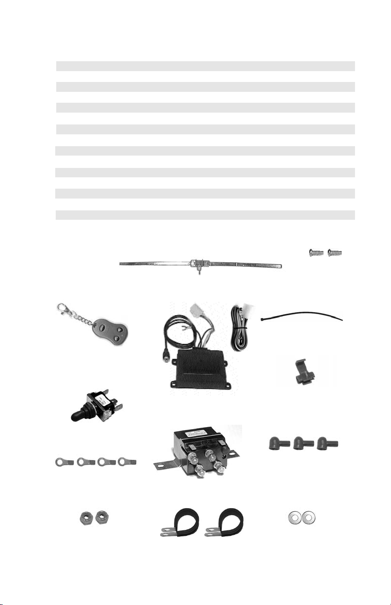
REMOTE RECEIVER
CABLE TIE
ANTENNA
MOUNTING
SCREWS
REMOTE
TRANSMITTER
SOLENOID
TOGGLE SWITCH
RING TERMINALS
TUBE CLAMP
WIRE SPLICE
FLATWASHERS
LOCK NUTS
RUBBER BOOT
Page 4

251203 SUPERWINCH ATV 2000 & T 1500
Before Beginning Installation
1. Disconnect power lead from winch to battery.
2. Disengage winch clutch.
3. Remove hood or cowling as necessary for easier access to installation area.
4. Locate & mark mounting locations for receiver, toggle switch, solenoid
assembly, & antenna.
NOTE:
Make sure locations are close enough for wiring connections to be
made without making alterations to wire lengths. Solenoid assembly
will be mounted to tube frame of ATV using supplied tube clamps,
except for Polaris models which mount directly to the ATV crossmember under hood, using supplied mounting screws.
Antenna will need a space of at least 15” wide under cowling or hood
for mounting in the horizontal configuration required for best reception. Antenna is flexible and will follow the contour of the cowling or
hood. The antenna should be mounted at least 10” from winch motor
and battery leads.
Installing the Receiver
1. Insert plastic tie through mounting ears on receiver and secure receiver to
location determined above.
2. Tighten plastic tie and clip excess.
3. Attach ground wire to ATV frame.
CAUTION: Do not alter the length of the ground wire as this will affect
performance of the remote.
4. Attach wiring harness to receiver & route yellow and green wires to solenoid
location.
Installing the Ring Terminals
1. Remove rocker switch assembly from handlebar.
2. Disconnect wires from rocker switch.
3. Cut spade terminals off ends of battery and motor leads.
4. Slip rubber boots over ends of wires and install supplied ring terminals in
place of spade connectors.
5. Route wires to location where solenoid will be mounted.
2
Page 5

NOTE: For clarification see wiring schematic on page 5.
1. Attach black with yellow stripe motor lead to lower right terminal stud
“B” on solenoid.
2. Attach black motor lead to lower left terminal stud “C” on solenoid.
3. Attach connector with 2 yellow wires to the terminal directly above the
black with yellow stripe motor lead.
4. Attach connector with 2 green wires to the terminal directly above the
black motor lead.
5. Attach black battery lead to upper left terminal stud “E” on solenoid.
6. Attach red battery lead to upper right stud “A” on solenoid.
Connecting Wiring to Solenoids
Installing the Solenoid
1. Mount solenoid in location determined previously.
2. Secure using (1) tube clamp, (1) #10-24 screw, (1) flat washer, and (1)
lock nut each side of solenoid assembly.
CAUTION: Be sure that no wire connections are in contact with
either the ATV frame or with each other as a direct short will
occur.
Installing the Toggle Switch
1. Route red, yellow, and green wires to toggle switch location .
2. Drill 1/2” hole in location for toggle switch installation.
3. Insert switch through hole in drilled in previous step.
4. Place directional plate over switch and secure using hex nut. Make sure
directional plate is installed in the same direction as the toggle switch
operates.
5. Place rubber boot over switch and tighten securely.
251203 SUPERWINCH ATV 2000 & T 1500
3
Page 6

NOTE: For clarification see wiring schematic on page 5.
1. Connect red wire to center spade.
2. Connect green wire to the toggle switch terminal in the “OUT” position.
3. Connect the yellow wire to the toggle switch terminal in the “IN” position.
1. Locate accessory wire from ATV ignition.
NOTE: Accessory wire should have 12 volts only when ignition
key is on.
2. Cut spade connector off and connect red wire from receiver to accessory wire using supplied quick splice connector.
Wiring the Toggle Switch
Connecting the Power Lead
4
Installing the Antenna
NOTE: For clarification see wiring schematic on page 5.
1. Clean predetermined mounting surface with Isopropyl alcohol and buff
dry. (In ATVs without hoods the best place to mount the antenna will be
the underside of the ATV cowling in the highest possible position.)
2. Remove backing from top side of double-stick tape and apply to back
side of pc board. Remove backing from other side of double-stick tape
and position pc board in center at the predetermined mounting location
on inside surface of cowling or hood.
3. Remove backing from copper tape. Carefully affix tape to terminal on
right side of pc board and follow contour of inside of cowling. DO NOT
ALTER LENGTH OF THE TAPE. Repeat for left side.
4. Route coax cable up from receiver to antenna and plug in at pc board.
251203 SUPERWINCH ATV 2000 & T 1500
Page 7
E
A
C
B
5
Programing instructions: Press and hold membrane below,
press ON/OFF button on transmitter for 3 seconds ,
press OUT button for 3 seconds or until winch activation .
WWW.RAMSEY.COM
(918)438-2760 FAX(918)438-6688
Tulsa . Oklahoma, USA
.
.
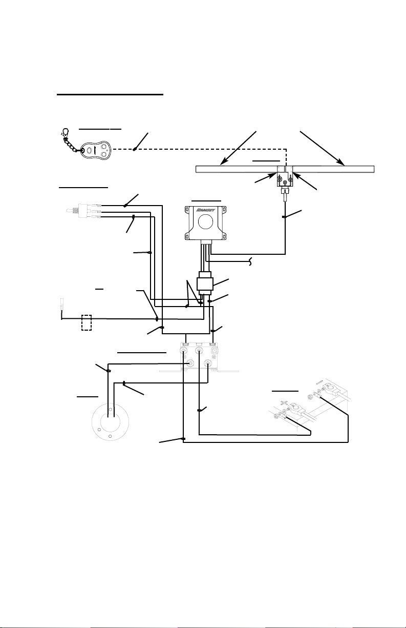
PUSH
BLACK WIRE
TO GROUND
YELLOW WIRE
SOLENOID ASS’Y.
BLACK MOTOR
LEAD
RED
BATTERY LEAD
BLACK
BATTERY LEAD
MOTOR
BATTERY
YELLOW WIRE
YELLOW
WIRE
GREEN WIRE
GREEN WIRE
RED MOTOR
LEAD
GREEN WIRE
WIRELESS
SIGNAL
RED WIRE
ANTENNA
RECEIVER
TOGGLE SWITCH
COAX CABLE
OUT
IN
RIGHT CONTACT
LEFT CONTACT
COPPER TAPE
Electrical Schematic
RED WIRE W/ WHITE
STRIPE OR
RED WIRE
TO ACCESSORY WIRE
ON VEHICLE IGNITION
MALE SPADE
CONNECTOR
ON/OFF
IN
OUT
251203 SUPERWINCH ATV 2000 & T 1500
WIRING HARNESS
TRANSMITTER
WIRE SPLICE
Page 8

251203 SUPERWINCH ATV 2000 & T 1500
6
1. Reconnect the positive power lead from
solenoid to battery.
2. Pull approximately 20 ft of cable off the
winch by hand.
3. Re-engage the winch clutch.
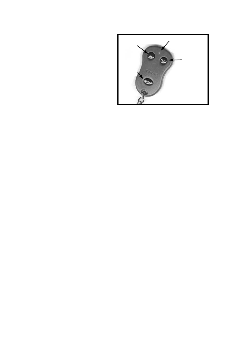
4. Test the remote transmitter. The transmitter has push buttons labeled according to their function. To turn the transmitter on, hold “ON/OFF” button down
for 2 seconds. (LED will flash, 1 flash indicates transmitter is “ON”, 2 flashes indicate transmitter is “OFF”).
5. Run winch in the “OUT” direction briefly. Make sure the motor has stopped
fully before reversing to prevent premature solenoid failure. Run winch in the
“IN” direction briefly.
6. Follow instructions in your winch owner’s manual for properly reeling in the
rest of the cable. The transmitter is clearly labeled and a red LED flashes
when the winch is in operation. To turn transmitter off, press and hold the
“ON/OFF” button for 2 seconds to disable the transmitter when winch is not
in use. This will prolong the battery life of the transmitter. The transmitter
automatically turns off after 20 minutes.
PROGRAMMING THE RECEIVER FOR USE WITH A REPLACEMENT TRANSMITTER
When you purchase a replacement transmitter, it will be necessary to reprogram
your receiver to accept the code for the new transmitter. To reprogram the
receiver, press and hold membrane located in the center of receiver face (area
marked “PUSH”). Press and hold “ON/OFF” button on transmitter for 3 seconds.
Press and hold “OUT” button for 3 seconds or until winch activates.
CAUTION: The center membrane area of the receiver face must only be pressed
when programming a new transmitter.
Testing/Operation
OUT
IN
ON/OFF
LED
Transmitter
Page 9

251204 WARN A2000 / SUPERWINCH X1, X2, X1F, X2F, EX1
* SONY CR2032 OR DURACELL DL2032
ITEM
NO.
1
2
3
4
5
6
7
8
9
10
11
12
13
14
QTY.
1
1
1
1
1
2
2
4
2
1
1
2
1
1
PART
NO.
282058
251198
251234
251190
*
416227
418140
440125
251235
440274
299724
DESCRIPTION
WIRELESS RECEIVER & TRANSMITTER KIT
DIPOLE ANTENNA KIT
SOLENOID KIT
REPLACEMENT TRANSMITTER
REPLACEMENT BATTERY
SCREW #10-24 X 3/4 TRUSS F/B
NUT #10-24 HEX LOCK
NUT #10-24 HEX Z/P
FLAT WASHER #10 Z/P
WIRE SPLICE
TOGGLE SWITCH
TUBE CLAMP
CABLE TIES
WIRE KIT
7
REMOTE RECEIVER
CABLE TIE
ANTENNA
MOUNTING
SCREWS
REMOTE
TRANSMITTER
SOLENOID
TOGGLE SWITCH
TUBE CLAMP
WIRE SPLICE
FLATWASHERS
LOCK NUTS
NUTS Z/P
WIRE KIT
Page 10

Installing the Receiver
1. Insert plastic tie through mounting ears on receiver and secure
receiver to location determined above.
2. Tighten plastic tie and clip excess.
3. Attach ground wire to ATV frame.
Caution: Do not alter the length of the ground wire as
this will affect performance of the remote.
4. Attach wiring harness to receiver & route yellow and green wires
to solenoid location.
Installing the Motor Leads
1. Remove existing manual switch, motor leads, and battery leads
from winch.
2. If you have a WARN A2000:
a. Connect black wire to #2 stud on motor.
b. Connect black with yellow stripe wire to #1 stud.
c. Route wires to solenoid location.
3. If you have a SUPERWINCH X1, X2, X1F, X2F, OR EX1:
a. Connect black wire to stud closest to front of winch.
b. Connect black with yellow stripe wire to rear stud.
c. Route wires to solenoid location.
8
251204 WARN A2000 / SUPERWINCH X1, X2, X1F, X2F, EX1
Before Beginning Installation
1. Disconnect power lead from winch to battery.
2. Disengage winch clutch.
3. Remove hood or cowling as necessary for easier access to instal-
lation area.
4. Locate & mark mounting locations for receiver, toggle switch, sole-
noid assembly, & antenna.
NOTE:
Make sure locations are close enough for wiring connections to be
made without making alterations to wire lengths. Solenoid assembly will be mounted to tube frame of ATV using supplied tube
clamps, except Polaris models which mount directly to the ATV
cross member under hood using supplied mounting screws .
Antenna will need a space of at least 15” wide under cowling or
hood for mounting in the horizontal configuration required for best
reception. Antenna is flexible and will follow the contour of the
cowling or hood. The antenna should be mounted at least 10” from
winch motor and battery leads.
Page 11

9
NOTE: For clarification see wiring schematic on page 11.
1. Attach black with yellow stripe motor lead to lower right terminal
stud “B” on solenoid.
2. Attach black motor lead to lower left terminal stud “C” on solenoid.
3. Attach connector with 2 yellow wires to the terminal directly above
the black with yellow stripe motor lead.
4. Attach connector with 2 green wires to the terminal directly above
the black motor lead.
5. Attach black battery lead to upper left terminal stud “E” on solenoid.
6. Attach red battery lead to upper right terminal stud “A” on solenoid.
Connecting Wiring to Solenoids
Installing the Solenoid
1. Mount solenoid in location determined previously.
2. Secure using (1) tube clamp, (1) #10-24 screw, (1) flat washer,
and (1) lock nut each side of solenoid assembly.
CAUTION: Be sure that no wire connections are in contact
with either the ATV frame or with each other as a direct short
will occur.
Installing the Toggle Switch
1. Route red, yellow and green wires to toggle switch location .
2. Drill 1/2” hole in location for toggle switch installation.
3. Insert switch through hole in drilled in previous step.
4. Place directional plate over switch and secure using hex nut. Make
sure directional plate is installed in the same direction as the toggle switch movement.
5. Place rubber boot over switch and tighten securely.
251204 WARN A2000 / SUPERWINCH X1, X2, X1F, X2F, EX1
Page 12

251204 WARN A2000 / SUPERWINCH X1, X2, X1F, X2F, EX1
NOTE: For clarification see wiring schematic on page 11.
1. Connect red wire to center spade.
2. Connect green wire to the toggle switch terminal in the “OUT”
position.
3. Connect the yellow wire to the toggle switch terminal in the “IN”
position.
1. Locate accessory wire on ATV ignition.
NOTE: Accessory wire should have 12 volts only when ignition key is
on.
2. Cut spade connector off and connect red wire from receiver to accessory
wire using supplied quick splice connector.
Wiring the Toggle Switch
Connecting the Power Lead
Installing the Antenna
NOTE: For clarification see wiring schematic on page 11.
1. Clean predetermined mounting surface with Isopropyl alcohol and
buff dry. (In ATVs without hoods the best place to mount the
antenna will be the underside of the ATV cowling in the highest
possible position.)
2. Remove backing from top side of double-stick tape and apply to
back side of pc board. Remove backing from other side of doublestick tape and position pc board in center on top inside surface of
cowling or hood at the predetermined mounting location.
3. Remove backing from copper tape. Carefully affix tape to terminal
on right side of pc board and follow contour of inside of cowling.
DO NOT ALTER LENGTH OF THE TAPE. Repeat for left side.
4. Route coax cable up from receiver to antenna and plug in at pc
board.
10
Page 13

E
A
C
B
11
Programing instructions: Press and hold membrane below,
press ON/OFF button on transmitter for 3 seconds ,
press OUT button for 3 seconds or until winch activation .
WWW.RAMSEY.COM
(918)438-2760 FAX(918)438-6688
Tulsa . Oklahoma, USA
.
.
PUSH
BLACK WIRE
TO GROUND
YELLOW WIRE
SOLENOID ASS’Y.
RED
BATTERY LEAD
BLACK
BATTERY LEAD
TO
MOTOR
(SEE BELOW
FOR
YOUR WINCH)
BLACK W/ YELLOW
STRIPE MOTOR
LEAD
BATTERY
YELLOW WIRE
YELLOW
WIRE
GREEN WIRE
GREEN WIRE
BLACK MOTOR
LEAD
GREEN WIRE
WIRELESS
SIGNAL
RED WIRE TO ACCESSORY
WIRE ON VEHICLE IGNITION
RED WIRE
ANTENNA
RECEIVER
TOGGLE SWITCH
COAX CABLE
OUT
IN
RIGHT CONTACT
LEFT CONTACT
COPPER TAPE
Electrical Schematic
251204 WARN A2000 / SUPERWINCH X1, X2, X1F, X2F, EX1
FRONT REAR
SUPERWINCH
X1, X2, X1F, X2F, EX1
MOTOR
BLACK
MOTOR
LEAD
BLACK W/
YELLOW STRIPE
MOTOR LEAD
#2
#1
WARN
A2000
MOTOR
BLACK
MOTOR
LEAD
BLACK W/
YELLOW STRIPE
MOTOR LEAD
WIRING HARNESS
ON/OFF
IN
OUT
TRANSMITTER
Page 14
251204 WARN A2000 / SUPERWINCH X1, X2, X1F, X2F, EX1
12
1. Reconnect the positive power lead from
solenoid to battery.
2. Pull approximately 20 ft of cable off the
winch by hand.
3. Re-engage the winch clutch.
4. Test the remote transmitter. The transmitter has push buttons labeled according to their function. To turn the transmitter on, hold “ON/OFF” button down
for 2 seconds. (LED will flash, 1 flash indicates transmitter is “ON”, 2 flashes
indicate transmitter is “OFF”).
5. Run winch in the “OUT” direction briefly. Make sure the motor has stopped
fully before reversing to prevent premature solenoid failure. Run winch in the
“IN” direction briefly.
6. Follow instructions in your winch owner’s manual for properly reeling in the
rest of the cable. The transmitter is clearly labeled and a red LED flashes
when the winch is in operation. To turn transmitter off, press and hold the
“ON/OFF” button for 2 seconds to disable the transmitter when winch is not
in use. This will prolong the battery life of the transmitter. The transmitter
automatically turns off after 20 minutes.
PROGRAMMING THE RECEIVER FOR USE WITH A REPLACEMENT TRANSMITTER
When you purchase a replacement transmitter, it will be necessary to reprogram
your receiver to accept the code for the new transmitter. To reprogram the
receiver, press and hold membrane located in the center of receiver face (area
marked “PUSH”). Press and hold “ON/OFF” button on transmitter for 3 seconds.
Press and hold “OUT” button for 3 seconds or until winch activates.
CAUTION: The center membrane area of the receiver face must only be pressed
when programming a new transmitter.
Testing/Operation
OUT
IN
ON/OFF
LED
Transmitter
Page 15

251205 WARN A2500
* SONY CR2032 OR DURACELL DL2032
ITEM
NO.
1
2
3
4
5
6
7
8
9
QTY.
1
1
1
1
1
1
1
1
1
PART
NO.
282058
251198
251190
*
440125
440274
289189
DESCRIPTION
WIRELESS RECEIVER & TRANSMITTER KIT
DIPOLE ANTENNA KIT
REPLACEMENT TRANSMITTER
REPLACEMENT BATTERY
WIRE SPLICE
CABLE TIES
WARN ADAPTER CABLE
ADAPTER CABLE STORAGE CLIP
WIRING HARNESS (NOT USED)
13
REMOTE
RECEIVER
CABLE TIE
ANTENNA
REMOTE
TRANSMITTER
WIRE SPLICE
REMOTE
ADAPTER
CABLE
WIRING
HARNESS
(NOT USED)
CABLE STORAGE CLIP
Page 16

251205 WARN A2500
Before Beginning Installation
1. Disconnect power lead from solenoid to battery.
2. Disengage winch clutch.
3. Remove hood or cowling as necessary for easier access to
installation area.
4. Locate & mark mounting locations for receiver, & antenna.
NOTE:
Make sure locations are close enough for wiring connec-
tions to be made without making alterations to wire
lengths. Antenna will need a space of at least 15” wide
under cowling or hood for mounting in the horizontal configuration required for best reception. Antenna is flexible
and will follow the contour of the cowling or hood. The
antenna should be mounted at least 10” from winch motor
and battery leads.
14
Installing the Receiver
1. Insert plastic tie through mounting ears on receiver and secure
receiver to location determined above.
2. Tighten plastic tie and clip excess.
3. Attach ground wire to ATV frame.
Caution: Do not alter the length of the ground wire
as this will affect performance of the remote.
1. Route adapter cable to receiver and plug in to receptacle.
2. Plug adapter cable into winch remote receptacle.
3. Find a suitable location for remote adapter cable storage clip.
4. Cleaning mounting surface with isopropyl alcohol and buff dry.
Affix storage clip.
NOTE: Discard remaining wiring harness.
WARNING: When winch is not in use, unplug adapter cable
and secure with adapter cable storage clip.
Installing the Adapter Cable
Page 17

251205 WARN A2500
15
Installing the Antenna
NOTE: For clarification see wiring schematic below.
1. Clean predetermined mounting surface with Isopropyl alcohol and
buff dry. (In ATVs without hoods the best place to mount the
antenna will be the underside of the ATV cowling in the highest
possible position.)
2. Remove backing from top side of double-stick tape and apply to
back side of pc board. Remove backing from other side of doublestick tape and position pc board in center on top inside surface of
cowling or hood at the predetermined mounting location.
3. Remove backing from copper tape. Carefully affix tape to terminal
on right side of pc board and follow contour of inside of cowling.
DO NOT ALTER LENGTH OF THE TAPE. Repeat for left side.
4. Route coax cable up from receiver to antenna and plug in at pc
board.
Programing instructions: Press and hold membrane below,
press ON/OFF button on transmitter for 3 seconds ,
press OUT button for 3 seconds or until winch activation .
WWW.RAMSEY.COM
(918)438-2760 FAX(918)438-6688
Tulsa . Oklahoma, USA
.
.
PUSH
BLACK WIRE
TO GROUND
TO REMOTE RECEPTACLE
REMOTE
ADAPTER CABLE
WIRELESS
SIGNAL
ANTENNA
RECEIVER
COAX CABLE
RIGHT CONTACT
LEFT CONTACT
COPPER TAPE
Electrical Schematic
ON/OFF
IN
OUT
TRANSMITTER
Page 18

251205 WARN A2500
16
1. Reconnect the positive power lead from
solenoid to battery.
2. Pull approximately 20 ft of cable off the
winch by hand.
3. Re-engage the winch clutch.
4. Test the remote transmitter. The transmitter has push buttons labeled according to their function. To operate the
winch, hold “ON/OFF” button down for 2 seconds to activate the “IN” and
“OUT” functions. (1 flash indicates transmitter is “ON”, 2 flashes indicate
transmitter is “OFF”).
5. Run winch in the “OUT” direction briefly. Make sure the motor has stopped
fully before reversing to prevent premature solenoid failure. Run winch in the
“IN” direction briefly.
6. Follow instructions in your winch owner’s manual for properly reeling in the
rest of the cable. The transmitter is clearly labeled and a red LED flashes
when the winch is in operation. To turn transmitter off, press and hold the
“ON/OFF” button for 2 seconds to disable the transmitter when winch is not
in use. This will pro-long the battery life of the transmitter. The transmitter
automatically turns off after 20 minutes.
WARNING: Unplug remote adapter cable when not in use.
PROGRAMMING THE RECEIVER FOR USE WITH A REPLACEMENT TRANSMITTER
When you purchase a replacement transmitter, it will be necessary to reprogram
your receiver to accept the code for the new transmitter. To reprogram the
receiver, press and hold membrane located in the center of receiver face (area
marked “push”). Press and hold “ON/OFF” button on transmitter for 3 seconds.
Press and hold “OUT” button for 3 seconds or until winch activates.
CAUTION: The center membrane area of the receiver face must only be pressed
when programming a new transmitter.
T
esting/Operation
OUT
IN
ON/OFF
LED
Transmitter
Page 19

251206 SUPERWINCH X1, X2, X1F, X2F, EX1 (WITH HAND HELD REMOTE)
17
* SONY CR2032 OR DURACELL DL2032
ITEM
NO.
1
2
3
4
5
6
7
8
9
QTY.
1
1
1
1
1
1
1
1
1
PART
NO.
282058
251198
251190
*
440125
440274
289190
DESCRIPTION
WIRELESS RECEIVER & TRANSMITTER KIT
DIPOLE ANTENNA KIT
REPLACEMENT TRANSMITTER
REPLACEMENT BATTERY
WIRE SPLICE
CABLE TIES
SUPERWINCH ADAPTER CABLE
CABLE STORAGE CLIP
WIRING HARNESS (NOT USED)
REMOTE
RECEIVER
CABLE TIE
ANTENNA
REMOTE
TRANSMITTER
WIRE SPLICE
REMOTE
ADAPTER
CABLE
CABLE STORAGE CLIP
WIRING
HARNESS
(NOT USED)
Page 20

251206 SUPERWINCH X1, X2, X1F, XF2 EX1 (W/ HAND HELD REMOTE)
Before Beginning Installation
1. Disconnect power lead from solenoid to battery.
2. Disengage winch clutch.
3. Remove hood or cowling as necessary for easier access to installation area.
4. Locate & mark mounting locations for receiver, & antenna.
NOTE:
Make sure locations are close enough for wiring connec-
tions to be made without making alterations to wire
lengths. Antenna will need a space of at least 15” wide
under cowling or hood for mounting in the horizontal configuration required for best reception. Antenna is flexible
and will follow the contour of the cowling or hood. The
antenna should be mounted at least 10” from winch motor
and battery leads.
Installing the Receiver
1. Insert plastic tie through mounting ears on receiver and secure
receiver to location determined above.
2. Tighten plastic tie and clip excess.
3. Attach ground wire to ATV frame.
Caution: Do not alter the length of the ground wire as this
will affect performance of the remote.
18
1. Route adapter cable to receiver and plug in to receptacle.
2. Plug adapter cable into winch remote receptacle.
3 Find a suitable location for remote adapter cable storage clip.
4. Clean mounting surface with isopropyl alcohol and buff dry. Affix
storage clip.
NOTE: Discard remaining wiring harness.
WARNING: When winch is not in use, unplug adapter cable and
secure with adapter cable storage clip.
Installing the Adapter Cable
Page 21

251206 SUPERWINCH X1, X2, X1F, XF2 EX1
(W/ HAND HELD REMOTE)
19
Installing the Antenna
NOTE: For clarification see wiring schematic below.
1. Clean predetermined mounting surface with Isopropyl alcohol and
buff dry. (In ATVs without hoods the best place to mount the
antenna will be the underside of the ATV cowling in the highest
possible position.)
2. Remove backing from top side of double-stick tape and apply to
back side of pc board. Remove backing from other side of doublestick tape and position pc board in center on top inside surface of
cowling or hood at the predetermined mounting location.
3. Remove backing from copper tape. Carefully affix tape to terminal
on right side of pc board and follow contour of inside of cowling.
DO NOT ALTER LENGTH OF THE TAPE. Repeat for left side.
4. Route coax cable up from receiver to antenna and plug in at pc
board.
Programing instructions: Press and hold membrane below,
press ON/OFF button on transmitter for 3 seconds ,
press OUT button for 3 seconds or until winch activation .
WWW.RAMSEY.COM
(918)438-2760 FAX(918)438-6688
Tulsa . Oklahoma, USA
.
.
PUSH
BLACK WIRE
TO GROUND
TO REMOTE RECEPTACLE
REMOTE
ADAPTER CABLE
WIRELESS
SIGNAL
ANTENNA
RECEIVER
COAX CABLE
RIGHT CONTACT
LEFT CONTACT
COPPER TAPE
Electrical Schematic
ON/OFF
IN
OUT
TRANSMIT
TER
Page 22

251206 SUPERWINCH X1, X2, X1F, X2F, EX1(WITH HAND HELD REMOTE)
20
1. Reconnect the positive power lead from
solenoid to battery.
2. Pull approximately 20 ft of cable off the
winch by hand.
3. Re-engage the winch clutch.
4. Test the remote transmitter. The transmitter has push buttons labeled according to their function. To turn the transmitter on, hold “ON/OFF” button down
for 2 seconds. (LED will flash, 1 flash indicates transmitter is “ON”, 2 flashes
indicate transmitter is “OFF”).
5. Run winch in the “OUT” direction briefly. Make sure the motor has stopped
fully before reversing to prevent premature solenoid failure. Run winch in the
“IN” direction briefly.
6. Follow instructions in your winch owner’s manual for properly reeling in the
rest of the cable. The transmitter is clearly labeled and a red LED flashes
when the winch is in operation. To turn transmitter off, press and hold the
“ON/OFF” button for 2 seconds to disable the transmitter when winch is not
in use. This will prolong the battery life of the transmitter. The transmitter
automatically turns off after 20 minutes.
WARNING: Unplug remote adapter cable when not in use.
PROGRAMMING THE RECEIVER FOR USE WITH A REPLACEMENT TRANSMITTER
When you purchase a replacement transmitter, it will be necessary to reprogram
your receiver to accept the code for the new transmitter. To reprogram the
receiver, press and hold membrane located in the center of receiver face (area
marked “PUSH”). Press and hold “ON/OFF” button on transmitter for 3 seconds.
Press and hold “OUT” button for 3 seconds or until winch activates.
CAUTION: The center membrane area of the receiver face must only be pressed
when programming a new transmitter.
Testing/Operation
OUT
IN
ON/OFF
LED
Transmitter
Page 23

Trouble Shooting Guide
Correction
Turn transmitter on (See
Testing/Operation) .
Replace Battery.
In extremely cold temperatures, keep transmitter in a
pocket of innermost layer of
clothing when not in use.
Make sure receiver ground
wire has good connection to
ATV ground.
Program receiver (refer to
Programming the Receiver).
Mount antenna at least 10
inches from winch motor
and battery leads.
Move around the ATV until
normal operation resumes .
Keep transmitter in direct line
of sight with antenna for optimal operation.
Stay within 50 ft. of antenna
for optimal operation.
Make sure no similar devices
are within 50 ft. of vehicle.
Make sure ATV battery
voltage is above 9.5 volts.
Possible Cause
Transmitter is off.
Low transmitter battery voltage.
Transmitter temperature
below 0°F (-18°C).
Bad ground connection.
Receiver not coded with
transmitter.
Antenna mounted too
close to winch motor and
battery leads.
External environmental conditions causing intermittent
operation in a specific
transmitter location.
Signal deflecting off of land
mass or solid structures.
Transmitter out of operating
range.
Operating within 50 ft. of
any similar device.
Low ATV battery voltage.
Condition
Transmitter won’t operate
Remote receiver will not
operate.
Intermittent operation.
21
Page 24

RAMSEY WINCH COMPANY
P.O. BOX 581510 TULSA, OKLAHOMA 74158-1510 USA PHONE: (918) 438-2760 FAX: (918) 438-6888 http://www.ramsey.com
OM-914059-0106-J
Warranty Information
If the need should arise, warranty procedure is outlined on the back of your self-addressed, postage paid warranty
card. Please read and fill out the enclosed warranty card and send it to Ramsey Winch Company. If you have any
problems with your wireless remote, please follow instructions for prompt service on all warranty claims.
Limited Lifetime Warranty
Ramsey Winch offers a limited lifetime warranty for each new Ramsey wireless remote against manufacturing defects in workmanship and materials on all
manufactured components.
The wireless remote carries a limited 1-year warranty.
The obligation under this warranty, statutory or otherwise, is limited to the replacement or repair at the manufacturers factory, or at a point designated by the
manufacturer, of such part as shall appear to the manufacturer, upon inspection of such part, to have been defective in material or workmanship. This
Warranty does not obligate Ramsey Winch Company to bear the cost of transportation charges in connection with the replacement or repair of defective
parts, nor shall it apply to a product upon which repairs or alterations have been made, unless authorized by the manufacturer, or for equipment misused,
neglected, or improperly installed.
Impor
tant notice: To the fullest extent permitted by applicable law, the following are hereby excluded and disclaimed: 1. All warranties of fitness for a particular purpose; 2. All warranties of merchantability; 3. All claims for consequential or incidental damages. There are no warranties that extend beyond the description that appears on the face hereof.
Some states do not allow the above exclusions or disclaimers in consumer transactions and as such this disclaimer/exclusion may not apply
to your particular case.
To the extent such warranties of fitness for a particular purpose or merchantability are deemed to apply to this product, they exist only for so
long as the express limited warranty elsewhere set forth is in existence.
Ramsey Winch Company makes no warranty in respect to accessories, same being subject to the warranties of their respective manufacturers.
Ramsey Winch Company, whose policy is one of continuous product improvement, reserves the right to improve any product through changes in design or
materials as it may deem desirable without being obligated to incorporate such changes in products of previous manufacture.
If field service at the request of the buyer is rendered and the fault is found not to be with Ramsey Winch Company’s product, the buyer shall pay the time
and expense of the field representative. Bills for service, labor or other expenses which have been incurred by the buyer without express approval or authorization by Ramsey Winch Company will not be accepted.
This Warranty gives you specific legal rights and you may also have other legal rights which vary from state to state.
 Loading...