

Page 1
Ramsey Winch Company
OWNER'S MANUAL
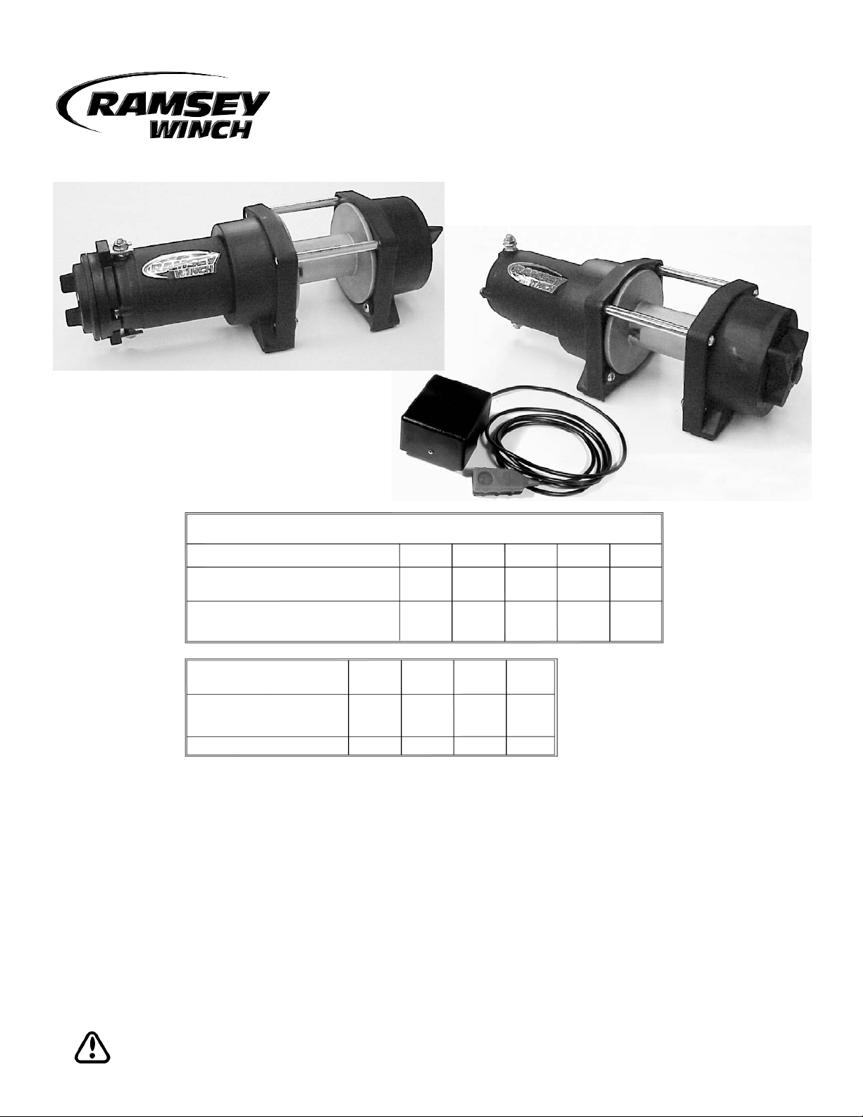
ATV Electric Winch Model ATV1800T
Congratulations
You have purchased the finest winch available in its service class. It features a highly efficient 3 stage planetary
gear set which transmits torque from a permanent magnet motor. A safe positive clutch allows free spooling for
quick cable deployment. Your Ramsey winch was
designed and manufactured to provide you with the
utmost in utility. As with any device that combines power
and movement in its use, there are dangers if improperly
used.
At the same time, there are easier and faster ways for
getting the job done if certain precautions are taken first.
Please read this manual carefully. It contains useful ideas
in obtaining the most efficient operation from your
Ramsey Winch and safety procedures you need to know
before beginning use. When you follow our guidelines for
operation, your Ramsey winch will give you many years
of satisfying service. Thank you for choosing Ramsey.
You will be glad you have one working for you.
Intended Purpose for Ramsey ATV 1800T Series
Winch: Self recovery of vehicles, pulling of loads.
CAUTION: Read and understand this manual before installation and operation of winch. See Safety Precautions.
* CABLE MUST BE UNIFORMLY WOUND ONTO DRUM.
815
1,800
1
2.12
7
ATV1800T WINCH
LAYER OF CABLE
3.7
101
544
1,200
72
31
4.2
272
600
19.1
5.8
LOAD
NO
12.2
13.8
135
9.2
2.8
816
1,800
11.3
37
498
1,100
4.56
15
680
1,500
7.6
25
544
1,200
2
3
15.2
50
453
1,000
4
5
(lbs)
(kgs)
Rated line pull per layer
Cumulative cable
capacity per layer
(ft)*
(m)*
Line pull
(lbs)
(kgs)
Line speed
(fpm)
(mpm)
Amp draw
(12v)
first layer
first layer
(5 mm dia. cable)
Noise Level: 81 dB(A)
Page 2
Safety Precautions To Guard Against
Possible Injury.....
A. Keep yourself and others a safe distance to the side
of the cable when pulling under load.
B. Do not step over a cable, or near a cable under load.
C. Use supplied hook strap when handling hook for
spooling wire rope.
D. Do not use ATV to pull a load on the winch cable.
This could result in cable breakage and/or winch
damage
E. Use a heavy rag or gloves to protect hands from
burrs when handling winch cable.
F. Apply blocks to wheels when ATV is on an incline.
G. Winch clutch should be disengaged when winch is
not in use and fully engaged when in use.
H. Modification, alteration, or deviation to the winch
should only be made by Ramsey Winch Company.
I. Keep the duration of your pulls as short as possible.
If the motor becomes uncomfortably hot to the
touch, stop and let it cool for a few minutes. Do not
pull more than one minute at or near the rated load.
Do not maintain power to the winch if the motor
stalls. Electric winches are for intermittent usage
and should not be used in constant duty applications.
J. Disconnect the remote control switch from the
winch when not in use. A safety ON-OFF switch
on your ATV is required.
K. Do not use winch in hoisting applications due to
required hoist safety factors and features.
L. To respool correctly, it is necessary to keep a slight
load on the cable. Do not allow the cable to slip
through your hand and do not approach the winch
too closely. When all the cable except a few feet is in,
stop and finish spooling in cable by rotating the drum
by hand with clutch disengaged. Always use hook
strap to hold hook when spooling.
Tips for Safe Operation
Don't underestimate the potential danger in winching
operations. Neither should you fear them. Do learn the
basic dangers and avoid them.
Observe spooling of cable onto drum. Side pulls can
cause cable to pileup at one end of the drum. To correct
uneven stacking, spool out that section of the cable and
move it to the other end of the drum and continue winching. Uneven spooling which causes cable pileup can
interfere with the winch tie rods causing damage to the
winch.
Never connect the hook back to the cable. This causes
cable damage. Always use a sling or chain of suitable
strength.
Observe your winch while winching. If possible, while
standing at a safe distance. If you use ATV drive to
assist, stop and get off every few feet to assure the
cable is not piling up in one corner. Jamming cable can
break your winch.
Contents
Performance Specifications . . . . . . . . . . . . . . . .cover
Safety Precautions . . . . . . . . . . . . . . . . . . . . . . . . . .2
Tips for Safe Operation . . . . . . . . . . . . . . . . . . . . . .2
Techniques of Operation . . . . . . . . . . . . . . . . . . . . . .3
General Installation . . . . . . . . . . . . . . . . . . . . . . . . . .3
Winch Operation . . . . . . . . . . . . . . . . . . . . . . . . . . .4
Maintenance . . . . . . . . . . . . . . . . . . . . . . . . . . . . . .4
Cable Installation . . . . . . . . . . . . . . . . . . . . . . . . . . .4
Manual Control Switch Operation . . . . . . . . . . . . . . .4
Electrical Connections and Operations . . . . . . . . . . .5
Electrical Schematics . . . . . . . . . . . . . . . . . . . . . . . .6
Winch Mounting . . . . . . . . . . . . . . . . . . . . . . . . . . . .7
Solenoid Mounting . . . . . . . . . . . . . . . . . . . . . . . . . .7
Trouble Shooting Guide . . . . . . . . . . . . . . . . . . . . . .8
Winch Parts List (Manual Switch) . . . . . . . . . . . . . .9
Winch Parts List (Remote Switch) . . . . . . . . . . . . .10
Warranty . . . . . . . . . . . . . . . . . . . . . . . . .back cover
2
Page 3
Do not attach tow hooks to winch mounting apparatus.
They must attach to ATV frame.
When double lining during stationary winching, the winch
hook should be attached to the chassis of the ATV. Since
the greatest pulling power is achieved on the innermost
layer of your winch, it is desirable to pull off as much
line as you can for heavy pulls. If this is not practical,
use a snatch block and double line arrangement.
Neat, tight spooling avoids cable binding which is
caused when a load is applied and the cable is pinched
between two other wraps of cable. If this happens, alternately power the winch in and out a few inches. Do not
attempt to work a bound cable under load, free by hand.
Techniques of Operation
The best way to get acquainted with how your winch
operates is to make a few test runs before you actually
need to use it. Plan your test in advance. Remember
you hear your winch as well as see it operate. Get to
recognize the sound of a light steady pull, a heavy pull,
and sounds caused by load jerking or shifting. Soon you
will gain confidence in operating your winch and its use
will become second nature with you.
Your winch will not only pull your ATV up or ease your
ATV down a steep grade, it will also pull another ATV or a
load while your ATV is anchored in a stationary position.
When pulling a heavy load, place a blanket, jacket or tarpaulin over the cable five or six feet from the hook. It
will slow the snap back in the event of a broken cable.
Use the ATV wheel power to help the winch, but don't
overtake the winch line. Plan your pull. You can't
always hook up and pull out in one step. Examine all the
areas for anchoring possibilities as well as leverage situations, direction, and goal.
General Installation
The winch shown in this owner’s manual is solely and
exclusively designed for ATV mounted, non-industrial
applications. All other applications will void warranty.
1. Install Winch and Mounting Kit according to instructions supplied with Mounting Kit. Tighten mounting
bolts to 16 ft-lbs (21.6 Nm) torque.
2. Do not attach motor and battery leads until instructed
to do so.
3. It is very important that the winch be mounted
on a flat surface, with the cable underwound as
shown in the dimensional drawing on page 7.
CAUTION: Supplied 7/8” long mounting bolts
with lockwashers are for a recommended
winch mounting plate thickness of 3/16”. If
a different mounting plate thickness is used,
the bolt length must be adjusted accordingly
or damage to winch may occur. Replacement
bolts must be SAE Grade 5 or equivalent.
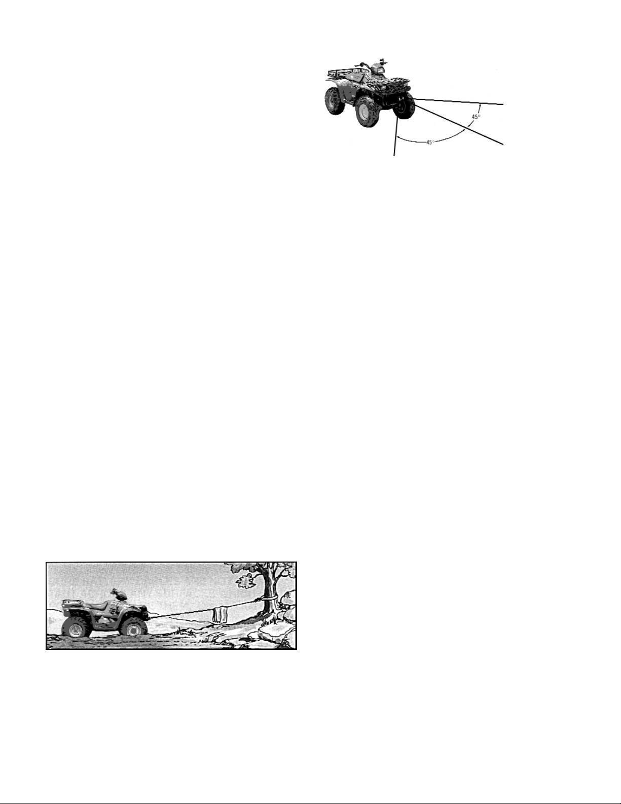
Winches equipped with cable guide fairleads can pull from
several directions. Pull from an angle only to straighten up
the ATV--otherwise you can damage structural members or
other parts of your ATV and cause excess cable buildup on
one end of the winch drum.
For basic self-recovery, anchor to a tree or heavy rock. When
anchoring to a tree, always use a tree trunk protector.
3
Page 4
Winch Operation
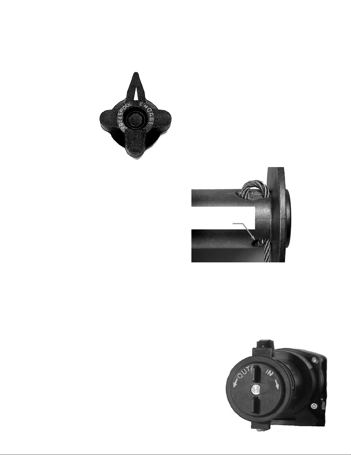
The winch clutch allows rapid unspooling of the wire
rope for hooking onto the load or anchor point. The
clutch is operated by the shifter located on the end of the
winch as follows:
1. To disengage the clutch,
turn the clutch shifter to
the "FREESPOOL" position. When the clutch is
in FREESPOOL, the arrow
on the clutch knob will
point to FREESPOOL on
the decal on the winch.
Wire rope may now be
freespooled off the drum.
2. To engage the clutch,
turn the clutch shifter to the "ENGAGED" position.
When the clutch is in ENGAGED position, the arrow
on the clutch knob will point to ENGAGED on the
decal on the winch. The winch is now ready for
pulling.
Your battery must be kept in good condition. A fully
charged battery and proper connections are essential.
Run the vehicle engine during winching operations to
keep battery charged.
Maintenance
Corrosion on electrical connections will reduce performance or may cause a short. Clean all connections. In
salty environments use a silicone sealer to protect from
corrosion.
All moving parts in the winch are permanently lubricated
with broad temperature range lithium based grease.
Lubricate cable periodically using light penetrating oil.
Inspect for broken strands and replace if necessary. If
the cable becomes worn or damaged, it must be
replaced.
Cable Installation
Note: Cable should be installed so that it feeds
from the bottom of the drum.
Unwind the new cable by rolling it out along the ground
to prevent kinking. Remove old cable and observe the
manner in which it is attached to the cable drum flange,
watching carefully for the cable anchor puck.
Before installing the new cable assembly, securely wrap
the end of the cable with tape to prevent fraying.
Slide the cable through narrow end of the pocket against
drum flange and wrap the cable around the anchor puck.
Pull the cable and anchor back into the wide end of the
pocket leaving approximately 1/8” beyond edge of pocket as shown. Use a hammer and drift punch to drive the
back side of the wire rope, firmly seating the wire rope
and anchor into the pocket.
Wind on the cable by pulling in a light load to keep the
tension constant. Allow the cable to swivel by using a
length of chain or a swivel block between the cable hook
and the load.
Manual Control Switch Operation
The manual control switch assembly is attached to the
motor power terminals. Rotation of the switch clockwise
spools cable “in” and counterclockwise spools cable
“out”.
The short end of the cable should
extend approximately 1/8” beyond
the top edge of pocket.
4
Page 5

Electrical Connections and Operations
For normal self-recovery work, your existing electrical
system is adequate. Your battery should be kept in good
condition. A fully charged battery and proper connections are essential. Run the ATV engine during winching
operations to keep battery charged.
Remote Switch
The solenoid assembly reverses the direction of cable
drum rotation. Route red and black battery cables up to
battery. CAUTION: BE SURE BATTERY CABLES ARE
NOT DRAWN TAUT ACROSS ANY SURFACES WHICH
COULD POSSIBLY DAMAGE THEM.
1. As shown on the schematic on the next page, con-
nect the red battery lead to the positive (+) terminal
of the ATV battery.
2. Connect the black battery lead to the negative (-) ter-
minal of the ATV battery.
3. Connect the black motor lead to the #2 pole of the
motor.
4. Connect the black with yellow stripe motor lead to
the #1 pole of the motor.
5. The remote switch plugs into the receptacle on the
solenoid.
An emergency stop switch (reference Ramsey part no.
282053) is required between the positive (+) battery ter-
minal and the red battery lead. An overload device is
required to prevent winch from exceeding the rated line
pull.
The remote control switch is waterproof. It has push button stations on either side. It is designed this way to prevent quick winch reversals which can lead to solenoid
failure. Make sure the motor has stopped fully before
reversing. To actuate winch, simply plug remote control
switch into the receptacle in the solenoid cover. Run
winch forward and reverse to check connection and
determine winch operating directions. Snap appropriate
“IN” and “OUT” disc into proper thumb cavity. The
switch is also color coded to aid you in not having to
guess which direction your winch will run in. DO NOT
LEAVE SWITCH PLUGGED IN WHEN WINCH IS NOT IN
USE.
Manual Switch
As shown on the schematic on the next page, the only
connections that need to be made on the manual switch
are to connect the red battery lead to the positive (+)
battery terminal and the black battery lead to the negative
(-) battery terminal. The winch will operate in the direction marked on the switch unless the battery leads are
reversed.
There is no need to disconnect the manual switch when
not in use.
5
Page 6

Manual Switch
RED
BATTERY LEAD
BLACK
BATTERY LEAD
BA
TTERY
MANU
AL
CONTROL
SWITCH
BLACK W/ YELLOW
STRIPE MOTOR LEAD
RED
BATTERY LEAD
BLACK
BATTERY LEAD
BATTERY
BLACK MOTOR
LEAD
#1
MOTOR
#2
ELECTRICAL SCHEMATICS
Remote Switch
6
SOLENOID
Page 7

Winch Mounting
Solenoid Mounting (Remote Switch)
*Mounting Hole Pattern
Four 11/32” (8,6 mm) diameter
holes on 4.88” (124 mm) x 3.00”
(76,2 mm) pattern
5/16-18 NC
4 Places
7
*Mounting Hole P
attern
Three 9/32” (7,1 mm) diameter
holes on 4.75” (120,7 mm) x
4.13” (104,9 mm) pattern
Note: Allow sufficient clearance
next to receptacle to plug remote
switch into.
Cable must exit
under the drum
Page 8

CONDITION POSSIBLE CAUSE CORRECTION
Defective solenoid or stuck
solenoid (Remote switch only).
Jar solenoid assembly to free contacts. Check each solenoid
by applying +12 volts to coil-terminal (it should make an
audible click when energized).
Defective remote switch plug
(Remote switch only)
Disengage winch clutch, remove remote control switch from
the socket and jump pins at 8 and 4 o'clock. Motor should
run. Jump pins at 8 and 10 o'clock. Motor should run.
Defective manual switch. Replace manual switch.
MOTOR RUNS
EXTREMELY HOT
Long period of operation Cooling-off periods are essential to prevent overheating.
Insufficient battery. Test for faulty vehicle battery
Bad connection Check battery cable for corrosion; clean and grease.
Insufficient charging system Replace with larger capacity charging system.
MOTOR RUNS, BUT DRUM
DOES NOT TURN
Clutch not engaged
If clutch engaged but symptoms still exist, it will be
necessary to disassemble winch to determine cause and
repair.
Defective solenoid or stuck
solenoid (Remote switch only).
Jar solenoid assembly to free contacts. Check each solenoid
by applying +12 volts to coil-terminal (it should make an
audible click when energized).
Defective remote switch plug
(Remote switch only)
Disengage winch clutch, remove remote control switch from
the socket and jump pins at 8 and 4 o'clock. Motor should
run. Jump pins at 8 and 10 o'clock. Motor should run.
Defective manual switch. Replace manual switch.
Defective motor.
If solenoids operate, check for voltage at armature post;
replace motor.
Loose connections
Check all electrical connections from the battery to the
motor.
MOTOR WATER
DAMAGED
Submerged in water or water from
high pressure car wash.
Allow to drain and dry thoroughly, then run motor without
load in short bursts to dry windings.
WINCH RUNS IN
OPPOSITE DIRECTION
Battery leads crossed (Manual
switch only)
Reverse red and black battery leads.
MOTOR RUNS IN ONLY
ONE DIRECTION
MOTOR RUNS, BUT WITH
INSUFFICIENT POWER OR
WITH LOW LINE SPEED
MOTOR WILL NOT
OPERATE
TROUBLESHOOTING
8
Page 9

1
2
6
4
3
7
8
10
11
12
13
ATV 1800 T PARTS (MANUAL SWITCH)
ATV 1800 T PARTS LIST (MANUAL SWITCH)
ITEM NO. QTY. PART NO. DESCRIPTION
1 1 251191 CLUTCH KIT
2 1 251192 CABLE DRUM KIT
3 1 251195 BUSHING KIT
4 1 251196 TIE BAR KIT
5 1 251247 MOTOR END GEAR SET
6 1 251213 CLUTCH END GEAR KIT
7 1 251214 MOTOR KIT
8 1 251238 MANUAL CONTROL SWITCH
9 1 256116 BRAKE KIT
10 1 289197 BATTERY WIRE (BLACK)
11 1 289199 BATTERY WIRE (RED)
12 1 335044 BOOT
13 1 251075 HAWSE FAIRLEAD KIT
9
5
9
Page 10

2
5
3
4
6
7
ATV 1800 T PARTS (REMOTE SWITCH)
ATV 1800 T PARTS LIST (REMOTE SWITCH)
ITEM NO. QTY. PART NO. DESCRIPTION
1 1 251110 REMOTE SWITCH ASSY
2 1 251191 CLUTCH KIT
3 1 251192 CABLE DRUM KIT
4 1 251195 BUSHING KIT
5 1 251196 TIE BAR KIT
6 1 251213 CLUTCH END GEAR KIT
7 1 251214 MOTOR KIT
8 1 251234 SOLENOID KIT
9 1 251247 MOTOR END GEAR SET
10 1 251248 SOLENOID MOUNTING KIT
11 1 256116 BRAKE KIT
12 1 289197 72" BLACK BATTERY LEAD
13 1 289199 72" RED BATTERY LEAD
14 1 289203 48" BLACK MOTOR LEAD
15 1 289204 48" BLACK W/ YELLOW STRIPE MOTOR LEAD
16 1 251075 HAWSE FAIRLEAD KIT
12
13
14
15
10
8
10
16
1
9
11
Page 11

NOTES
Page 12

RAMSEY WINCH COMPANY
P.O. BOX 581510 TULSA, OKLAHOMA 74158-1510 USA PHONE: (918) 438-2760 FAX: (918) 438-6888
http://www.ramsey.com
OM-914094-0904-D
Warranty Information
Ramsey Winches are designed and built to exacting specifications. Care and skill go into every winch we make. If the need should arise,
warranty procedure is outlined on the back of your self-addressed, postage paid warranty card. Please read and fill out the enclosed warranty card and send it to Ramsey Winch Company. If you have any problems with your winch, please follow instructions for prompt service
on all warranty claims.
Limited Lifetime Warranty
Ramsey Winch offers a limited lifetime warranty for each new Ramsey ATV winch against manufacturing defects in workmanship and materials on all manufactured components.
Warranty registration cards for each winch must be submitted at the time of purchase, or within 90 days. Online registration of your winch is
available at www.ramsey.com.
New cable assemblies are warranted against defects in workmanship and materials. No warranty applies after initial use.
All Ramsey mounting kits and other accessories carry a 1- year limited warranty against defects in materials and workmanship.
This warranty is void if winch is used in commercial/industrial applications other than front mount self recovery.
Electrical components consisting of motors, solenoids, wiring, wire connectors, and associated parts carry a limited 1-year warranty.
The obligation under this warranty, statutory or otherwise, is limited to the replacement or repair at the manufacturers factory, or at a point designated by the manufacturer, of such part as shall appear to the manufacturer, upon inspection of such part, to have been defective in material or workmanship. This Warranty does not obligate Ramsey Winch Company to bear the cost of transportation charges in connection with the
replacement or repair of defective parts, nor shall it apply to a product upon which repairs or alterations have been made, unless authorized
by the manufacturer, or for equipment misused, neglected, or improperly installed.
Important notice: To the fullest extent permitted by applicable law, the following are hereby excluded and disclaimed:
1. All warranties of fitness for a particular purpose;
2. All warranties of merchantability;
3. All claims for consequential or incidental damages.
There are no warranties that extend beyond the description that appears on the face hereof.
Some states do not allow the above exclusions or disclaimers in consumer transactions and as such this disclaimer/exclusion may
not apply to your particular case.
To the extent such warranties of fitness for a particular purpose or merchantability are deemed to apply to this product, they exist
only for so long as the express limited warranty elsewhere set forth is in existence.
Ramsey Winch Company makes no warranty in respect to accessories, same being subject to the warranties of their respective manufacturers.
Ramsey Winch Company, whose policy is one of continuous product improvement, reserves the right to improve any product through changes
in design or materials as it may deem desirablewithout being obligated to incorporate such changes in products of previous manufacture.
If field service at the request of the buyer is rendered and the fault is found not to be with Ramsey Winch Company’s product, the buyer shall
pay the time and expense of the field representative. Bills for service, labor or other expenses which have been incurred by the buyer without
express approval or authorization by Ramsey Winch Company will not be accepted.
This Warranty gives you specific legal rights and you may also have other legal rights which vary from state to state.
 Loading...