

Page 1
OPERATING, SERVICE AND
MAINTENANCE MANUAL
WILDCAT SERIES 80,000 LB
INDUSTRIAL
CAUTION: READ AND UNDERSTAND THIS MANUAL BEFORE INSTALLATION AND OPERATION OF
WINCH. SEE WARNINGS!
WINCH
Page 2

TABLE OF CONTENTS
WARRANTY INFORMATION ............................................................................................................... 1
SPECIFICATIONS ................................................................................................................................ 1
WARNINGS .......................................................................................................................................... 1
HYDRAULIC SYSTEM REQUIREMENTS ........................................................................................... 2
CABLE INSTALLATION ...................................................................................................................... 3
CLUTCH OPERATION ......................................................................................................................... 4
WINCH OPERATION ........................................................................................................................... 4
MAINTENANCE ................................................................................................................................... 4
LUBRICATION TABLE ........................................................................................................................ 5
TROUBLE SHOOTING GUIDE ............................................................................................................ 5
INSTRUCTIONS FOR DISASSEMBLY ................................................................................................ 6
DISASSEMBLY OF CARRIER ASSEMBLY ...................................................................................... 14
ASSEMBLY OF CARRIER ASSEMBLY ............................................................................................ 15
CARRIER ASSEMBLIES ................................................................................................................... 16
HOSE HOOKUP ................................................................................................................................. 17
PARTS DRAWING ............................................................................................................................. 18
PARTS LIST ....................................................................................................................................... 19
AIR CYLINDER .................................................................................................................................. 20
DIMENSIONAL DRAWING ................................................................................................................ 21
LIMITED WARRANTY ........................................................................................................................ 22
Page 3

Lb
30 9
36 11
42 13
48 15
54 16
RAMSEY HYDRAULIC PLANETARY WINCH MODEL WILDCAT 80K
PLEASE READ THIS MANUAL CAREFULLY
This manual contains useful ideas in obtaining the most efficient operation from your Ramsey Winch, and safety
procedures one needs to know before operating a Ramsey Winch. Do not operate this winch until you have carefully
read and understand the "WARNINGS" and "OPERATION" sections of this manual.
WARRANTY INFORMATION
Ramsey Winches are designed and built to exacting specifications. Great care and skill go into every winch we make.
If the need should arise, warranty procedure is outlined on the back of your self-addressed postage paid warranty card.
Please read and fill out the enclosed warranty card and send it to Ramsey Winch Company. If you have any problems
with your winch, please follow instructions for prompt service on all warranty claims. Refer to back page for limited
warranty.
SPECIFICATIONS*
APPROXIMATE WEIGHT: 1700 LBS
WORKING PRESSURE: 2500 PSI
CABLE DIAMETER: 1 INCH
MAX FLOW: 60 GPM
LAYER
OF
CABLE
1 50 20 80000 36280
2 115 45 66600 30200
3 185 73 57100 25900
4 270 106 50000 22670
5 365 144 44400 20130
* These specifications are based on recommended wire rope of 1” Extra Improved Plow Steel Cable and a 9.0
cu. in. / Rev. motor.
NOTE: The rated line pulls shown are for the winch only. Consult the wire rope manufacturer for wire rope ratings.
CABLE
CAPACITY
Ft m Lb Kg
LINE PULL
LOW SPEED
LINE SPEED
fpm mpm
HIGH SPEED
LINE PULL LINE SPEED
Kg fpm mpm
30000
25000
21400
18700
16600
13630 60 18
11350 72 22
9730 84 26
8520 96 29
7560 108 33
WARNINGS:
CLUTCH MUST BE FULLY ENGAGED BEFORE STARTING THE WINCHING OPERATION.
DO NOT START WINCH MOTOR BEFORE ENGAGING CLUTCH.
DO NOT DISENGAGE CLUTCH UNDER LOAD.
STAY OUT FROM UNDER AND AWAY FROM RAISED LOADS.
STAND CLEAR OF CABLE WHILE PULLING. DO NOT TRY TO GUIDE CABLE.
DO NOT EXCEED MAXIMUM LINE PULL RATINGS SHOWN IN TABLE.
DO NOT USE WINCH TO LIFT, SUPPORT, OR OTHERWISE TRANSPORT PEOPLE.
A MINIMUM OF 5 WRAPS OF CABLE AROUND THE DRUM BARREL IS NECESSARY TO HOLD THE LOAD.
CABLE ANCHOR IS NOT DESIGNED TO HOLD LOAD.
BAND BRAKE IS NOT TO BE USED TO HOLD LOAD
1 OM-914207-0211-D
Page 4
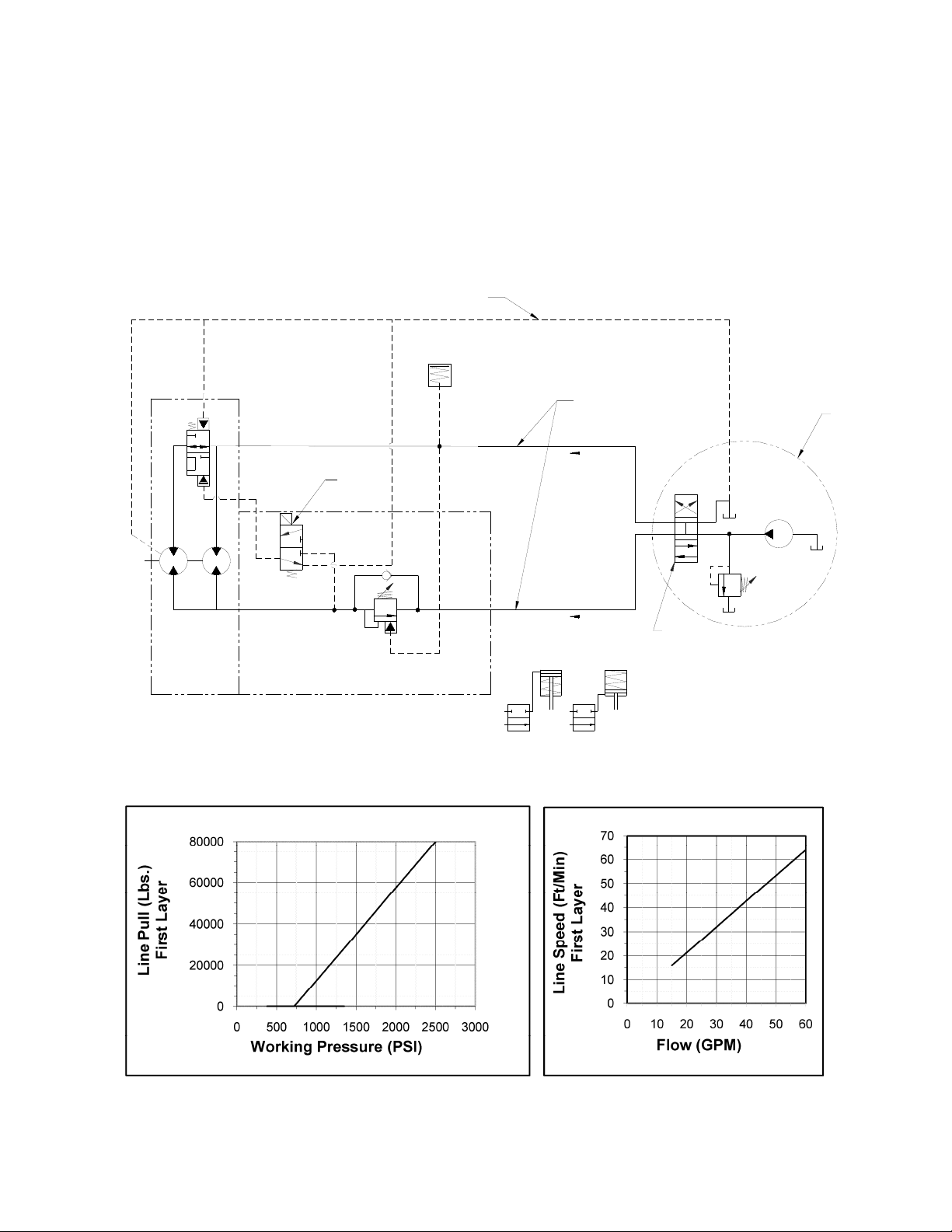
HYDRAULIC SYSTEM REQUIREMENTS
Refer to the performance charts, below, to properly match your hydraulic system to winch performance.
The charts consist of:
(1) Line pull (lb.) first layer vs. working pressure (PSI) and (2) line speed, first layer (FPM) vs. gallons per
minute (GPM). Performance based on a motor displacement of 9.0 cubic inches/rev with 60 GPM
maximum flow rate. Motor has (2) 1”-12 SAE straight thread o-ring ports.
Note: A motor spool (open center) directional control valve is required for brake operation.
LOW PRESSURE LINE
DIRECT LINE TO TANK
BRAKE
MOTOR CASE DRAIN
MOTOR 2 SPEED
PERFORMANCE CHARTS
SAE -16
1" TUBING SIZE
12 VDC
PORT #5
SHIFT SOLENOID
COUNTER BALANCE
VALVE
COUNTER BALANCE/SPEED SELECTOR BLOCK
PORT#3
PORT #1
SAE -16
1" TUBING SIZE
HIGH PRESSURE LINE
PAYOUT
PAYIN
CLUTCH
80K AIR CONNECTIONS
BAND BRAKE
3 POSITION
4 WAY VALVE
SYSTEM
RELIEF
PUMP
CUSTOMER
SUPPLIED
BASED ON 9.0 CU IN/REV MOTOR
2 OM-914207-0211-D
Page 5
CABLE INSTALLATION
1. Unwind cable by rolling it out along the ground to prevent kinking. Securely wrap end of wire
rope, opposite hook, with plastic or similar tape to prevent fraying.
2. Place taped end of cable into slot on drum flange and bend into track on drum flange. Secure
using supplied u-bolt #62 and (2) nuts.
3. Carefully run the winc h in the “reel-in” direction. Keeping tensio n on end of cable, spool all the
cable onto the cable drum, taking care to form neatly wrapped layers.
4. After installing cable, band brake is used to prevent bird nesting while pulling out cable, when
clutch is disengaged.
62
BEND INTO TRACK
AS SHOWN
62
INSERT END OF CABLE
INTO SLOT AS SHOWN
3 OM-914207-0211-D
Page 6

CLUTCH OPERATION
WARNING: CLUTCH MUST BE FULLY ENGAGED BEFORE STARTING THE WINCHING OPERATION.
To engage clutch:
1. Move clutch control to engage the clutch.
2. Run the motor in the cable out direction until the drum begins to turn.
WARNING: DO NOT DISENGAGE CLUTCH UNDER LOAD.
To disengage clutch:
1. Run the winch in the "cable out" direction until the load is off the cable.
2. Move the clutch control to disengage the clutch. The cable may now be spooled off.
WINCH OPERATION
The best way to get acquainted with how your winch operates is to make test runs before you use
it. Plan your test in advance. Remember, you hear your winch, as well as see it operate; learn to
recognize the sounds of a light steady pull, a heavy pull, and sounds caused by load jerking or
shifting. Gain confidence in operating your winch and its use will become second nature with you.
The uneven spooling of cable while pulling a load is not a problem, unless there is a cable pileup
on one end of drum. If this happens reverse the winch to relieve the load and move your anchor
point further to the center of the vehicle. After the job is done you can unspool and rewind for a
neat lay of the cable.
MAINTENANCE
Adhering to the following maintenance schedule will keep your winch in top condition and performing
as it should with a minimum of repair.
A. WEEKLY
1. Check the oil level and maintain it to the oil level plug. If oil is leaking out, determine location and
repair.
2. Check the pressure relief plug on the gear housing cover and the brake housing cover. Be sure they
are not plugged.
3.
Lubricate cable with light oil.
4. Lubricate drum bushings with grease. It is necessary to remove cable to expose the grease zerks on
drum. Use high quality lithium grease for best results.
5. Apply a high quality lithium grease to clutch spline. Apply band brake to control drum. Declutch drum
and apply grease to spline between clutch and drum.
B. MONTHLY
1.
Check the winch mounting bolts. If any are missing, replace them and securely tighten any that are
loose. Use grade 5 or better bolts.
2. Inspect the cable. If the cable has become frayed with broken strands, replace immediately.
C. ANNUALLY
Drain the oil from the winch annually or more often if winch is used frequently.
1.
2. Refill the winch to the oil level plug with all purpose GL-5 oil, (see page 5) for gear lube compatible with
your climate.
3. Inspect winch for damage and wear.
4 OM-914207-0211-D
Page 7

LUBRICATION TABLE
LubricantDescription*
80W140Synthetic ‐25(‐32) 125(52) 225(107)
75W90Synthetic ‐40(‐40) 115(46) 215(102)
80W90Conventional ‐20(‐29) 100(38) 180(82)
85W140Conventional 20(6) 120(50) 200(93)
*UseAPIGL‐5orEPlubricants.
TROUBLE SHOOTING GUIDE
Min
Ambient&
Operating
TempRangeF(C)
Max
Ambient
MaxOperating
CONDITIONS POSSIBLE CAUSE CORRECTION
OIL LEAKS FROM WINCH
WINCH RUNS TOO SLOW
CABLE DRUM WILL NOT
FREESPOOL
BRAKE WLL NOT HOLD
BRAKE WILL NOT RELEASE
1. Seals damaged or worn.
2. Too much oil.
3. Damaged o-rings.
4. Case drain not connected.
1. Low flow rate.
2. Hydraulic motor worn out.
1. Clutch not disengaged 1. Check operation. Refer to Clutch
1. Incorrect directional control valve.
(cylinder spool, closed center).
2. Excessive hydraulic system back
pressure.
3. Sprag clutch worn out.
1. Brake line disconnected or blocked 1. Repair brake line.
1. Replace seal
2. Drain excess oil. Refer to page 6.
3. Replace o-rings.
4. Connect case drain.
1. Check flow rate. Refer to HYDRAULIC
SYSTEMS performance chart on page 2.
2. Replace motor.
Operation on page 4.
1. Use only a motor spool (open center)
directional control valve.
2. Reduce system back pressure to less
than 100 psi.
3. Replace sprag clutch mechanism.
WINCH WILL NOT
OPERATE AT HIGH SPEED
WINCH OPERATES
ERRATICALLY ON INHAUL
1. Shift solenoid not working. 1. Verify shift spool is energized.
1. Sprag hub is reversed. 1. Install sprag hub correctly.
5 OM-914207-0211-D
Page 8
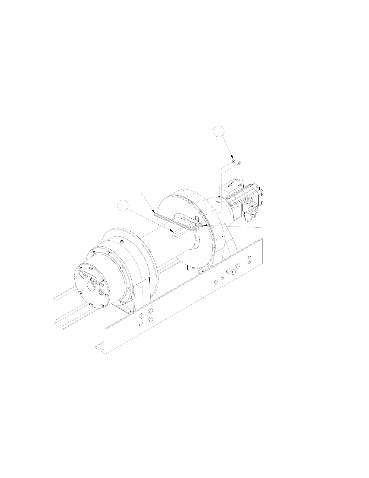
INSTRUCTIONS FOR DISASSEMBLY
1. Remove wire rope from drum.
2. Drain oil from winch by removing (2) plugs #54, removing the lower plug first.
3. When replacing lubricant, use 264 oz of applicable lube for your climate form table on page 5,
adding 4 oz at #44 and the remaining at # 55.
4. Remove (2) nuts #208b from air cylinder #208a. Air cylinder may now be removed. If needed,
mounting bracket #201 may be removed by removing pin #204 from pin #205 and then sliding
pin out of mounting bracket. Brake band #5 may be expanded over drum flange to barrel for
easiest removal.
44
55
54
54
14
38
5
NOTE:
BRAKE BAND FITS
OVER DRUM FLANGE
208b
201
204
205
208a
6 OM-914207-0211-D
Page 9

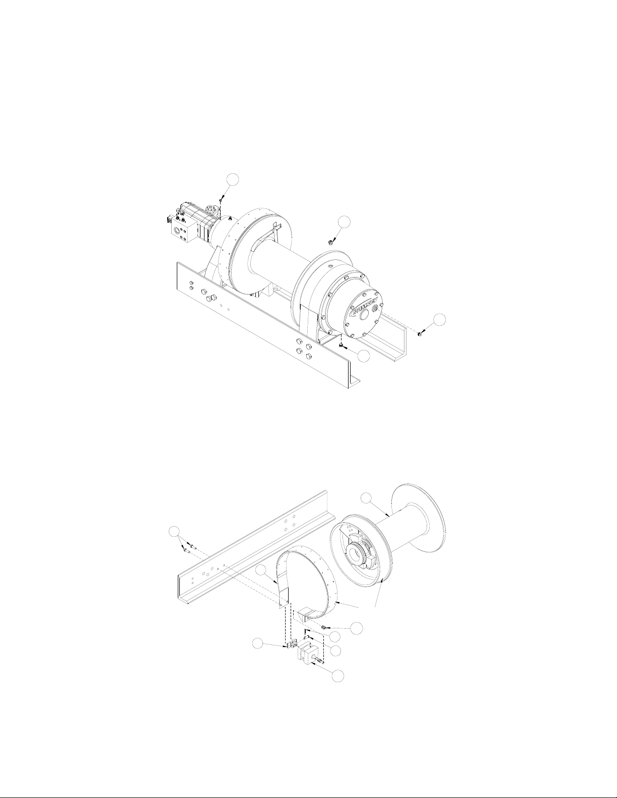
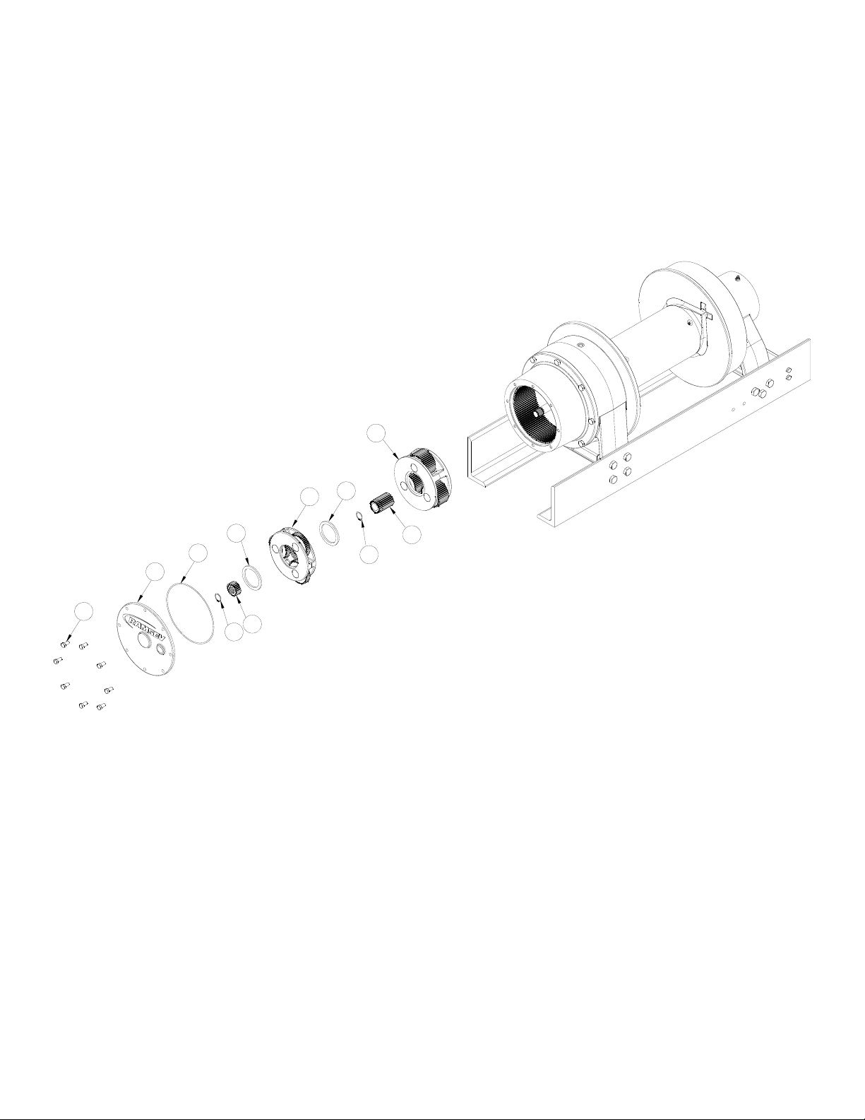
5. Remove motor #45 from winch by first disconnecting hydraulic lines (see page 17), solenoid
wires, and then remove (4) bolts #73. O-ring #72 may now be removed.
6. Remove brake cover #42 by removing (4) bolts #66. The cover is spring loaded, use care
when removing. Remove o-ring #46 then springs #61 may be removed; residual oil may be
present in the brake housing.
7. Remove piston #11 including o-rings and backup rings #47, #48, #49, and #50 by using a
momentary puff of compressed air into the brake port located on top of the end bearing.
Capture the piston by placing a shop rag over the opening prior to using air.
8. Remove the sprag brake hub assembly #40, (7) stator plates #12, (6) disc brakes #13, and the
spacer #28. The sprag brake hub assembly #40 is not a serviceable part, if damaged a
replacement assembly should be ordered.
28
40
13
12
48
47
11
49
50
61
46
42
66
72
45
73
63
7 OM-914207-0211-D
Page 10
9. Remove (8) cover bolts #36; cover #10, and o-ring #51.
10. Remove snap ring #58, and sun gear #17.
11. The planetary carrier assembly #4 may now be removed along with (2) spacers #24.
12. Remove second snap ring #58 and intermediate sun gear #16.
13. Planetary carrier assembly #3 may now be removed.
3
24
4
24
51
10
36
17
58
16
58
8 OM-914207-0211-D
Page 11
14. Using a nylon strap, support ring gear #20 from a hoist or boom, this ring gear is heavy.
Remove (8) bolts #37 leaving the top most bolt for last. Remove the final bolt while supporting
ring gear. Set ring gear aside. Remove the o-ring #52.
15. Remove spacer #26 and the output sun gear #15.
16. Using a large pair of snap ring pliers remove the snap ring #60 from the shaft located inside
the planetary carrier assembly #2.
17. Using a nylon strap and hoist slide the output planetary carrier #2 from the ring gear housing.
The output planetary carrier is heavy.
18. Remove the spacer #27.
2
60
15
52
20
37
26
27
9 OM-914207-0211-D
Page 12

19. Remove the clutch cylinder #1 by removing the (2) cotter keys #204 and (2) pins #206 from
either end of the air cylinder #207.
20. The clutch cylinder support angle #8 can be removed by removing the four bolts #66 and nuts
#65 attaching it to the mounting angles.
21. Remove the clutch yoke #29 by removing center pivot bolt #21 and nut #65.
NOTE:
VIEW SHOWN LESS DRUM AND ANGLE CUT AWAY FOR CLARITY
21
65
66
29*
1
* CLUTCH YOKE #29 SHOWN REMOVED
AND PARTIALLY INSTALLED
FOR CLARITY
206
204
204
207
29*
206
209
65
66
202
8
10 OM-914207-0211-D
Page 13

22. By removing snap ring #58 and ball bearing #31, the input shaft #22 may be removed.
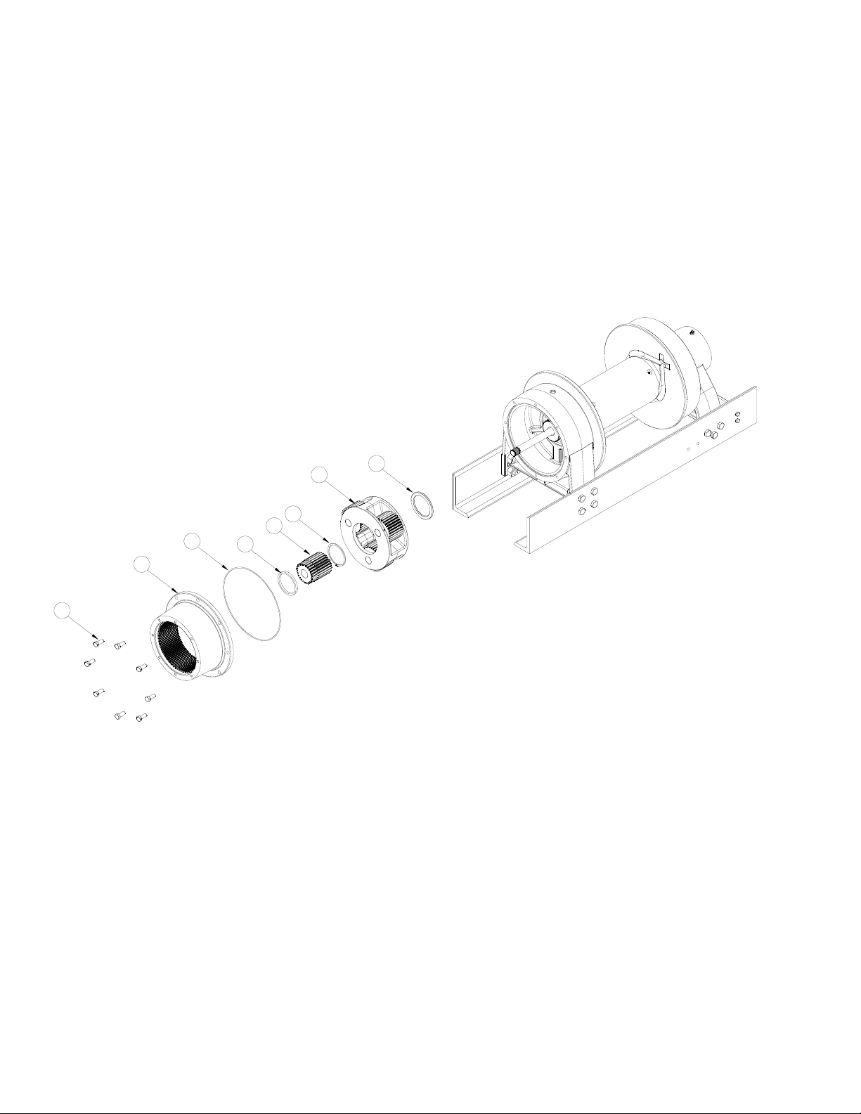
23. To remove the motor end bearing #18, support drum #14 with a nylon strap or chain and hoist.
Lift on the drum to tension the strap. Remove (6) bolts #67 and (6) nuts #68 attaching the end
bearing to the mounting angles #6 and #7. The motor end bearing #18 will be supported on the
output shaft end and may be slid off using a nylon strap and hoist to lift it.
14
67
18
22
68
31
58
7
6
67
11 OM-914207-0211-D
Page 14

24. While continuing to support the drum #14, remove the clutch #9, snap ring #60 and spacer
#25.
25. The output shaft #23 may be slid from the drum assembly.
26. The drum #14 is now supported only by the nylon strap and maybe removed as needed.
27. The (2) bushings #34 may be pressed from the drum if replacement is necessary.
14
34
23
25
60
9
34
12 OM-914207-0211-D
Page 15

28. To remove gear end bearing #18, from mounting angles #6 and #7, first remove (4) 7/8-9NC
bolts #67 and (4) nuts #68 from each angle. Shaft oil seal #56 and end bearing bushing # 33
can be removed and replaced at this time, if necessary.
67
7
33
56
6
18
68
67
68
13 OM-914207-0211-D
Page 16

DISASSEMBLY OF CARRIER ASSEMBLY
Carrier assemblies may be purchased as a complete assembly (see pg. 19) or parts may be
purchased individually (see pg 16). If purchasing individual parts, it will be necessary to
disassemble the gear carrier as outlined below. Disassembly/ assembly of carriers utilizes the
same process for input carrier assembly #4, intermediate carrier assembly #3, and output
carrier assembly #2. Detail shown below is for intermediate carrier assembly#3. Please see
page 16 for detailed parts list and drawings of individual carriers.
1. Carefully drive roll pin #112 into carrier pin #111 so that it is captured within carrier pin #111
but not touching the opposite side of the intermediate carrier #102.
2. Tap carrier pin #111 to remove it from the intermediate carrier #102.
3. Place a plastic pail in a position to catch bearings #110, spacer #108 and washers #115, then
slide the gear #105 from the carrier assembly #102.
4. Remove the roll pin #112 from the carrier pin #111.
5. Repeat this process for the two remaining gears in the carrier.
112
115
105
110
108
110
115
102
INTERMEDIATE CARRIER
111
14 OM-914207-0211-D
Page 17

ASSEMBLY OF CARRIER ASSEMBLY
1. Place carrier #102 on flat clean surface.
2. A tool the width of the gear #105 and the diameter of the carrier pin #111 is helpful to install
needle bearings #110.
3. Place the gear #105 on a flat thin clean metal plate; metal plate should not be thicker than
thrust washer #115 and should be able to slide into gear pocket of carrier. Grease the inside of
gear and insert the greased tool described above into gear.
4. Place one row of needle bearings #110 into gear #102 carefully sliding them down the gap
between the tool and the gear so they stand vertically.
5. If more than one row of needle bearings is required, as shown in intermediate carrier, install
spacer #108, and the next row of needle bearings #110 as detailed in step 4 above until all
bearings are installed.
6. With tool remaining in place slide the gear #105 (resting on the thin plate) into position in the
carrier #102.
7. Place thrust washer #115 on top of gear #105. Insert planet pin #111 into carrier #105
8. Turn carrier #102 on its side so that the gear is on top. Remove the thin plate. Remove tool by
pushing planet pin #111 into carrier #102 until planet pin is at least half way past the last row of
bearings #110. The tool may now be removed completely.
9. Insert a thrust washer between gear #105 and carrier #102. Completely insert planet pin #111
into carrier #102 using care to align the roll pin hole in planet pin #111 with the roll pin hole in
the carrier #102.
10. Drive roll pin #112 into carrier #102 until roll pin #112 is flush with surface of the carrier #102.
11. Repeat this process to install the two remaining gears into the carrier.
15 OM-914207-0211-D
Page 18

CARRIER ASSEMBLIES
115
Input Carrier*
112
106
109
115
113
101
* Input Gear Assembly may be purchased under part n umber 296672
Item Qty Part No. Description
101 1 317018 Input Carrier
102 1 317019 Intermediate Carrier
103 1 317020 Output Carrier
104 3 334202 Output Planet Gear
105 3 334204 Intermediate Planet Gear
106 3 334206 Input Planet Gear
107 6 362306 Output Spacer
108 3 362307 Intermediate Spacer
109 102 402135 Input Needle Roller Beari ng
110 204 402136 Intermediate Needle Roller Bearing
110 306 402136 Output Needle Roller Bearing
111 3 470113 Intermediate Carrier Pin
112 9 470036 Input, Inter. & Output Roll Pin
113 3 470111 Input Carrier Pin
114 3 470115 Output Carrier Pin
115 18 518067 Input, Inter. & Output Thrust Washer
112
105
115
102
* Intermediate Gear Assembly may be purchased under part number 296671
INTERMEDIATE CARRIER*
110
108
110
111
115
110
110
115
107
107
* Output Gear Assembly may be purchased under part number 296670
110
114
112
OUTPUT CARRIER*
104
115
103
16 OM-914207-0211-D
Page 19

21
30
HOSE HOOKUP
21
41
41
69
53
32
41
69
21
41
32
20
17 OM-914207-0211-D
Page 20

PARTS DRAWING
6015
2652
2037316
24
4581758
24
51
54
36
10
2
55
44
19
27
54 68
34 23
62
33
6
56
67
25 60
1
18
68
57 29
21
22
9
12
28
58
31
65
65
1
74
6111
474813
35
8
44
5
7
66
67
38
63
73
45
72
66
42
46
50
49
NOTES:
1. ITEM 1 - AIRCYLINDER KIT CONTAINS FASTENERS AND
CYLINDERS FOR CLUTCH AND BAND BRAKE.
2. ITEM 63 CONTAINS FASTENERS FOR BRAKE VALVE.
3. HOSE KIT CONTAINS FITTINGS AND HOSE.
34
14 43
62
40
18 OM-914207-0211-D
Page 21

PARTS LIST
ITEM QTY PART NO DESCRIPTION ITEM QTY PART NO DESCRIPTION
1 1 256131 AIR CYLINDER KIT 38 2 414551 BOLT-1/2-13NCX1 1/2LG HXHD,GR5/FB
2 1 296670 OUTPUT CARRIER ASSEMBLY 39 1 432018 FITTING JIC O-RING EL
3 1 296671 INTERMEDIATE CARRIER ASSEMBLY 40 1 296952 SPRAG BRAKE HUB ASSEMBLY
4 1 296672 INPUT CARRIER ASSEMBLY 41 4 432023 FITTING JIC O-RING NIPPLE
5 1 299748 BAND BRAKE 42 1 438043 BRAKE COVER
6 1 303150 LH MOUNTING ANGLE 43 2 456001 FITTING-LUBE, 3/16 DRIVE FIT, SHORT
7 1 303151 RH MOUNTING ANGLE 44 2 456008 FITTING-RELIEF1/8-27NPTF, 15 PSI MAX
8 1 312574 CLUTCH CYLINDER SUPPORT BRACKET 45 1 458164 MOTOR-HYD, 3.21/5.78 CU.IN., 2 SPD
9 1 324510 CLUTCH 46 1 462063 O-RING 2-165
10 1 328167 GEAR HOUSING COVER 47 1 462082 O-RING 2-358
11 1 330016 BRAKE PISTON 48 1 462083 BACK UP RING
12 7 330017 STRATOR PLATE 49 1 462084 O-RING 2-362
13 6 330018 DISC-BRAKE 50 1 462085 BACK UP RING
14 1 332229 DRUM 51 1 462092 O-RING 2-275
15 1 334198 GEAR-SUN 52 1 462093 O-RING 2-280
16 1 334199 GEAR-SUN 53 1 432053 FITTING JIC O-RING NIPPLE
17 1 334200 GEAR-SUN 54 2 468041 PLUG, -8 SAE, 3/4"-16 UNF
18 1 338378 END BEARING-MOTOR SIDE 55 1 468042 REDUCER-3/4-16 SAE O-RING X 1/8NPTF
19 1 338380 END BEARING-GEAR SIDE 56 1 486087 SEAL-OIL-SHAFT-SKF 42419
20 1 338381 HOUSING-GEAR 57 1 486088 SEAL-OIL-SHAFT-SKF 38653
21 1 414543 CAPSCREW-1/2-13NCX3LG,HXHD, GR 5 58 3 490006 SNAP RING 5100-125
22 1 357529 INPUT SHAFT 59 1 432054 FITTING JIC SWIVEL EL
23 1 357530 SHAFT-OUTPUT 60 2 490056 SNAP RING 5100-425
24 2 362301 SPACER 61 12 494129 SPRING-BRAKE
25 1 362302 SPACER-SHAFT 62 1 514023 U-BOLT W/2 NUTS
26 1 362303 SPACER 80K WINCH 63 1 516048 COUNTER BALANCE BLOCK
27 1 362304 SPACER
28 1 362305 SPACER 65 5 418069 NUT-1/2-13NC HEX REG,Z/P
29 1 370062 YOKE-SHIFTER 66 8 414556 CAPSCREW-1/2-13NCX1 3/4 HXHD GR.5
30 1 432048 FITTING JIC SWIVEL TEE 67 14 414790 BOLT-7/8-9NC X 3.25 LG,HXHD,GR8, Z/P
31 1 402132 BALL BEARING 68 14 418108 NUT-7/8-9NC HEX REG Z/P
32 2 432049 FITTING JIC BRANCH TEE 69 1 509137 HOSE
33 1 412119 END BEARING BUSHING 70 2 509140 HOSE
34 2 412120 DRUM BUSHING 71 3 509141 HOSE
35 1 412121 END BEARING BUSHING 72 1 462081 ORING 2-159
36 8 414521 CAPSCREW-1/2-13NCX1LG HXHD GR 5 73 4 414578 BOLT-1/2-13NC X 1 1/4 LG, HXHD, GR 5
37 8 414658 BOLT-5/8-11NCX1 1/2LG,HXHD,Z/P,GR.5 74 1 468016 PIPE PLUG 1/8-27 NPTF
19 OM-914207-0211-D
Page 22

AIR CYLINDER KIT #256131 PARTS LIST
202
202
209
203
204
206
204
201
205
204
206
203
207
ITEM QTY PART NO DESCRIPTION
201 1 408422 MOUNTING BRACKET
202 2 418067 NUT-1/2-20NF HEX JAM
203 2 418223 WASHER-1/2 USS FLAT
204 3 424005 COTTER PIN- 1/8 DIA X 1 LG
205 1 424027 CLEVIS PIN-1/2 SHAFT DIA X 1 1/2 LG
206 2 424205 CLEVIS PIN-1/2 SHAFT DIA X 1 23/64 LG
207 1 433031 AIR CYLINDER
208 1 433032 AIR CYLINDER
209 1 448108 EYE BOLT
208
20 OM-914207-0211-D
Page 23

DIMENSIONAL DRAWING
CONNECT TO 2 SPEED SWITCH
SAE #16 O-RING PORT
12VDC SOLENOID
1" LINE SIZE
PAY-OUT PORT
13.00
330,20
10.21
259,21
50.61
1285,45
49.47
1256,56
20.41
518,42
GREASE ZERK
LUBRICATE AS NOTED IN
INSTRUCTION MANUAL
Ø9.00
228,60
14.81
376,18
Bolt Size
(inch es)
Thd s Per
Inch
Bolt Torque (ft-lb)
SAE Gr ade 5 SAE Gra de 8
7/16 14 54 78
1/2 13 78 119
5/8 11 154 230
3/4 10 257 380
7/8 9 382 600
1 8 587 700
Ø21.00
533,40
25.25
641,36
23.93
607,90
SAE #16 O-RING PORT
1" LINE SIZE
PAY-IN PORT
DRUM
59.00
1498,60
C
L
8.00
203,20
4.00
101,60
CLUTCH DIS-ENGAGE PORT
1/8 NPT FITTING SIZE
CONNECT TO CLUTCH VALVE
100 PSI AIR PRESSURE MINIMUM
20.00
508,00
BAND BRAKE ENGAGE PORT
1/4 NPT FITTING SIZE
CONNECT TO BAND BRAKE VALVE
100 PSI AIR PRESSURE MINIMUM
21 OM-914207-0211-D
Page 24

Limited Warranty
RAMSEY WINCH warrants each new RAMSEY WINCH to be free from defects in
material and workmanship for a period of one (1) year from date of purchase.
The obligation under this warranty, statutory or otherwise, is limited to the
replacement or repair at the Manufacturer's factory, or at a point designated by the
Manufacturer, of such part that shall appear to the Manufacturer, upon inspection of
such part, to have been defective in material or workmanship.
This warranty does not obligate RAMSEY WINCH to bear the cost of labor or
transportation charges in connection with the replacement or repair of defective
parts, nor shall it apply to a product upon which repair or alterations have been
made, unless authorized by Manufacturer, or for equipment misused, neglected or
which has not been installed correctly.
RAMSEY WINCH shall in no event be liable for special or consequential damages.
RAMSEY WINCH makes no warranty in respect to accessories such as being
subject to the warranties of their respective manufacturers.
RAMSEY WINCH, whose policy is one of continuous improvement, reserves the
right to improve its products through changes in design or materials as it may deem
desirable without being obligated to incorporate such changes in products of prior
manufacture.
If field service at the request of the Buyer is rendered and the fault is found not to
be with RAMSEY WINCH's product, the Buyer shall pay the time and expense to
the field representative. Bills for service, labor or other expenses that have been
incurred by the Buyer without approval or authorization by RAMSEY WINCH will not
be accepted.
See warranty card for details.
Ramsey Winch Company
Post Office Box 581510
Tulsa, Oklahoma 74158-1510
Telephone: (#918) 438-2760 FAX: (#918) 438-6688
OM-914207-0211-D
 Loading...