

Page 1
Congratulations
You have purchased the finest winch available in its service class. It features a highly efficient 3 stage
planetary gear set which transmits torque from a permanent magnet motor. A safe positive clutch allows
free spooling for quick cable deployment. Your Ramsey winch was designed and manufactured to provide
you with the utmost in utility. As with any device that combines power and movement in its use, there are
dangers if improperly used.
At the same time, there are easier and faster ways for getting the job done if certain precautions are taken
first. Please read this manual carefully. It contains useful ideas in obtaining the most efficient operation
from your Ramsey Winch and safety procedures you need to know before beginning use. When you follow our guidelines for operation, your Ramsey winch will give you many years of satisfying service. Thank
you for choosing Ramsey. You will be glad you have one working for you.
Please Note: Ramsey UTV 5000 winches are designed primarily for ATV/UTV use. This winch is not designed to be used in industrial
applications (car haulers /carriers, wreckers, hoisting, etc.), and Ramsey does not warrant it to be suitable for such use. Ramsey makes
a separate, complete line of winches for industrial/commercial use. Please contact the factory for further information.
CAUTION: READ AND UNDERSTAND THIS MANUAL BEFORE INSTALLATION AND OPERATION OF WINCH. SEE SAFETY PRECAUTIONS.
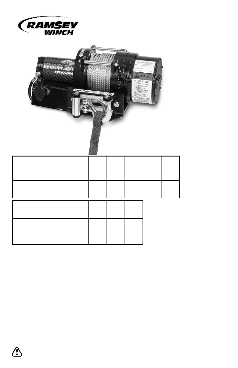
Layer of Cable 123456
(lbs) 5,000 4,200 3,600 3,200 2,800 2,600
(kg) 2,270 1, 900 1,630 1,450 1,270 1, 180
(ft)5 1530405560
(m) 1.5 4.5 9 12.1 16.7 18.2
(lbs)
NO
1,000 3, 000 5,000
(kg)
LOAD
454 1,363 2, 272
(FPM )
15 11 8 5
(MPM )
4.5 3.3 2.4 1.5
Amp Draw
(12v)
45 100 155 230
Line Speed First
Layer
Line Pull First
Layer
Rated Line Pull
Per Layer
Cumulative Cable
Capacit y Per
Layer*
Ramsey Winch Company
OWNER'S MANUAL
UTV HONCHO 5000 Winch
* Depends on cable being uniformly wound
onto drum.
NOTE: Fairlead does not attach directly to winch.
Page 2
Safety Precautions To Guard
Against Possible Injury.....
A. Keep yourself and others a safe distance to
the side of the cable when pulling under load.
B. Do not step over a cable, or near a cable
under load.
C. Use supplied hook strap when handling hook
for spooling wire rope.
D. Do not use ATV to pull a load on the winch
cable. This could result in cable breakage
and/or winch damage
E. Use a heavy rag or gloves to protect hands
from burrs when handling winch cable.
F. Apply blocks to wheels when ATV is on an
incline.
G. Winch clutch should be disengaged when
winch is not in use and fully engaged when in
use.
H. Modification, alteration, or deviation to the
winch should only be made by Ramsey Winch
Company.
I. Keep the duration of your pulls as short as
possible. If the motor becomes uncomfortably
hot to the touch, stop and let it cool for a few
minutes. Do not pull more than one minute at
or near the rated load. Do not maintain power
to the winch if the motor stalls. Electric
winches are for intermittent usage and should
not be used in constant duty applications.
J. Do not use winch in hoisting applications due
to required hoist safety factors and features.
K. Do not exceed maximum line pull ratings
shown in tables. Shock loads must not
exceed these ratings.
L. To respool correctly, it is necessary to keep a
slight load on the cable. Do not allow the
cable to slip through your hand and do not
approach the winch too closely. When all the
cable except a few feet is in, stop and finish
spooling in cable by rotating the drum by hand
with clutch disengaged. Always use hook
strap to hold hook when spooling.
Contents
Performance Specifications . . . . . . . . . .cover
Safety Precautions . . . . . . . . . . . . . . . . . . . .2
Tips for Safe Operation . . . . . . . . . . . . . . . .3
Techniques of Operation . . . . . . . . . . . . . . .3
General Installation . . . . . . . . . . . . . . . . . . .4
Toggle Switch Installation . . . . . . . . . . . . . .4
Operating Instructions . . . . . . . . . . . . . . . . .5
Maintenance . . . . . . . . . . . . . . . . . . . . . . . .5
Cable Installation . . . . . . . . . . . . . . . . . . . . .5
Trouble Shooting Guide . . . . . . . . . . . . . . . .6
Winch Parts List . . . . . . . . . . . . . . . . . . .8-11
Warranty . . . . . . . . . . . . . . . . . . .back cover
2
Page 3
Tips for Safe Operation
Don't underestimate the potential danger in winching operations. Neither should you fear them. Do
learn the basic dangers and avoid them.
Observe spooling of cable onto drum. Side pulls
can cause cable to pileup at one end of the drum.
To correct uneven stacking, spool out that section
of the cable and move it to the other end of the
drum and continue winching. Uneven spooling
which causes cable pileup can interfere with the
winch tie rods causing damage to the winch.
Never connect the hook back to the cable. This
causes cable damage. Always use a sling or
chain of suitable strength.
Observe your winch while winching. If possible,
while standing at a safe distance. If you use ATV
drive to assist, stop and get off every few feet to
assure the cable is not piling up in one corner.
Jamming cable can break your winch.
Do not attach tow hooks to winch mounting apparatus. They must attach to ATV frame.
When double lining during stationary winching,
the winch hook should be attached to the chassis
of the ATV. Since the greatest pulling power is
achieved on the innermost layer of your winch, it
is desirable to pull off as much line as you can for
heavy pulls. If this is not practical, use a snatch
block and double line arrangement.
Neat, tight spooling avoids cable binding which is
caused when a load is applied and the cable is
pinched between two other wraps of cable. If this
happens, alternately power the winch in and out a
few inches. Do not attempt to work a bound
cable under load, free by hand.
Techniques of Operation
The best way to get acquainted with how your
winch operates is to make a few test runs before
you actually need to use it. Plan your test in
advance. Remember you hear your winch as well
as see it operate. Get to recognize the sound of a
light steady pull, a heavy pull, and sounds caused
by load jerking or shifting. Soon you will gain
confidence in operating your winch and its use
will become second nature with you.
Your winch will not only pull your ATV up or ease
your ATV down a steep grade, it will also pull
another ATV or a load while your ATV is anchored
in a stationary position.
When pulling a heavy load, place a blanket, jacket
or tarpaulin over the cable five or six feet from the
hook. It will slow the snap back in the event of a
broken cable.
Use the ATV wheel power to help the winch, but
don't overtake the winch line. Plan your pull.
You can't always hook up and pull out in one step.
Examine all the areas for anchoring possibilities
as well as leverage situations, direction, and goal.
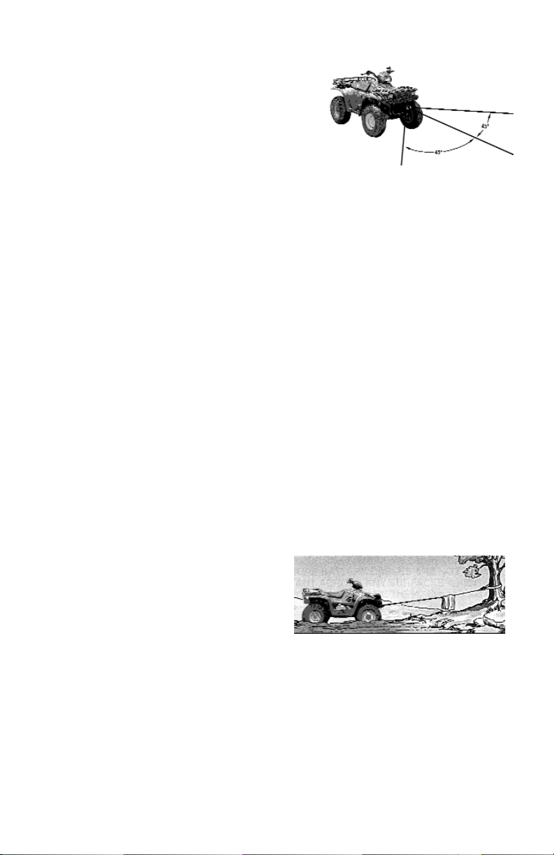
Winches equipped with cable guide fairleads can pull
from several directions. Pull from an angle only to
straighten up the ATV--otherwise you can damage structural members or other parts of your ATV and cause
excess cable buildup on one end of the winch drum.
For basic self-recovery, anchor to a tree or heavy rock.
When anchoring to a tree, always use a tree trunk protector.
3
Page 4
General Installation
The winch shown in this owners manual is solely
and exclusively designed for ATV mounted, nonindustrial applications. All other applications will
void warranty.
Install Winch and Mounting Kit according to
instructions supplied with Mounting Kit. Install
winch and roller fairlead to mounting kit using
hardware supplied with winch. Tighten mounting
bolts to 34 ft-lbs torque.
It is very important that the winch be mounted on a flat surface, with the cable feeding
from the bottom of the drum.
Toggle Switch Installation
Do not attach motor and battery leads until
instructed to do so.
Before beginning Installation:
• Disengage winch clutch.
• Locate and mark mounting location for
toggle switch.
1. Route red, yellow, and green wires from solenoid to toggle switch location. Make sure that
wires are not drawn taut against any surfaces
that might damage them.
2. Drill 1/2” hole in location for toggle switch.
3. Insert switch through hole.
4. Place directional plate over switch and secure
using knurled nut. Using wrench, tighten
backup nut securely against surface where
hole was drilled. Make sure directional plate
is installed in the same direction as the toggle
switch movement.
5. Place rubber boot over switch and tighten
securely.
6. Connect red wire to center spade on toggle
switch. Connect green wire to the toggle
switch terminal in the “OUT” position.
Connect the yellow wire to the toggle switch
terminal position in the “IN” position.
When finished, connect the Red battery lead from
the solenoid to the Positive (+) terminal of the
vehicle battery. Connect the Black battery lead to
the Negative (-) terminal.
Free-spool a length of cable from the winch.
Engage the clutch, and operate the toggle switch
in the IN and OUT direction and confirm that the
winch operates correctly.
If the winch spools cable in the opposite direction
from what is indicated on the directional plate,
reverse the yellow and green wires.
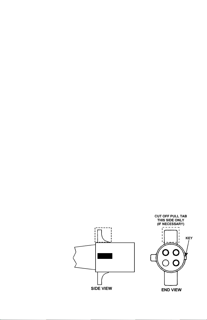
Remote Control Switch Installation
Connect the Red battery lead from the solenoid to
the Positive (+) terminal of the vehicle battery.
Connect the Black battery lead to the Negative (-)
terminal.
For some mounting kits, it may be necessary to
alter the remote control switch’s plug by cutting
off one of the pull tabs. Do not alter the plug
until you confirm that it is necessary. See the
diagram below.
4
Page 5

Operating Instructions
The winch clutch allows rapid unspooling of the
wire rope for hooking onto the load or anchor
point. The clutch shifter tab is located on the
gear-housing end of the winch and operated as
follows:
1. To disengage the clutch, move the clutch
shifter tab to the “OUT” position. Wire rope
may now be free-spooled off the winch.
2. To engage the clutch, move the clutch shifter
tab to the “IN” position. The winch is now
ready for pulling.
Your battery must be kept in good condition. A
fully charged battery and proper connections are
essential. Run the vehicle engine during winching
operations to keep battery charged.
The remote control switch is waterproof. It has
push button stations on either side. It is designed
this way to prevent quick winch reversals, which
lead to solenoid failure.
Make sure the motor has stopped fully before
reversing. To actuate winch simply plug remote
control switch into receptacle in black solenoid
cover of winch.
Run winch forward and reverse to check connection and to determine winch operating directions.
Snap appropriate "IN" and "OUT" disc into proper
thumb cavity. The switch is also color coded to
aid you in not having to guess at the direction
your winch will run. DO NOT LEAVE SWITCH
PLUGGED IN WHEN WINCH IS NOT IN USE.
Maintenance
Corrosion on electrical connections will reduce
performance or may cause a short. Clean all connections. In salty environments use a silicone
sealer to protect from corrosion.
To minimize corrosion of the internal motor components that may occur due to condensation,
power the winch in or out periodically. Energizing
the motor will generate heat, which will help dissipate any moisture buildup in the motor. This
should be performed at periodic intervals (such
as with each oil change to your vehicle).
Note: Refer to Troubleshooting Guide if the motor
has been submerged.
All moving parts in the winch are permanently
lubricated with broad temperature range lithium
based grease. Under normal conditions factory
lubrication will suffice.
Lubricate cable periodically using light penetrating
oil. Inspect for broken strands and replace if necessary. If the cable becomes worn or damaged, it
must be replaced.
Cable Installation
Note: Cable should be installed so that it
feeds from the bottom of the drum.
It is not necessary to disassemble the winch or
remove it from where it is mounted to replace the
cable.
Unwind the new cable by rolling it out along the
ground to prevent kinking.
Remove old cable and observe the manner in
which it is attached to the cable drum. Loosen but
do not remove the cable anchor.
Before installing the new cable assembly, make
sure the end of the cable is squarely cut and
wrapped with tape to prevent fraying.
Feed the taped end of the cable through the fairlead and under the drum.
Slide the cable to the end of the slot on the drum
flange under the cable anchor.
Tighten the cable anchor securely to the drum so
that the cable is held securely.
Wind five wraps of cable onto the drum by rotating the drum while free-spooled. Wind on the rest
of the cable by pulling in a light load to keep tension constant. Allow the cable to swivel by using
a length of chain or a block between the cable
hook and the load.
5
Page 6

UTV 5000 Trouble Shooting Guide
CONDITIONS POSSIBLE CAUSE CORRECTION
MOTOR RUNS IN ONLY ONE Defective solenoid or stuck solenoid. Jar solenoid assembly to free contacts.
DIRECTION Check each solenoid by applying
+12 volts to coil terminal (it should
make an audible click when energized).
-------------------------------------------------------------------------------------------------------------------------------------------
MOTOR RUNS EXTREMELY Long period of operation Cooling-off periods are essential to
HOT prevent overheating.
-------------------------------------------------------------------------------------------------------------------------------------------
MOTOR RUNS, BUT WITH Bad connection Check battery cable for corrosion;
INSUFFICIENT POWER clean and grease
OR WITH LOW LINE SPEED
Insufficient battery Test for faulty vehicle battery.
Insufficient charging system Replace with larger capacity charging
system.
-------------------------------------------------------------------------------------------------------------------------------------------
MOTOR RUNS, BUT DRUM Clutch not engaged If clutch engaged but symptoms still
DOES NOT TURN exist, it will be necessary to disassem-
ble winch to determine cause and
repair.
-------------------------------------------------------------------------------------------------------------------------------------------
MOTOR WILL NOT OPERATE Loose connections. Check all electrical connections from
the battery to the motor.
Defective solenoid or stuck solenoid. Jar solenoid assembly to free contacts.
Check solenoid by applying 12 volts to
coil terminal (it should make an audible
click when energized).
Defective remote control switch Disengage winch clutch, remove remote
control switch plug from the socket and
jump pins at 8 and 4 o’clock. Motor should
run. Jump pins at 8 and 10 o-clock. Motor
should run.
Defective motor If solenoids operate, check for voltage
at armature post; replace motor.
-------------------------------------------------------------------------------------------------------------------------------------------
MOTOR WATER DAMAGED Submerged in water or water Allow to drain and dry thoroughly, then
from high pressure car wash Run motor without a load in short
bursts to dry windings.
--------------------------------------------------------------------------------------------------------------------------------------------
CABLE DRUM WILL NOT Clutch not disengaged Check clutch operation according to
FREE-SPOOL OR IS nameplate. Make sure clutch shifter tab is
DIFFICULT TO FREE-SPOOL fully at “OUT” position.
Winch not mounted squarely causing Check that Mounting Kit instructions have
end bearing to bind drum been followed.
Some or all of the (6) 1/4-20NC Remove gear housing cover and all gears
capscrews attaching the ring gear from inside the gear housing. Disengage the
retainer are too tight (see Parts clutch and check to see that the ring gear
Diagram, following page). will rotate by hand. If not, using a hex (allen)
wrench, slightly loosen all the capscrews and
then snugly re-tighten them in a criss-cross
pattern, but do not over tighten. The ring gear
must rotate by hand. Re-assemble the winch.
6
Page 7

7
NOTES
Page 8

8
40
6
15
9
35
35
33
*4
21
36
37
34
14
11
29
1
38
28
10
15
12
2
39
23
13
38
17
16
38
3
30
7
32
8
31
27
22
24
25
19
26
18
5
25
24
20
UTV 5000 PARTS DIAGRAM
Page 9

9
Item
No.
Qty. Part No. Description
Item
No.
Qty. Part No. Description
1 1 247004 Gear Carrier Assembly - Input 20 1 414830 Capscrew - 1/4-20NC x 3/8 Button Hd.
2 1 247005 Gear Carrier Assembly - Intermediate 21 6 414861 Capscrew - 1/4-20NC x 3/4 Flat Soc Hd Nylok
3 1 247006 Gear Carrier Assembly - Output 22 2 415007 Capscrew M6 x 1 x 107mm Hx Hd Z/P
4* 1 251110 Switch Assembly - 12 ft 23 6 416273 Screw - #6-32NC x 3/8
1 504024 Toggle Switch Assembly 24 6 418035 Nut - 3/8-16NC Hx reg Z/P
5 1 251236 Roller Fairlead Assembly 25 6 418177 Lockwasher 3/8
6 1 251282 Cable Assembly - 60' x 7/32" Dia. 26 4 418181 Washer - 3/8 ID SAE Flat Z/P
7 1 256127 Motor/End Bearing Assembly 27 2 419004 Locknut M6 x 1 Hx Hd w/Nylon Insert
8 1 278194 Solenoid Assembly (Pendant Switch) 28 1 442207 Gasket - Gear Housing Cover
278193 Solenoid Assembly (Toggle Switch) 29 1 444048 Gear - Output Sun
9 1 296637 Brake Assembly 30 1 448071 Cable Anchor
10 1 332213 Drum - Cable 31 2 448105 Tie Bar
11 1 334143 Gear - Ring 32 1 470050 Roll Pin
12 1 334145 Gear - Intermediate Sun 33 1 477002 Locking Ring
13 1 334153 Gear - Input Sun 34 1 477013 Cam Ring
14 1 338249 End Bearing 35 2 477004 Ring - Half
15 2 412056 Bushing - Drum 36 1 479007 Retainer - Ring Gear
16 1 412061 Bushing - Shaft 37 6 494077 Spring
17 1 413018 Cover - Gear Housing 38 3 518020 Thrust Washer
18 2 414314 Capscrew - 3/8-16NC x 1 Hx Hd Z/P Gr5 39 1 518027 Thrust Disc
19 4 414316 Capscrew - 3/8-16NC x 1 1/4 Hx Hd Z/P Gr5 40 1 452005 Shifter Lever
* Winch includes either a 12' Pendant Remote Control Switch or a Dash-Mount Toggle Switch
Page 10

10
15
1
5
19
12
10
8
6
18
413
15
17
16
3
11
10
7
14
20
2
9
9
16
11
10
1
5
Item
No.
Qty.
Req'd
Part No. Description
1 2 264002 Copper Strap
2 1 289090 Wire Assembly - #10 Ga. Black Ground
3 1 289091 Wire Assembly - Female Conn to Solenoid
4 1 289092 Wire Assembly - #6 Ga. Black 3-1/2"
5 2 289095 Wire Assembly - #6 Ga. Black 6"
6 1 408087 Solenoid Bracket
7 1 413019 Solenoid Cover
8 4 416216 Screw - #10-24NC x 1/2 Slot Z/P
9 2 416227 Screw - #10-24NC x 3/4 F/B
10 6 418004 Nut - #10-24NC Reg Z/P
11 4 418140 Washer - #10 Flat Z/P
12 2 418141 Lockwasher - #10 Med
13 1 418165 Washer - 5/16 Shake Proof
14 1 430013 Connector - Female Receptacle
15 2 440071 Terminal Tab
16 2 440110 Solenoid 12V
17 1 440111 Strap
18 1 440295 Wire Assembly - Battery #4 Ga. 96" Red
19 1 440296 Wire Assembly - Battery #4 Ga. 96" Black
20 1 482029 Cover - Female Receptacle
Solenoid Assembly 278194 Parts List
(Pendant Switch)
Page 11

17
10
20
18
1
5
13
15
23
12
12
9
8
4
2
19
21
19
3
14
13
18
1
5
22
16
11
9
2
3
18
7
8
18
6
11
Solenoid Assembly 278193 Parts List
(Toggle Switch)
Item
No.
Qty.
Req'd
Part No. Description
1 2 264002 Copper Strap
2 1 289090 Wire Assembly - #10 Ga. Black Ground
3 2 289091 Wire Assembly - Female Conn to Solenoid
4 1 289092 Wire Assembly - #6 Ga. Black 3-1/2"
5 2 289095 Wire Assembly - #6 Ga. Black 6"
1 299741 Wire Assembly - Consists of:
6 #18 Ga. Green Wire 123" long
7 #18 Ga. Yellow wire 123" long
8 #18 Ga. Red wire 123" long
9 1 408087 Solenoid Bracket
10 1 413019 Solenoid Cover
11 4 416216 Screw - #10-24NC x 1/2 Slot Z/P
12 2 416227 Screw - #10-24NC x 3/4 F/B
13 6 418004 Nut - #10-24NC Reg Z/P
14 4 418140 Washer - #10 Flat Z/P
15 2 418141 Lockwasher - #10 Med
16 1 418165 Washer - 5/16 Shake Proof
17 1 430013 Connector - Female Receptacle
18 4 440071 Terminal Tab
19 2 440110 Solenoid 12V
20 1 440111 Strap
21 1 440295 Wire Assembly - Battery #4 Ga. 96" Red
22 1 440296 Wire Assembly - Battery #4 Ga. 96" Black
23 1 482029 Cover - Female Receptacle
Page 12

RAMSEY WINCH COMPANY
P.O. BOX 581510 TULSA, OKLAHOMA 74158-1510 USA PHONE: (918) 438-2760 FAX: (918) 438-6888
http://www.ramsey.com
OM-914170-0107-E
Warranty Information
Ramsey Winches are designed and built to exacting specifications. Care and skill go into every winch we make. If
the need should arise, warranty procedure is outlined on the back of your self-addressed, postage paid warranty
card. Please read and fill out the enclosed warranty card and send it to Ramsey Winch Company. If you have any
problems with your winch, please follow instructions for prompt service on all warranty claims.
Limited Lifetime Warranty
Ramsey Winch offers a limited lifetime warranty for each new Ramsey ATV winch against manufacturing defects in workmanship and materials on all
manufactured components.
Warranty registration cards for each winch must be submitted at the time of purchase, or within 90 days. Online registration of your winch is available at www.ramsey.com.
New cable assemblies are warranted against defects in workmanship and materials. No warranty applies after initial use.
All Ramsey mounting kits and other accessories carry a 1- year limited warranty against defects in materials and workmanship.
This warranty is void if winch is used in commercial/industrial applications other than front mount self recovery.
Electrical components consisting of motors, solenoids, wiring, wire connectors, and associated parts carr y a limited 1-year warranty.
The obligation under this warranty, statutory or otherwise, is limited to the replacement or repair at the manufacturers factory, or at a point designated by the manufacturer, of such part as shall appear to the manufacturer, upon inspection of such part, to have been defective in material or workmanship. This Warranty does not obligate Ramsey Winch Company to bear the cost of transportation charges in connection with the replacement or
repair of defective parts, nor shall it apply to a product upon which repairs or alterations have been made, unless authorized by the manufacturer, or
for equipment misused, neglected, or improperly installed.
Important notice: To the fullest extent permitted by applicable law, the following are hereby excluded and disclaimed:
1. All warranties of fitness for a particular purpose;
2. All warranties of merchantability;
3. All claims for consequential or incidental damages.
There are no warranties that extend beyond the description that appears on the face hereof.
Some states do not allow the above exclusions or disclaimers in consumer transactions and as such this disclaimer/exclusion may not
apply to your particular case.
To the extent such warranties of fitness for a particular purpose or merchantability are deemed to apply to this product, they exist only
for so long as the express limited warranty elsewhere set forth is in existence.
Ramsey Winch Company makes no warranty in respect to accessories, same being subject to the warranties of their respective manufacturers.
Ramsey Winch Company, whose policy is one of continuous product improvement, reserves the right to improve any product through changes in
design or materials as it may deem desirable without being obligated to incorporate such changes in products of previous manufacture.
If field service at the request of the buyer is rendered and the fault is found not to be with Ramsey Winch Company’s product, the buyer shall pay the
time and expense of the field representative. Bills for service, labor or other expenses which have been incurred by the buyer without express approval
or authorization by Ramsey Winch Company will not be accepted.
This Warranty gives you specific legal rights and you may also have other legal rights which vary from state to state.
 Loading...