

Page 1

- 1 -
INSTALLATION INSTRUCTI ONS
FOR SIERRA GRIL LE GUARD K IT #295955 AND
WRAPARO UND K IT #295956
FOR 2008 FORD SUPERDUTY
Notice
Ramsey k it s a r e d e s igned for us e w i t h Ramsey W i n c h e s o nly.
Use or sale o f k i ts f o r other winc hes o r a p p l i cations voids w ar r a n ty.
Warn ing
Ramsey offers mounting kits and winches for various vehicles. In crash tests on a limited number of automotive
manufacturers’ vehicles, winches/mounting kits, which have been properly mounted, have not interfered with air bag
operation. The user/customer, or their installer, must verify that the mounting kit does not interfere with the factory air bag
sensors, which must not be relocated or modified in any way.
The user/customer should follow the vehicle manufacturer’s recommendations and those of a qualified mechanic to
determine if the winching/mounting kit might interfere with the air bag operation. The user/customer should then determine
the suitability of a winch/mounting kit on a particular vehicle.
PLEASE BE ADVISED THAT THE VEHICLE’S AIR BAG SYSTEM MAY NOT OPERATE PROPERLY IF THE WINCH/
MOUNTING KIT IS NOT MOUNTED IN COMPLIANCE WITH THE VEHICLE MANUFACTURER’S RECOMMENDATIONS.
DO NOT ATTACH TOW HOOKS TO ANY PART OF MOUNTING KIT UNLESS INSTRUCTED TO DO SO.
DO NOT SUBSTITUTE ATTACHING HARDWARE ITEMS (BOLTS, NUTS, OR WASHERS).
READ AND UNDERSTAND WINCH OWNER’S MANUAL BEFORE INSTALLATION AND OPERATION OF THE WINCH. SEE
WARNINGS AND CAUTIONS IN WINCH OWNER’S MANUAL.
IMPORT A N T N O T E S!
1. RIGHT AND LEFT HAND DIRECTIONS AS IF SEATED BEHIND STEERING WHEEL.
2. ALL FASTENING HARDWARE MUST BE LOOSELY ASSEMBLED UNTIL DIRECTED TO TIGHTEN. TIGHTEN ALL
HARDWARE TO PROPER TORQUE AS INSTRUCTED.
RAMSEY WINCH COMPANY
P.O. B OX 5 8 15 10
TUL SA, OK L A H O M A 7 41 58-1510
PHONE: ( 91 8) 438-2760 • F A X : (918) 43 8-6 8 8 8
Visi t u s online at w w w . r a m s ey.com
KI-913412-0807-A
Page 2
- 2 -
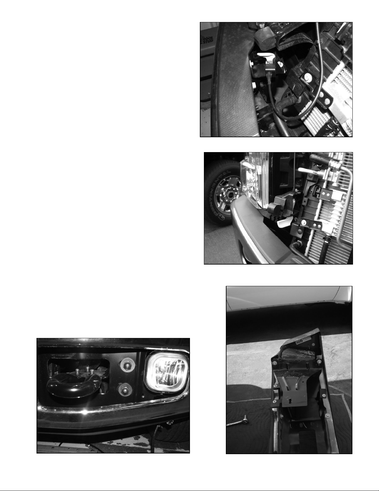
1. Raise vehicle hood and detach hood
latch mechanism from back side of
bumper (Figure 1).
NOTE: On some models, the hood latch
may be located on radiator support and
is not necessary to remove (Figure 1.1).
If equipped with engine heater, and/or
factory fog lamps, detach wiring harness
from back side of bumper.
2. Remove 2 bumper bolts on each side
(Figure 2). Remove rear support brackets
from back side of bumper (Figure 2.1).
Figure 1
Figure 2
Figure 2.1
Figure 1.1
Page 3
- 3 -
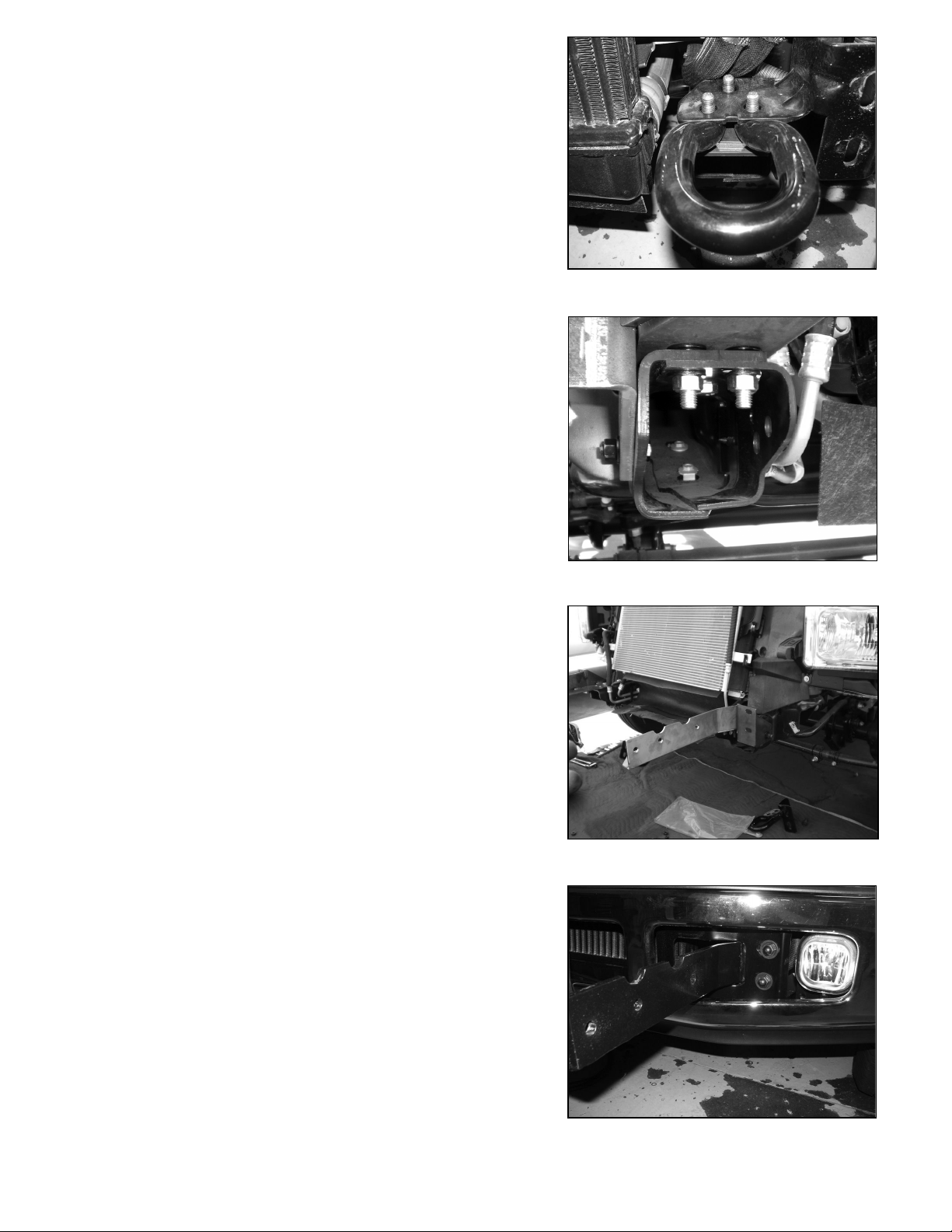
3. Remove tow hooks mounted on end
of frame by removing the 3 bolts
securing tow hook (Figure 3).
4. Install left mounting bracket (Item #4) using (3
per side) 12mm bolts (Item #9) inserted through
the top of the frame rail, lockwashers (item #10),
and nuts (Item #11).
IMPORTANT NOTE: Models F-450 and F-550,
you will need to add (2) washers (Item #13)
(passenger side only) on each of the two front
holes between the mounting bracket and the
frame of the vehicle so to make the guard align
properly. (Figure 4)
Install (2 per side) ½ x 1-½” bolts (Item #12)
inserted through the side of the frame rail, washer
(Item #13) and locknuts (Item #14). (Figure #4.1)
5. Reinstall bumper over mounting
brackets using factory flange nuts.
(Figure 5). Also reinstall rear support
brackets to backside of bumper.
Reinstall hood latch mechanism, engine
heater and fog lamp wiring harness.
NOTE: If installing “RE” style winch, install
winch in mounting channel at this time.
Figure 3
Figure 4.1
Figure 5
Figure 4
Page 4

- 4 -
6. Remove shipping strap and mounting bolts from winch assembly and discard. Place
frame assembly (item #1) over top of winch and secure. Use (3) 3/8-16NC x 1" lg. hx.hd.
capscrews with lockwashers and (1) 3/8-16NC x 3/4 lg. soc.hd. capscrew with high collar
lockwasher (9/16 O.D.) to attach winch to rear angle of frame assembly. DO NOT
TIGHTEN.
Attach winch to front channel of frame assembly, using (3) 3/8-16NC x 1 lg. soc.hd.
capscrews with high collar lockwashers (9/16 O.D.) and (1) 3/8-16NC x 3/4 lg. soc.hd.
capscrew with high collar lockwasher (9/16 O.D.), as shown below. NOTE: The (2)
outer-most capscrews are inserted through holes in face of channel and threaded into
winch. The (2) inner-most holes are placed through channel at fairlead opening and
threaded into winch. Tighten front hardware to proper torque value then tighten
back hardware (see TORQUE VALUE CHART). Snap hole plugs (item #30) into outermost holes in front of frame assembly.
NOTE: The guard side plates have 2
winch channel mounting options
(Figure #8). Repeat for the right side.
Figure 6
Page 5

- 5 -
7. Install guard side plate (Item #2). Using
(2 per side) ½ x 1-½” bolts (Item #12), (4
per side) ½” washers (Item #13) and (2 per
side) ½” locknuts (Item #14), (Figure #7).
Figure 7
Figure 8
8. NOTE: The guard side plates have 2
winch channel mounting options (Figure #8).
Repeat for the right side.
Page 6

- 6 -
11. Install grill tube (Item 6) between guard side
plates using (2) 3/8 x 1¼” bolts (Item 16) and 3/8”
washers (Item 17). (Figure 11). Tighten and align all
hardware at this time (Figure 12).
Figure 10
Figure 11
10. Install winch and mounting channel (Item #1) between
mounting brackets (Item #4 and #5) using (1 per side)
spacer plates (Item #3), (3 per side) ½ x 2” bolts (Item
#15), (6 per side) ½” washers (Item #13) and, (3 per side)
½” locknuts (Item #14). (Figure #10)
9. Install tow hooks (Item #21) (2 per
side) 7/16 x 1-1/2” bolts (Item #22)
and (4 per side) 7/16” washer and (2
per side) 7/16” locknuts on the end of
mounting brackets (Figure 9).
Figure 9
Page 7

- 7 -
13. Place wraparound units and side plates to center unit.
Install right and left wraparound units (items #7 and #8) to
side plates of center unit using (2 per side) 3/8 x 1¼” cap
screws (item #16), (2 per side) 3/8” locknuts (item #18).
Do not tighten until later.
14. Headlight grilles are attached from the
factory to the wraparound units and side plates
of center unit using (2 per side) 3/8 x 1¼”
capscrews (item #16), (4 per side) 3/8” flat
washers (item #17), and (2 per side) 3/8”
locknuts (item #18). Far end of headlight grilles
bolt onto wraparound units. Do not tighten until
later (Figure 13).
15. If needed, install the License Plate Assembly
(item #19) to the underside of the channel (item
#1) using (2) ¼ x 1 capscrews (item #20).
16. Align and tighten all bolts to proper torque
(see chart at right).
Torque Value Chart
Bolt Torque, Torque,
Size ft-lbs. Nm
1/4-20 9.7 13
3/8-16 39 53
7/16 58 78
½-13 87 118
12mm 60 90
17. Install the fairlead using hardware furnished
with the winch. Refer to winch owner’s manual for
complete instructions. Tighten fairlead mounting
bolts to proper torque.
18. Install the winch in the channel according to
mounting instructions in the winch owner’s
manual, using hardware furnished with winch. Do
not tighten mounting bolts until electrical
connections are complete.
19. Refer to winch owner’s manual for electrical
connections. Push battery cables into loom (item
#25) and secure using cable ties (item #24) at
each end of loom. To improve appearance, wrap
end of loom with electrical tape.
IF INSTALLING WRAPAROUND KIT #295956, FOLLOW
STEPS 13-14, OTHERWISE SKIP TO STEP 15.
Page 8

- 8 -
Figure 12
Figure 13
Page 9

- 9 -
295955, 295956 Grill Guard Parts List
ITEM
NO
PART NO.
QTY
DESCRIPTION
1
R-Channel 37
1
Winch Channel Part #395230
2
SP955
2
Guard Side Plate
3
SPACER955
2
Spacer Plate
4
LM955L
1
Lower Left Mount
5
LM955R
1
Lower Right Mount
6
TOPBAR955
1
Grill Tube
7
W955L
1
*Left Wraparound with Grill
8
W955R
1
*Right Wraparound with Grill
9
HCS12mmX50mm
6
Bolt 12mm - 1.75 X 50mm
10
LOCKWASHER ½
6
Lockwashers ½
11
HEXNUT 12mm
6
Hex Nut 12mm
12
HCS ½ X 1.5
8
Bolt 1/2NC-13 X 1-1/2
13
WASHFLAT ½
42
Washer ½
14
LNUT ½ X 13
14
Locknut ½ NC-13
15
HCS ½ X 2
6
Bolt ½ NC-13 X 2
16
HCS 3/8 X 1-1/4
6
**Bolt 3/8 NC-16 X 1-1/4
17
WASHFLAT 3/8
10
**Washer 3/8
18
LNUT 3/8 X 16
4
**Locknut 3/8 NC-16
19
R-408127
1
License Plate Assembly
20
HCS 1/4 -20 x 1
2
Hex Capscrew ¼ x 1”
21
TOW HOOK
2
Tow Hook
22
HCS 7/16-14 x 1-1/2
4
Bolt 7/16NC-14 x 1-1/2”
23
WASHFLAT7/16
8
Washer 7/16
24
LNUT 7/16 X 14
4
Locknut 7/16 NC-14”
25
SCS 3/8 X 1
3
Socket Cap Screw 3/8NC-16 x 1”
26
SCS 3/8 X ¾
2
Socket Cap Screw 3/8NC-16 x ¾”
27
HCS 3/8 X 1
3
Bolt 3/8NC-16 x 1”
28
LOCKWASHER 3/8
3
Lockwasher 3/8 MED.SECT.-BLACK
29
LOCKWASHER 3/8 HICOLLAR
5
Lockwasher 3/8, Hi-Collar
30
PLUG
2
Plug
* Items are included in 295956 WRAPAROUND KIT ONLY.
** Quantity is for 295956 wraparound kit. Quantity is 2 for 295955 Grille Guard Kit.
Page 10

- 10 -
 Loading...