

Page 1

INSTALLATION INSTRUCTIONS
FOR SIERRA GRILLE GUARD KIT #295950
FOR 2008 FORD SUPERDUTY
Notice
Ramsey kits are designed for used with Ramsey Winches only.
Use or sale of kits for other winches or applications voids warranty.
Warning
Ramsey offers mounting kits and winches for various vehicles. In crash tests on a limited number of automotive manufacturers’ vehicles, winches/mounting kits, which have been properly mounted, have not interfered with air bag operation.
The user/customer, or their installer, must verify that the mounting kit does not interfere with the factory air bag sensors,
which must not be relocated or modified in any way.
The user/customer should follow the vehicle manufacturer’s recommendations and those of a qualified mechanic to determine if the winching/mounting kit might interfere with the air bag operation. The user/customer should then determine the
suitability of a winch/mounting kit on a particular vehicle.
PLEASE BE ADVISED THAT THE VEHICLE’S AIR BAG SYSTEM MAY NOT OPERATE PROPERLY IF THE WINCH/
MOUNTING KIT IS NOT MOUNTED IN COMPLIANCE WITH THE VEHICLE MANUFACTURER’S RECOMMENDATIONS.
DO NOT ATTACH TOW HOOKS TO ANY PART OF MOUNTING KIT UNLESS INSTRUCTED TO DO SO.
DO NOT SUBSTITUTE ATTACHING HARDWARE ITEMS (BOLTS, NUTS, OR WASHERS).
READ AND UNDERSTAND WINCH OWNER’S MANUAL BEFORE INSTALLATION AND OPERATION OF THE
WINCH. SEE WARNINGS AND CAUTIONS IN WINCH OWNER’S MANUAL.
IMPORTANT NOTES!
1. RIGHT AND LEFT HAND DIRECTIONS AS IF SEATED BEHIND STEERING WHEEL.
2. ALL FASTENING HARDWARE MUST BE LOOSELY ASSEMBLED UNTIL DIRECTED TO TIGHTEN. TIGHTEN ALL HARDWARE TO PROPER TORQUE AS INSTRUCTED.
RAMSEY WINCH COMPANY
P.O. BOX 581510
TULSA, OKLAHOMA 74158-1510
PHONE: (918) 438-2760 • FAX: (918) 438-6888
Visit us online at www.ramsey.com
913409-0307-A
Page 2
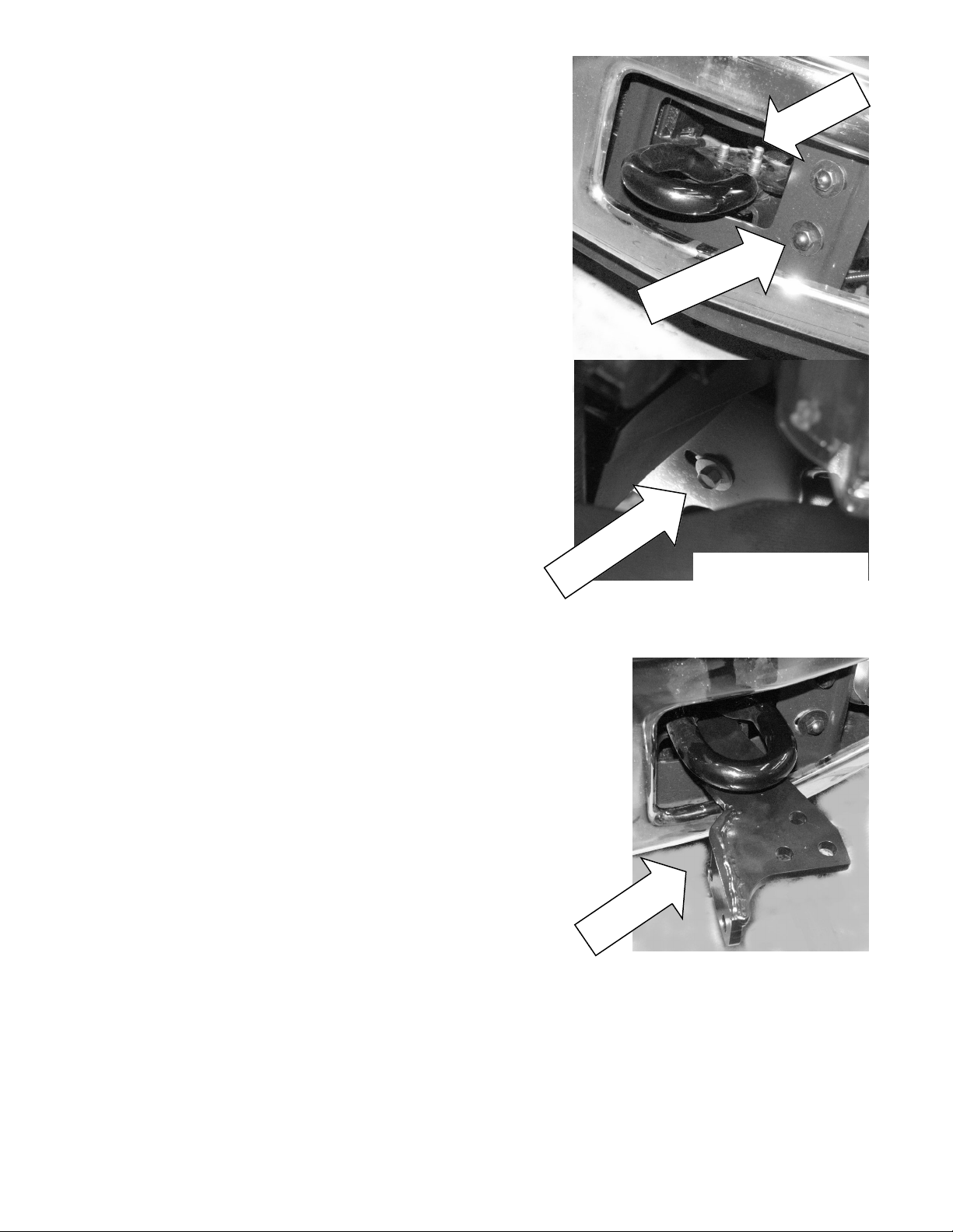
1. Loosen or remove the bumper bracket bolts and lower bumper support
bracket bolts on both sides of vehicle so that the bumper can be moved
sufficiently to allow access to the tow hook bolts.
Remove tow hook bolts from beneath vehicle. Discard bolts.
S
T
L
O
B
K
O
O
H
W
O
T
T
E
K
C
A
R
B
R
E
P
M
U
S
B
T
L
O
B
-
P
U
S
T
L
R
O
E
B
P
T
M
E
U
K
B
C
R
A
E
R
B
W
O
T
L
R
O
P
VIEW LOOKING DOWN
BETWEEN BUMPER AND
RADIATOR.
2. Insert the lower support brackets (item # 3) under the tow hooks. Install
(3 each side) bolts (item # 15) from beneath vehicle through lower support brackets and into tow hooks. Do not tighten.
Replace the bumper bracket bolts and lower support bracket bolts but do
not tighten.
-
T
P
E
U
K
S
C
R
A
E
R
B
W
O
T
L
R
O
P
2
Page 3

3. Assemble channel (item # 2) to center unit (item #1) using (2 each
side) 3/8” bolts and locknuts (items # 10 & 11). Do not tighten.
4. Lift grill guard assembly into place between lower support brackets.
Attach using (2 each side) 1/2” bolts and locknuts (item # 16 & 17).
Do not tighten.
5. Loosen upper bumper support bolt and attach upper support bracket
(item # 5) using existing hardware. Do not tighten.
6. Attach upper support bracket to center unit assembly using (1 each
side) 3/8” bolts and locknuts (items #10 &11). Do not tighten.
3
Page 4

7. Align and tighten hardware on both sides in the following or-
der: (refer to Torque Value Chart at right)
Torque Value Chart
• Tow hook bolts
• Bumper bracket bolts (upper and lower)
• Rear support bracket bolts
• Lower support bracket bolts
• Bolts between channel and grill guard
• Upper support bracket bolts
8. If needed, install the License Plate bracket (item #20) to underside of
Winch Channel using (2) 1/4 bolts, washers, and locknuts (items #7,
8, & 9).
TO INSTALL THE FAIRLEAD AND WINCH, REFER TO THE
WINCH OWNER’S MANUAL.
9. Install the fairlead using hardware furnished with the winch. Note that
the top holes in the channel assembly (item #1)align with the bottom
holes in the roller fairlead.
10. Install the winch in the winch channel using the hardware that comes
with the winch.
11. Refer to the Winch Owner’s Manual for instructions on electrical connections. Be sure cables are not drawn taut across any surfaces
which could possible damage them.
Bolt size Torque, ft-lbs Torque, Nm
1/4-20 5 7
3/8-16 34 46
1/2-13 87 118
12mm 60 90
12. Push battery cables into loom (item #18) and slide loom up cables
as close as possible to mounting frame assembly. Secure using cable ties (item #19) at each end of loom. To improve appearance,
wrap ends of loom with electrical tape.
13. Plug remote switch into receptacle on solenoid. Run winch forward
and reverse to check connections. Snap appropriate “IN” and “OUT”
disk into proper thumb cavity, after determining winch operating direction. Do not leave switch plugged in when not in use.
14. Place end of wire rope through fairlead and attach clevis hook. Use
clevis hook and cotter pin (furnished with winch). Install cable according to instructions in Winch Owner’s Manual.
4
Page 5

2008 Ford Super Duty Grill Guard Kit
5
Page 6

295950 Grill Guard Parts List
ITEM
PART NO. QTY DESCRIPTION
NO.
1
R-CHANNEL321 1 WINCH CHANNEL
2
12950 1 CENTER UNIT
3
LM950L 1 LOWER MOUNT LEFT
4
LM950R 1 LOWER MOUNT RIGHT
5
US950L 1 UPPER SUPPORT LEFT
6
US950R 1 UPPER SUPPORT RIGHT
7
HCS1/4-20X1 2 BOLT 1/4NC-20 X 1 LG BLACK
8
LNUT1/4 2 LOCKNUT 1/4NC-20 BLACK
9
WASHFLAT1/4 2 WASHER 1/4 FLAT BLACK
10
HCS3/8X1 6 BOLT 3/8NC-16 X 1 LG BLACK
11
LNUT3/8-16 6 LOCKNUT 3/8NC-16 BLACK
12
HCS12MMX40mm 6 BOLT 12mm X 1.75 X 40mm LG ZP
13
HEXNUT12mm 6 HEX NUT 12mm ZP
14
LOCKWASHER1/2 6 LOCKWASHER 1/2 ZP
15
HCS12mmX50 6 BOLT 12mm X 1.75 X 50mm BLACK
16
HCS1/2X1.5 4 BOLT 1/2NC-13 X 1-1/2 LG BLACK
17
LNUT1/2-13 4 LOCKNUT 1/2NC-13 BLACK
18
R-LOOM 1 LOOM
19
R-CABLETIE 1 CABLE TIES (PKG)
20
R-408127 1 LICENSE PLATE BRACKET
20
18
19
1
12
13
14
15
16
5
3
17
10
11
7
8
9
6
4
2
6
 Loading...