

Page 1

INSTALLATION INSTRUCTIONS FOR SIERRA
GRILLE GUARD KIT # 295946 AND
WRAPAROUND KIT #295947
ON 1999-2007 FORD F250-550
SUPERDUTY AND 2002-2005 EXCURSION
Notice
Ramsey kits are designed for use with Ramsey Winches only.
Use or sale of kits for other winches or applications voids warranty.
Warning
Ramsey offers mounting kits and winches for various vehicles. In crash tests on a limited number of automotive
manufacturer’s vehicles, winches/mounting kits, which have been properly mounted, have not interfered with air bag
operation.
The user/customer, or their installer, must verify that the mounting kit does not interfere with the factory air bag sensors, which must not be relocated or modified in any way.
The user/customer should follow the vehicle manufacturer’s recommendations and those of a qualified mechanic to
determine if the winching/mounting kit might interfere with the air bag operation. The user/customer should then
determine the suitability of a winch/mounting kit on a particular vehicle.
PLEASE BE ADVISED THAT THE VEHICLE’S AIR BAG SYSTEM MAY NOT OPERATE PROPERLY IF THE
WINCH/MOUNTING KIT IS NOT MOUNTED IN COMPLIANCE WITH THE VEHICLE MANUFACTURER’S RECOMMENDATIONS.
DO NOT ATTACH TOW HOOK TO ANY PART OF MOUNTING KIT UNLESS INSTRUCTED TO DO SO.
DO NOT SUBSTITUTE ATTACHING HARDWARE ITEMS (BOLTS, NUTS, OR WASHERS).
READ AND UNDERSTAND WINCH OWNER’S MANUAL BEFORE INSTALLATION AND OPERATION OF THE WINCH.
SEE WARNINGS AND CAUTIONS IN WINCH OWNER’S MANUAL.
IMPORTANT NOTES!
1. RIGHT AND LEFT HAND DIRECTIONS AS IF SEATED BEHIND STEERING WHEEL.
2. ALL FASTENING HARDWARE MUST BE LOOSELY ASSEMBLED UNTIL DIRECTED TO TIGHTEN.
RAMSEY WINCH COMPANY
P.O. BOX 581510
TULSA, OKLAHOMA 74158
PHONE: (918) 438-2760 • FAX: (918) 438-6888
http://www.ramsey.com
913398-0307-B
Page 2
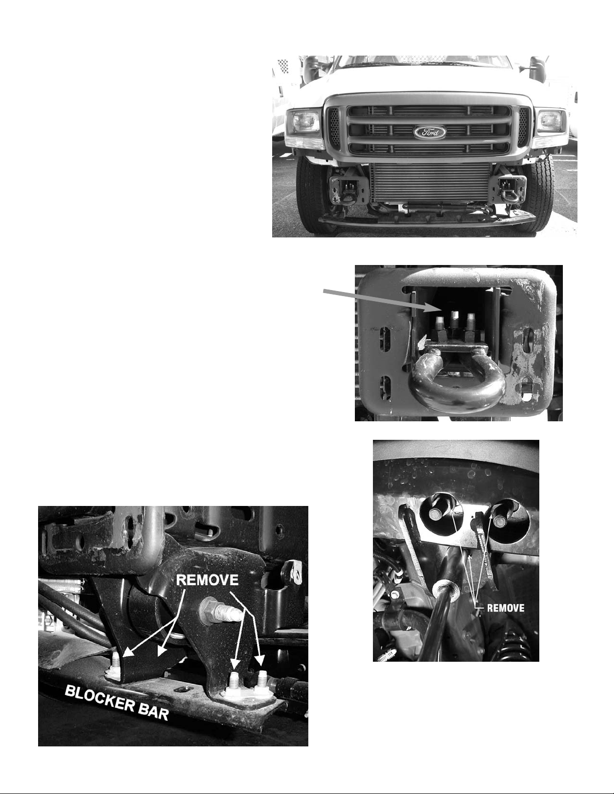
1. Remove vehicle bumper in order to access
tow hooks and frame.
2. Remove tow hooks by removing (3) 12mm factory bolts.
3. Remove the three nuts on the underside of the blocker bar as
shown at lower right. Remove blocker bar.
On some models, to remove the blocker bar, remove the four
bolts that hold the blocker bar to the bracket as shown
below.
2
Page 3
FOR 1999-2004 MODELS:
4. Fasten upper support brackets (item #5 & #6) to vehicle bumper bracket as shown at right using factory hardware.
FOR 2005 MODELS:
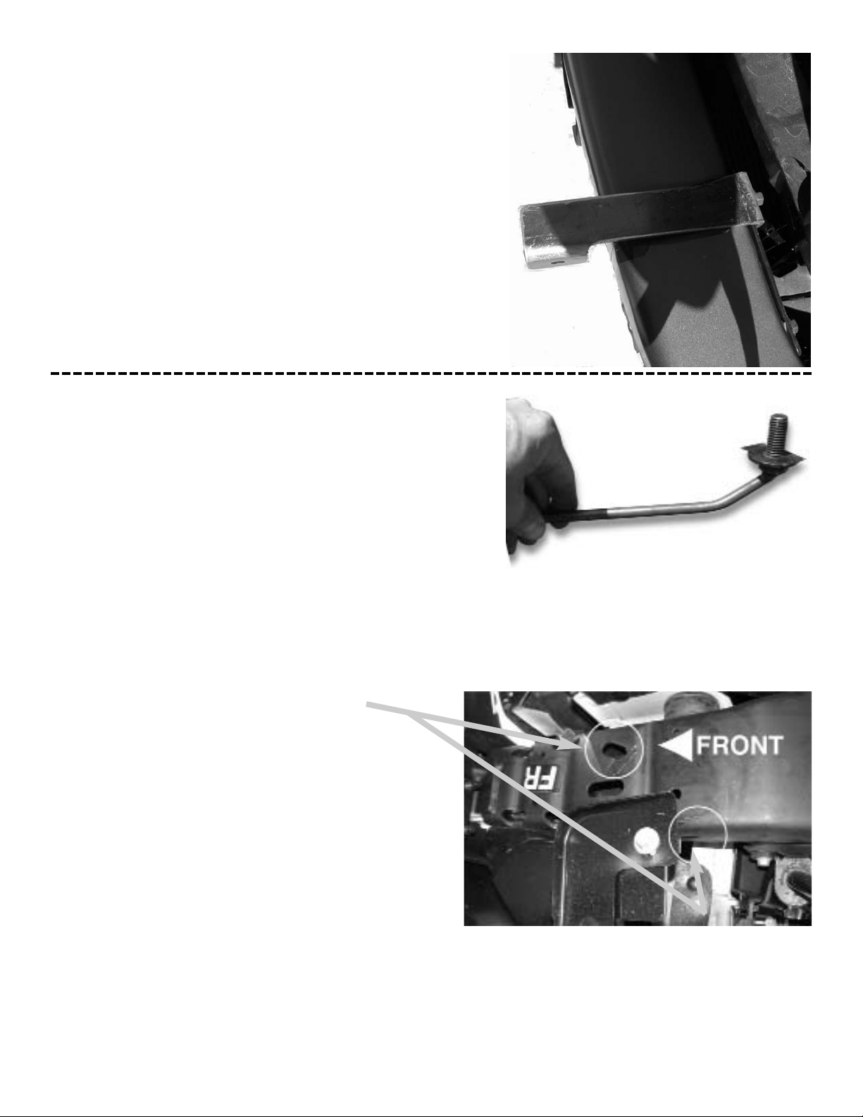
4a. Take (1) 1/2” bolt with rod (item #17) and place (1) 1/2”
flat washer (item #18) on bolt and hold in place using
(1) plastic gasket (item #23), threaded onto bolt.
The following views are looking up from underside of
vehicle with orientation to front of vehicle as indicated.
Driver side shown.
4b. Locate slotted holes in bottom of frame and on outside of
frame rail as shown at right.
3
Page 4

4c. Insert 1/2” bolt with extension through hole in bottom of
frame and position it so that threads extend out of frame
through slotted hole near top of frame.
Use rod extension to maneuver bolt. Bolt threads should
extend out of frame rail as shown at lower right.
4d. With bolt in place, insert upper support bracket (item
#8) on top of frame so that small tab extends out past
vehicle grille and large tab with slotted hole rests over
threads.
4e. Fasten upper support bracket to frame rail using 1/2”
flat washer (item #18) and locknut (item #16). Tighten
until snug.
4f. Repeat for passenger side.
4
Page 5

When properly installed, upper support bracket will protrude from vehicle between the vehicle grille and the top
of the front bumper. Small tab will mount to sideplate of
grille guard.
Note: The outer edges of the upper brackets should
be 32 1/4” or slightly less apart and the inner edges
of the lower brackets should be 32 7/8” or slightly
more apart in order to attach the center unit to them.
Because the mounting hardware for these brackets
need to be tightened prior to attaching the center unit
to them, make sure the spacing is correct before you
tighten the mounting hardware. Once the bumper is
re-installed, it will not be possible to adjust the
mounting hardware for these brackets.
10. Install lower mounting brackets (Item #3 & #4) to
frame rails at tow hook holes. Use (3) 12mm x 40 mm
capscrews (item #11), (3) 1/2” lockwashers (item
#19), and (3) 12mm hex nuts (item #15) per side.
Tighten hardware for upper and lower mounting brackets before bumper is re-installed. Refer to Torque Value
Chart for proper torque.
11. Re-install bumper. Bumper should slip over lower
mounting brackets.
12. Re-install blocker bar.
5
Page 6

13. Install winch channel to center unit using (2) 3/8” x 1 capscrews (item #10), (2) 3/8” locknuts (item #14), and channel gasket (item #20) on each side. Attach loosely.
14. Install center unit to upper brackets using (1) 3/8” X 1 capscrew (item #10), (1) 3/8” locknut (item #14), and upper
mounting bracket gasket (item #22) on each side. Attach
loosely.
15. Install center unit to lower brackets using (2) 1/2” x 1-1/2
capscrews (item #12), (2) 1/2” locknuts (item #16), and
lower mounting bracket gasket (item #21) on each side.
Attach loosely.
6
HOLES FOR
WRAPAROUND
UNIT
HOLES FOR
LITE TUBES
If installing Grille Guard only, skip steps 16-
18.
16. Remove 3/8” capscrew that attaches Center Unit to
Upper Mounting Bracket.
17. Install Wrap Around Right and Left units (Items #27
and #28) to side plates of center unit using (2 per
side) 1/4” capscrews (Item #32) and lock nuts
(Item #33) with wraparound shim (Item #31) and
(2 per hole) washers (Item #34). See previous page
for location of mounting holes. Re-install 3/8” capscrew and locknut through Upper Mounting Bracket,
side plate of Center Section Assembly, and Wrap
Around units.
18. Install Headlight Grille Right and Left units (Item #29
and #30) to Wrap Around units and side plates of
Center unit using (2) 1/4” x 1-1/4” capscrews (Item
#32), and lock nuts (Item #33) with washers (Item
#34). Far end of Headlight Grille units will snap into
Wrap Around units.
Page 7

7
19. Install tow hooks to tapped holes in lower mounting
brackets using (3) 12mm x 50 mm capscrews (item
#13) on each side.
20. If needed, install License Plate Bracket (item #26)
to underside of Winch Channel using (2) 1/4” capscrews (Item # 9).
21. Align and tighten all bolts to proper torque before
installing winch. See Torque Value Chart below.
22. Install the fairlead using hardware furnished with the
winch. Note that the top holes in the Channel
Assembly align with the bottom holes on the roller
fairlead.
23. Install the winch in the Winch Channel according to
mounting instructions in the Winch owner’s manual,
using supplied hardware.
24. Refer to Winch owner’s manual for instructions on
electrical connections. Be sure battery cables are
not drawn taut across any surfaces which could
possibly damage them.
25. Push battery cable into loom (Item #24) and slide
loom up cables as close as possible to mounting
frame assembly. Secure using cable ties (item #25)
at each end of loom. To improve appearance, wrap
ends of loom with electrical tape.
26. Plug remote switch into receptacle on top of solenoid. Run winch forward and reverse to check connections. Snap appropriate “IN” and “OUT” disk into
proper thumb cavity, after determining winch operating direction. Do not leave switch plugged in when
not in use.
27. Place end of wire rope through fairlead and attach
clevis hook. Use clevis pin and cotter pin (furnished
with winch).
Bolt Torque, Torque,
Size ft-lbs. Nm
1/4-20 5 ft-lbs 7 Nm
3/8-16 34 ft-lbs 46 Nm
1/2-13 87 ft-lbs 118 Nm
12mm 60 ft-lbs 90 Nm
Torque Value Chart
Page 8

8
Page 9

9
Parts List
4
22
24
1
2
25
5
6
23
3
19
7
10
8
12
28
14
11
29
21
20
9
30
15
16
17
18
27
13
ITEM
NO.
PART NO. QTY DESCRIPTION
1 R-CHANNEL321 1 WINCH CHANNEL
2 R-P295940 1 CENTER UNIT
3 R-LM940R 1 LOWER MOUNT RIGHT
4 R-0M940L 1 LOWER MOUNT LEFT
5 R-US293R 1 UPPER SUPPORT RIGHT (99-04 MODELS)
6 R-US293L 1 UPPER SUPPORT LEFT (99-04 MODELS)
7 R-US946R 1 UPPER SUPPORT RIGHT (05 MODELS)
8 R-US946L 1 UPPER SUPPORT LEFT (O5 MODELS)
9 HCS1/4-20X1 2 HEX CAPSCREW 1/4NC-20 X 1” LG
10 HCS3/8X1 6 HEX CAPSCREW 3/8NC-16 X 1” LG
11
HCS12mmX40mm
6 HEX CAPSCREW 12mm X 40mm LG
12 HCS1/2X1.5 4 HEX CAPSCREW 1/2NC-13 X 1 1/2” LG
13 HCS12mmX50 6 HEX CAPSCREW 12mm X 50mm COARSE
14 LNUT3/8-16 6 3/8NC-16 LOCKNUT
15 HEXNUT 12mm 6 12mm HEX NUT
16 LNUT1/2-13 6 1/2NC-13 LOCKNUT
17
HCS1/2w/EXTENSION
2 HEX CAPSCREW 1/2 W/EXTENSION ROD
18 WASHERFLAT1/2 4 1/2 FLAT WASHER
19 LOCKWASHER1/2 6 1/2 LOCKWASHER
20 R-GASKETCHAN 2 CHANNEL GASKET (2 HOLES)
21 R-GASKET940LN 2 LOWER BRACKET GASKET (2 HOLES)
22 GASKETUS 2 UPPER BRACKET GASKET (1 HOLE)
23 GASKET1/2 2 GASKET FOR 1/2” BOLT W/EXTENSION ROD
24 R-LOOM 1 LOOM
25 R-CABLETIE 1 CABLE TIE
26 R-408127 1 LICENSE PLATE ASSEMBLY
ADDITIONAL PARTS FOR WRAPAROUND KIT #295947
27 R-W941R 1 WRAPAROUND RIGHT
28 R-W941L 1 WRAPAROUND LEFT
29 R-G293R 1 HEADLIGHT GRILL RIGHT
30 R-G293L 1 HEADLIGHT GRILL LEFT
31 R-GASKET294W 2 WRAP SHIM
32 HCS1/4X1 10 HEX CAPSCREW 1/4NC-20 X 1” LG
33 LNUT1/4 10 1/4NC-20 LOCKNUT
34 WASHFLAT1/4 20 1/4 FLAT WASHERS
31
33
34
26
 Loading...